Search filter
22 results found
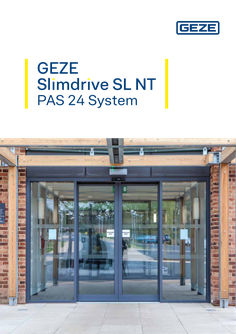
GEZE Slimdrive SL NT PAS 24 System Brochure
GEZE Slimdrive SL NT PAS 24 System … Contents. Introduction to PAS 24 … Slimdrive SL NT - PAS 24 system … Technical drawings … Buildcheck certificate 11 TUV certificate 12 Summary 13 … PAS 24. GREATER DEMANDS ARE BEING PLACED ON BUILDINGS, ESPECIALLY ENTRANCES WHICH NEED TO PROVIDE ACCESSIBILITY, ACCESS CONTROL, EMERGENCY ESCAPE ROUTES AND INCREASINGLY IMPORTANT, SECURITY. PAS 24 is a Product Assessment Specification; it provides a method for testing and assessing the enhanced security performance requirements of doorsets and windows and is intended to resist the methods of attack associated with the casual or opportunist burglar. It is intended to offer a level of security suitable for dwellings and other buildings. • PAS 24 is a UK orientated accreditation and a standard which is recognised throughout the construction industry and by those involved in the security of residential buildings. • Since October 2015 any dwelling must comply with Building Regulation Part Q which states that reasonable provision must be made to resist unauthorised access to any dwelling and any part of a building from which access can be gained to a flat within a building. • PAS 24 is a primary reference in the Building Regulation Approved Document Part Q. Introduced for increasing security in residential dwellings, its key points are now being cascaded to other types of buildings where security with escape routes are a high priority such as hospitals, or buildings where security is the highest consideration such as airports, train stations and banks. … PAS 24 TESTING Under PAS 24 a series of tests are performed including manual attack, in which the test engineer uses a range of tools anywhere on the door over a 15 minute period, impact testing of both ‘soft body’ and ‘hard body’ objects, and force testing in which loads are applied for up to … minutes. The door must withstand all of the tests. GEZE UK have worked with Jack Aluminium Systems, one of the UK’s leading aluminium glazing systems companies, to develop this new security system for automatic sliding doors. GEZE is at the forefront in the UK in achieving and meeting the requirements for this enhanced security standard with its new PAS 24 automatic sliding door system. … 6 Benefits of the Slimdrive SL NT with PAS 24 accreditation . VISUAL The locking system is hidden from view, making it more difficult for the opportunist burglar to attack and contributing to an aesthetically pleasing entrance. SECURITY The Slimdrive SL NT with PAS 24 accreditation is not just a lock but a whole door system with a specially designed, unique locking system that uses existing tried and tested technology integrated with GEZE systems. It will protect against opportunistic burglary or attack. ESCAPE Securing those inside a building is not the only priority, in an emergency fast evacuation from a building is imperative. The system functionality allows the door state to be set to fail safe, i.e. open and remain open on alarm activation, if this is a requirement of the building escape strategy, guaranteeing that the door will not become an obstacle when exiting the building. ACCESS CONTROL Maintaining security yet still allowing 24 hour access control is easy for the Slimdrive SL NT with PAS 24, the system has been designed and tested to be used continuously with access control. A significant advantage of the GEZE system is that the door is locked upon each activation providing the assurance of PAS 24 security every time it locks. This functionality can even be maintained in the event of a complete power failure for a period of time if required. … Slimdrive SL NT. GEZE’s Slimdrive SL NT with PAS 24 accreditation has all the advantages of the latest Slimdrive technology. At just seven centimetres the automatic operator is the slimmest on the market enabling the Slimdrive SL NT to be almost invisibly integrated into the façade -perfect for glass façades. It can also move leaf weights up to 125kg and is virtually silent in operation and now with PAS 24 accreditation the highest level of security is assured. … Features of the GEZE Slimdrive SL NT at a glance • • • • • • Simple to install and maintain Can be installed on to a single transom GEZEconnects - the wireless interface Increased leaf weights: … x 125kg Self-cleaning roller carriage Safety tested to DIN 18650 Dimensions - Unique and only from GEZE: The 7cm high drive • Drive installation dimensions: 70mm x 190mm (height x depth) • Drive type: single and double leaf variants possible • Weight: up to 125kg per leaf • Opening width: Single leaf only 900mm to 1500mm Double leaf 900mm to 3000mm … Single . 190 42 31 15 70 … DOOR TOP RAIL … 22 105 TRAVEL … 22 OPENING HEIGHT CLEARANCE TO CONFORM TO EN16005 TO DO THIS A POCKET SCREEN MAY BE REQUIRED 42 31 15 70 MAX 1500mm / MIN 900mm DOOR TOP RAIL 190 OPENING HEIGHT 22 22 DOOR BTM RAIL DOOR BTM RAIL … 50 DOOR = OW/2+105 10 10 OPERATOR LENGTH 190 15 PACKAGE WIDTH 3000mm MAX MAX 1500mm / MIN 900mm 50 42 31 70 DOOR TOP RAIL … 22 OPENING HEIGHT OPE HE 22 CLEARANCE TO CONFORM TO EN16005 TO DO THIS A POCKET SCREEN MAY BE REQUIRED 105 TRAVEL DOOR BTM RAIL … DOOR = OW/2+105 50 10 10 Bi-parting . CLEARANCE TO CONFORM TO EN16005 TO DO THIS A POCKET SCREEN MAY BE REQUIRED TRAVEL DOOR = OW/2+105 105 … 10,5 CLEARANCE TO CONFORM TO EN16005 … 10,5 MAX 3000mm / MIN 900mm CLEARANCE TO CONFORM TO EN16005 TO DO THIS A POCKET SCREEN MAY BE REQUIRED TRAVEL 105 DOOR = OW/2+105 … 10,5 … 10,5 MAX 3000mm / MIN 900mm OPERATOR LENGTH PACKAGE WIDTH 6000mm MAX CLEARANCE TO CONFORM TO EN16005 11 12 13 A Perfect Entrance System . THE GEZE SLIMDRIVE SL NT PAS 24 SYSTEM ACHIEVES OUTSTANDING SECURITY, WHILST MEETING THE EVER GREATER DEMANDS ON BUILDINGS. The system combines increased security the whole door system utilises a secure locking system using tried and tested technology with a fully failsafe electronic locking system for fast evacuation in an emergency. Maintaining security yet still allowing 24 hour access control is also easy with the Slimdrive SL NT with PAS 24 - it’s been designed and tested to be used continuously with access control. As the robust locking system on the Slimdrive SL NT with PAS 24 is hidden from view it is harder for an opportunist burglar to identify the easiest point to attack and provides a more aesthetically attractive entrance. GEZE’s proven technology of the Slimdrive SL NT together with the fully tested PAS 24 security system all adds up to the perfect entrance system offering accessibility, access control, emergency escape routes and security. 14 UK Headquarters GEZE UK Ltd. Blenheim Way, Fradley Park, Lichfield, Staffordshire WS13 8SY Tel: +44 (0) 1543 443000 Fax: +44 (0) 1543 443001 Email: info.uk@geze.com Web: www.geze.co.uk Connecting expertise building solutions.
PDF | 3 MB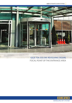
TSA 355/395
GEZE AUTOMATIC DOOR SYSTEMS GEZE TSA 355/395 REVOLVING DOORS FOCAL POINT OF THE ENTRANCE AREA B E W E G UN G M I T S YS T EM Revolving door systems GEZE TSA 355 CONTENTS Introduction … GEZE TSA 355 revolving door drive … GEZE TSA 395 revolving door drive 16 GEZE TSA 395 Multi revolving door drive 21 Certificates 26 References 28 Revolving door systems … Revolving door systems GEZE TSA 355 GEZE revolving door systems Focal point of the entrance area The entrance area is the face of the building and thus of the enterprise. Therefore it is imperative to validate the positive visual impression through the faultless function of the door system even in the case of high access frequency. GEZE revolving doors meet these requirements and enthral planners, but also owners and users of buildings alike. The virtually unlimited design freedom and the complete selection of materials and colours meet the highest architectural requirements. Revolving doors also offer good protection against draught as they are open and closed at the same time. By eliminating draught in the entrance area, the immediate environment can be used commercially with noise, dust and dirt being kept out. The clear spatial separation between the interior and exterior as well as the energy savings offer significant cost advantages and make the use of revolving doors even more advantageous. The scope of use of revolving doors is manifold. They are suitable for: • Commercial buildings • Public buildings • Shopping centres • Hotels and restaurants • Administrative buildings • Car dealerships • Airports and railway stations GEZE revolving doors are customised for each individual project. Various different options and versions are available. Please contact us if the variant you want differs from the dimensions and options mentioned. We offer a door for every entrance. Tüyap Palace, Istanbul … GEZE AUTOMATIC DOOR SYSTEMS Revolving door systems GEZE TSA 355 Advantages for all target groups Advantages for planners and builders: • Design freedom and project specific customised planning with a range of options • Commercial use of the entrance area for shops, offices, showrooms and a reception desk • Harmonious visual appearance of the façade and interior • Prestigious entrance with excellent visual effect • Improvement of the building’s energy balance • Economical solution thanks to the high level of factory prefabrication Advantages for users: • Flawless and smooth operation of the door system even in the case of high access frequency. • Easy setting of desired mode of operation • Effective protection against noise, dust and dirt • Protection against draught Advantages for processors: • Flexible modular system • Easy installation thanks to the high level of factory prefabrication • Predefined and programmed control technology for quick commissioning • The door system and safety devices comply with the currently applicable standards and regulations Latanya Otel, Ankara Revolving door systems … Revolving door systems GEZE TSA 355 GEZE TSA 355 revolving door drive The versatile door drive The TSA 355 model has a very wide range of applications and can be used universally. With a diameter ranging from 1800 mm to 4000 mm and a manual version or a fully automatic drive, exactly the right variant is always available. The doors can be made individually in any desired diameter and passage height. A versatile selection is also available in the surface and colour design. The door is available in 3- or 4-leaf versions and offers an additional night-time closer. The door system has been tested and certified according to EN 16005. Thanks to the variant with optionally available folding leaves (break-out), revolving doors are also suitable for use in escape and rescue routes, depending on building regulations and the required width of the escape route. The TSA 355 door system is the optimal solution in buildings with low as well as high public access frequency. Hotel Hilton Garden Inn, Ankara … GEZE AUTOMATIC DOOR SYSTEMS Revolving door systems GEZE TSA 355 Technical data Standard features System Emergency stop switch Push pad Manual operation Radar movement detector Front post safety sensor Post safety Curved glasses Glass for leaves Locking Roof Brushes Ceiling Glass seal Canopy Colour Illumination Control panel Optional features Stainless steel cladding Gold coloured stainless steel cladding Entrance mat Door handle Coloured glass Passage height in various dimensions Canopy height in different dimensions Night-time closer Break-out leaves Manual locking + switch Waterproof roof for the exterior, with drain channel … pcs. downlights extra 20x30x2 mm stainless steel floor ring Hot-air curtain Control panel with touchscreen automatic one for each entrance and exit one for each entrance and exit possible as an option one for each entrance and exit one for each entrance and exit standard for each entrance … mm LSG … mm LSG manual locking/automatic locking waterproof roof with waterspout 40 mm horse hair brushes 12 segments made of … mm thick aluminium sheet EPDM aluminium profile, canopy height 200 mm/300 mm possible (depending on diameter) natural anodised or RAL colours … x 10 W LED downlight control panel with position switch ● ● ● ● ● ● ● ● ● ● ● ● ● ● ● Revolving door systems … Revolving door systems GEZE TSA 355 Technical data Standard • Error detection combined with flashing LEDs • On/off switch for lighting • Programme switch for change between modes of operation Automatic, Manual and Night Post safety Front post safety sensor Access for people with disabilities and for the elderly Light curtain Push pad Emergency stop switch … Optional touch panel • On/off switch for lighting • Modes for testing and error detection • Setting speed control and waiting periods • Setting for limiting the torque • Settings for stop and start periods • All revolving door settings can be made using this touch screen GEZE AUTOMATIC DOOR SYSTEMS Heel protection Revolving door systems GEZE TSA 355 Technical data (4-leaf) KH = 300 mm FRONTAL VIEW .51 80 48 … GEZE .75 68 GEZE GEZE 35 … sh bru air m eh 5m s r Ho e - … Siz … 30 66 DETAIL A GEN S T OP Ø15 … 4 Ø50 EM DH = 2200 mm ER CY GH = 2500 mm … am L +4 ted ina STOP k GH = Total height DH = Passage height KH = Canopy height … 80 … 4+ ed at in m La 80 … = Manual locking … 2 = Control panel/programme switch … = Emergency stop switch … = Push pad … = Brush sealing … = Heel protection DETAIL B PLAN VIEW 13 r eB urs m Ho ck … m Bla e - … Siz … 10 … us … h … 3 A … 12 … B DETAIL C … 4 50 C … INTERIOR … 55 10 … 75 11 ÖW = 1994 mm 150 DETAIL D Ø 3000 mm … = Radar movement detector … = Glass sealing … = Central shaft … = … mm LSG … = 80x30 mm aluminium profile … = Heel protection … = Emergency stop switch … = Push pad … = Control panel/programme switch 10 = Post safety 11 = Post attachment profile 12 = 10 W LED 13 = Front post safety sensor ÖW = Opening width Revolving door systems … Revolving door systems GEZE TSA 355 Technical data (3-leaf) KH = 300 mm FRONTAL VIEW 66 30 … GEZE ted ina am 4L 4+ GEZE 80 … 35 48 .75 .51 68 DH = 2200 mm … EM DETAIL A ER GEN CY GH = 2500 mm STOP S T OP 80 50 Ø1 … 80 k … = Manual locking … = Control panel/programme switch … 3 = Emergency stop switch … = Push pad GH = Total height DH = Passage height KH = Canopy height … PLAN VIEW 4+4 Laminated Ø50 DETAIL B … 13 … 6 … 35 80 … 3 12 Black Hourse Brush Size - 45 mm 11 DETAIL C … j i … 50 11 55 75 h … 10 … ÖW= 1368 mm Ø 3000 mm … = Radar movement detector … = Glass sealing … = Central shaft … = 80x30 mm aluminium profile … = Heel protection … = Emergency stop switch … = Push pad 10 GEZE AUTOMATIC DOOR SYSTEMS … = Control panel … = Post safety 10 = Post attachment profile 11 = 10 mm LSG 12 = 10 W LED 13 = Front post safety sensor ÖW = Opening width … 7 150 DETAIL D Revolving door systems GEZE TSA 355 KH = 300 mm Technical information automatic revolving door without central shaft .51 68 GEZE GEZE 48 GEZE .75 … 35 80 … STOP h rus ir b ha mm rse 45 o H e Siz ina am ted 30 66 EM GEN CY DH = 2200 mm GH = 2500 mm … ER 4L 4+ ST OP DETAIL A … Ø150 k … 5 GH = total height DH = Passage height KH = Canopy height DETAIL B r eB urs m Ho ck … m Bla e - … Siz … = Manual locking … = Control panel/programme switch … = Emergency stop switch … = Push pad … = Brush sealing … = Heel protection PLAN VIEW h us 10 13 … 2 … 8 … A … 12 DETAIL C … 16 B … 6 … 11 10 … 55 75 C 150 … DETAIL D ÖW = 1994 mm Ø 3000 mm … = Radar movement detector … = Glass sealing … = Central shaft … = … mm LSG … = 80x30 mm aluminium profile … = Heel protection … = Emergency stop switch … = Push pad … = Control panel 10 = Post safety 11 = Post attachment profile 12 = 10 W LED 13 = Front post safety sensor ÖW = Opening width Revolving door systems 11 Revolving door systems GEZE TSA 355 Dimensions 3-leaf revolving doors Outer Inner diameter diameter Leaf width Passage width Segment Maximum Capacity/ Maximum Capacity/ Maximum Capacity/ area number of minute ** number of minute ** number of minute ** in m² people * people * people * … 8 … 8 … 15 … 23 … 15 … 6 … 30 … 38 … 23 … 44 … 30 1800 1740 840 760 2000 1940 940 860 2200 2140 1040 960 2400 2340 1140 1060 2600 2540 1240 1160 2800 2740 1340 1260 3000 2940 1440 1360 3200 3140 1540 1460 3400 3340 1640 1560 3600 3540 1740 1660 3800 3740 1840 1760 All dimensions in mm * Specifies the number of people who can be in one segment during typical use. ** Specifies the maximum number of people that can pass in one direction per minute. 4-leaf revolving doors Outer Inner diameter diameter 1800 1740 2000 1940 2200 2140 2400 2340 2600 2540 2800 2740 3000 2940 3200 3140 3400 3340 3600 3540 3800 3740 All dimensions in mm Leaf width Passage width 840 940 1040 1140 1240 1340 1440 1540 1640 1740 1840 1140 1360 1500 1640 1780 1920 2060 2200 2340 2480 2620 Segment Maximum Capacity/ Maximum Capacity/ Maximum Capacity/ area number of minute ** number of minute ** number of minute ** in m² people * people * people * … 10 … 20 … 30 … 10 … 10 … 40 … 20 … 50 … 30 * Specifies the number of people who can be in one segment during typical use. ** Specifies the maximum number of people that can pass in one direction per minute. Different dimensions and equipment options available on request 12 GEZE AUTOMATIC DOOR SYSTEMS Revolving door systems GEZE TSA 355 Night-time closer 3-leaf 4-leaf Revolving door systems 13 Revolving door systems GEZE TSA 355 Variant with folding leaves (break-out) 3-leaf 4-leaf 14 GEZE AUTOMATIC DOOR SYSTEMS Revolving door systems GEZE TSA 355 Hot-air curtains 3-leaf GEZE GEZE STOP EM GEN CY ER ST OP 4-leaf GEZE GEZE GEZE STOP EM GEN CY ER ST OP Differences between the temperature inside a building and the outside temperature cause unwanted air exchange in the door area. Air curtain systems are used to prevent this air exchange. They prevent the penetration of cold air even with revolving doors. As a result, the area directly by the door can be used economically. Revolving door systems 15 Revolving door systems GEZE TSA 395 GEZE TSA 395 revolving door drive The drive for large doors The TSA 395 model is the optimal choice for buildings with central access with high access frequency. The large door segments facilitate comfortable access to the building. This allows high visitor flows to be handled safely and representative façade entrances to be created. TSA 395 is available as a 3- or 4-leaf version up to a diameter of 6000 mm. A versatile selection is also available in the surface and colour design. A night-time closer can be selected as an additional option. Only an automatic variant is available due to the size of the door system. The central area of the door systems can optionally be equipped with a showcase for further individual design, for example for advertising purposes. The door system has been tested and certified according to EN 16005. Thanks to the optionally available folding leaves (break-out), revolving doors are also suitable for use in escape and rescue routes, depending on building regulations and the required width of the escape route. This door variant is the optimal choice for projects with the following requirements: • High person capacity • High access convenience • High degree of customisation in diameter, height, features and options • Version with … or … leaves, with and without showcase This model is particularly suitable for shopping centres, furniture stores or airports. Galeri Resort, Antalya 16 GEZE AUTOMATIC DOOR SYSTEMS Revolving door systems GEZE TSA 395 Technical data Standard features System Emergency stop switch Push pad Post safety Manual stop possible Passive seal to prevent hands from becoming trapped Radar movement detector Heel protection Presence detector Curved glasses Glass for leaves Locking Roof Brushes Ceiling Glass seal Canopy Colour Illumination Control panel Optional features Stainless steel cladding Gold coloured stainless steel cladding Bright stainless steel panel Entrance mat Door handle Coloured glass Heel protection for safety (below) Passage height in various dimensions Extra manual locking Break-out leaves Extra manual locking and switch Waterproof roof for the exterior, with drain channel … LED lights 10 W extra 20x30x2 mm stainless steel floor ring Hot-air curtain automatic one for each entrance and exit one for each entrance and exit standard for each entrance standard for each entrance one for each entrance and exit at the bottom of the leaves one for each entrance and exit … mm LSG … mm LSG manual locking MDF cover for the interior aluminium sheet for the exterior area 40 mm horse hair brushes 12 segments made of … mm thick aluminium sheet EPDM aluminium and steel profiles natural anodised or RAL colours … x … W LED downlight control panel with position switch ● ● ● ● ● ● ● ● ● ● ● ● ● ● ● Revolving door systems 17 Revolving door systems GEZE TSA 395 Technical data Standard • On/off switch for lighting • Modes for testing and error detection • Setting speed control and waiting periods • Setting for limiting the torque • Setting for start and stop periods • All revolving door settings can be made using this touch screen Standard Post safety Front post safety sensor Access for people with disabilities and for the elderly Mobile safeguarding device Push pad Heel protection Emergency stop switch 18 GEZE AUTOMATIC DOOR SYSTEMS Revolving door systems GEZE TSA 395 Technical data FRONTAL VIEW 30 … AD KH 80 edoa r ® edoa r ® edoa r ® 35 .75 48 … STOP 68 edoa r ® .51 DH GH … EM GEN C ER ST OP DETAIL A … 4+4 mm Laminate 30 … 1 = Manual locking … = Control panel/programme switch … = Emergency stop switch … = Push pad … = Brush sealing … 12 14 DETAIL B PLAN VIEW … 6 … 35 80 13 AD = Outer diameter GH = Total height DH = Passage height KH = Canopy height … EXTERIOR iGoGoGiGTG[\G 11 DETAIL C … B 10 11 C … 10 INTERIOR h … 9 ÖW … = Radar movement detector … = Glass sealing … = Integrated showcase … = 80x30 mm aluminium profile … = Emergency stop switch … = Push pad … = Control panel … 8 = Post safety … = Attachment profile post 10 = … mm LSG 11 = … mm LSG 12 = 10 Watt LED 13 = Front post safety sensor 14 = Radar movement detector ÖW = Opening width … 6 DETAIL D … = Manual locking Revolving door systems 19 Revolving door systems GEZE TSA 395 Dimensions 3-leaf revolving doors Outer Inner diameter diameter 3-leaf with triangular showcase 4000 3940 4500 4440 5000 4940 6000 5940 3-leaf without showcase 4000 3940 4500 4440 5000 4940 All dimensions in mm Leaf width Passage width Segment area in m² Maximum number of people * Capacity/ minute ** Maximum number of people * Capacity/ minute ** 1270 1520 1770 2270 1800 2050 2300 2820 … 8 10 15 53 60 75 112 … 2 … 4 15 15 22 30 1740 1990 2240 1800 2050 2300 … 10 14 68 75 105 … 2 … 15 15 22 * Specifies the number of people who can be in one segment during typical use. ** Specifies the maximum number of people that can pass in one direction per minute. 4-leaf revolving doors Outer Inner diameter diameter 4-leaf with square showcase 4000 3940 4500 4440 5000 4940 6000 5940 4-leaf without showcase 4000 3940 4500 4440 5000 4940 All dimensions in mm Leaf width Passage width Segment area in m² Maximum number of people * Capacity/ minute ** Maximum number of people * Capacity/ minute ** 1320 1570 1850 2320 2700 3000 3400 4170 … 8 11 14 60 82 110 140 … 2 … 3 10 20 20 30 1740 1990 2240 2700 3000 3400 … 9 11 70 90 110 … 2 … 10 20 20 * Specifies the number of people who can be in one segment during typical use. ** Specifies the maximum number of people that can pass in one direction per minute. Different dimensions and equipment options available are available on request 20 GEZE AUTOMATIC DOOR SYSTEMS Revolving door systems GEZE TSA 395 MULTI GEZE TSA 395 Multi revolving door drive The universal door drive The TSA 395 Multi model is the optimal choice for buildings with central access with high access frequency. Due to the 2-leaf design in the door area, there are particularly large segments which allow for comfortable building access. As a result, this door variant can also be used with luggage or shopping trolleys as well as by wheelchair users with an accompanying person. As a revolving door with an integrated linear sliding door, this door system is very flexible. The sliding door function also allows for the comfortable transport of longer objects or the passage of larger groups of people in the shortest time possible. The model is available up to a diameter of 5400 mm and creates representative entrances. A versatile selection is also available in the surface and colour design. The laterally integrated showcases can optimally be used for advertising purposes. At night, the showcases are placed in front of the entrance. This door variant is optimal in projects with the following requirements: • High person capacity • High access convenience • Version with … door leaves and integrated sliding door This model is therefore ideal for use in shopping centres, furniture stores and airports. Forum Kayseri Revolving door systems 21 Revolving door systems GEZE TSA 395 MULTI Technical data Standard features System Emergency stop switch Push pad Post safety Passive seal to prevent hands from becoming trapped Radar movement detector Heel protection Presence detector Curved glasses Glass for leaves Roof Brushes Soffit Glass seal Canopy Colour Illumination Control panel Optional features Stainless steel cladding Gold coloured stainless steel cladding Bright stainless steel panel Entrance mat Door handle Coloured glass Heel protection for safety (below) Passage height in various dimensions Engine block heater Waterproof roof for the exterior, with drain channel … LED lights 10 W extra 20x30x2 mm stainless steel floor ring Hot-air curtains 22 GEZE AUTOMATIC DOOR SYSTEMS automatic one for each entrance and exit one for each entrance and exit standard for each entrance standard for each entrance one for each entrance and exit at the bottom of the leaves one for each entrance and exit … mm LSG … mm LSG MDF cover for the interior aluminium sheet for the exterior area 70 mm horse hair brushes 12 segments made of … mm thick aluminium sheet EPDM aluminium and steel profiles natural anodised or RAL colours … x 10 W LED downlight control panel with position switch ● ● ● ● ● ● ● ● ● ● ● ● ● Revolving door systems GEZE TSA 395 MULTI Technical data Standard • On/off switch for lighting • Modes for testing and error detection • Setting speed control and waiting periods • Setting for limiting the torque • Setting for start and stop periods • All revolving door settings can be made using this touch screen Standard Post safety Presence detector Access for people with disabilities and for the elderly Heel protection Push pad Emergency stop switch Mobile safeguarding devices Revolving door systems 23 Revolving door systems GEZE TSA 395 MULTI Technical data FRONTAL VIEW GEZE GEZE KH GEZE … D STOP GEZE GE ER N CY EM DH … GH 12 … S T OP 80 … ID … = Control panel … = Emergency stop switch … = Push pad … = Brush sealing 35 80 OD ID = Inner diameter AD = Outer diameter GH = Total height DH = Passage height KH = Canopy height DETAIL B PLAN VIEW EXTERIOR … 6 … 7 … 2 10 … DETAIL C … C B D 1935 … 13 12 15 11 … INTERIOR 24 GEZE AUTOMATIC DOOR SYSTEMS 30 … 6 2030 4200 … = Radar movement detector … = Glass sealing … = Presence detector … = 80x30 mm aluminium profile … = Emergency stop switch … = Push pad … = Control panel … = Hand sensor … 8 … 10 A … = Post safety 10 = … mm + … mm LSG 11 = Sensor cover 12 = 10 W LED 13 = Light curtain sensor 14 = Radar movement detector 15 = Sliding door ÖW = Opening width DETAIL D 30 DETAIL A Revolving door systems GEZE TSA 395 MULTI Dimensions Outer diameter Inner diameter 3600 3540 4200 4140 4500 4440 4800 4740 5400 5340 All dimensions in mm Door system installation width 3840 4440 4740 5040 5640 Passage width revolving door 1530 1780 1980 2030 2290 Passage width sliding door Maximum number of persons * Capacity/ minute ** Maximum number of persons * Capacity/ minute ** 1650 1930 2040 2200 2480 … 7 … 9 11 75 95 100 105 115 … 2 … 3 … 8 … 10 12 12 * Specifies the number of people who can be in one leaf during typical use. ** Specifies the maximum number of people that can pass in one direction per minute. Position night/locked B Automatic operation revolving door Position sliding door operation Revolving door systems 25 Revolving door systems GEZE AUTOMATIC REVOLVING DOOR SYSTEMS 26 GEZE AUTOMATIC DOOR SYSTEMS Revolving door systems GEZE AUTOMATIC REVOLVING DOOR SYSTEMS Revolving door systems 27 Revolving door systems GEZE AUTOMATIC REVOLVING DOOR SYSTEMS References University of Manchester, Great Britain Conforium Hotel, Istanbul, Turkey 28 GEZE AUTOMATIC DOOR SYSTEMS Revolving door systems GEZE AUTOMATIC REVOLVING DOOR SYSTEMS Shopping centre, Özdemir Park, Zonguldak, Turkey Ankara Ticaret Merkezi office building, Ankara, Turkey Revolving door systems 29 Innovative system solutions POTENTIAL APPLICATIONS OF GEZE PRODUCTS Door technology 01 Overhead door closers 02 Hold-open systems 03 Integrated door closers 04 Floor springs and all-glass fittings 05 Sliding fitting systems and linear guides 13 04 Automatic door systems 06 11 Swing doors 01 07 Sliding, telescopic and folding doors 08 Curved sliding doors 09 Revolving doors 10 Activation devices and sensors 02 22 06 17 06 11 04 Smoke and heat extraction and window technology 11 Fanlight opening systems 12 Electric opening and locking systems 13 Electrical spindle and linear drives 14 Electric chain drives 08 20 14 15 Smoke and heat extraction systems Safety technology 16 Emergency exit systems 17 Access control systems 18 Panic locks 19 Electric strikes 20 Building management system Glass systems 21 Manual sliding wall systems (MSW) 22 Integrated all-glass systems (IGG) 30 GEZE AUTOMATIC DOOR SYSTEMS 07 10 07 Innovative system solutions POTENTIAL APPLICATIONS OF GEZE PRODUCTS Door technology The functionality, superior performance and reliability of GEZE door closers are impressive. A common design across the range, the ability to use them on all common door leaf widths and weights, and the fact that they can be individually adjusted makes their selection simple. They are continually being improved and enhanced with up-to-date features. For example, the requirements of fire protection and accessibility are fulfilled with a door closer system. Automatic door systems 15 GEZE automatic door systems open up a huge variety of options in door design. The latest, innovative high-performance drive technology, safety, ease of accessibility and first class universal drive design set them apart. GEZE offers complete solutions for individual requirements. 17 Smoke and heat extraction and window technology 21 GEZE smoke and heat extraction systems and ventilation technology provide complete systems solutions combining the many requirements of different types of windows. We supply a full range from energy efficient drive systems to natural ventilation and complete solutions for supplying and extracting air, also as certified SHEVs. 15 05 12 03 Safety technology GEZE safety technology sets the standards where preventative fire protection, access control and anti-theft security in emergency exits are concerned. For each of these objectives GEZE offers tailored solutions, which combine the individual safety requirements in one intelligent system and close doors and windows in case of danger in a coordinated manner. 21 18 Building systems 16 09 19 In GEZE’s Building Management System GEZE door, window and safety products can be integrated in to the security and control systems of the building. A central control and visualisation system monitors various automation components in the building and offers security through many different networking capabilities. Glass systems GEZE glass systems stand for open and transparent interior design. They can either blend discreetly into the architecture of the building or stand out as an accentuated feature. GEZE offers a wide variety of technologies for functional, reliable and aesthetic sliding wall or sliding door systems providing security with lots of design scope. Revolving door systems 31 GEZE AUTOMATIC DOOR SYSTEMS GEZE GmbH P.O. Box 1363 71226 Leonberg Germany GEZE GmbH Reinhold-Vöster-Straße 21-29 71229 Leonberg Germany Tel. +49 7152 203 … Fax +49 7152 203 310 www.geze.com Germany GEZE GmbH Niederlassung Süd-West Breitwiesenstraße … 71229 Leonberg Tel. +49 7152 203 594 Fax +49 7152 203 438 leonberg.de@geze.com GEZE GmbH Niederlassung Süd-Ost Parkring 17 85748 Garching bei München Tel. +49 7152 203 6440 Fax +49 7152 203 77050 muenchen.de@geze.com GEZE Service GmbH Niederlassung Süd Parkring 17 85748 Garching bei München Tel. +49 1802 923392 Fax +49 7152 9233 859 service-muenchen.de@geze.com GEZE Service GmbH Niederlassung Mitte/Luxemburg Siemensstraße 14 63263 Neu-Isenburg Tel. +49 1802 923392 Fax +49 7152 9233 659 service-frankfurt.de@geze.com GEZE Service GmbH Niederlassung West Heltorfer Straße 12 40472 Düsseldorf Tel. +49 1802 923392 Fax +49 7152 9233 559 service-duesseldorf.de@geze.com GEZE Service GmbH Niederlassung Ost Albert-Einstein-Ring … 14532 Kleinmachnow bei Berlin Tel. +49 1802 923392 Fax +49 7152 9233 759 service-berlin.de@geze.com China GEZE Industries (Tianjin) Co., Ltd. Shuangchenzhong Road Beichen Economic Development Area (BEDA) Tianjin 300400, P.R. China Tel. +86 22 26973995 Fax +86 22 26972702 chinasales@geze.com.cn GEZE Industries (Tianjin) Co., Ltd. Branch Office Shanghai Jia Little Exhibition Center Room C 2-102 Shenzhuan Rd. 6000 201619 Shanghai, P.R. China Tel. +86 21 52340960 Fax +86 21 64472007 chinasales@geze.com.cn GEZE Industries (Tianjin) Co., Ltd. Branch Office Guangzhou Room 17 C … Everbright Bank Building, No.689 Tian He Bei Road 510630 Guangzhou, P.R. China Tel. +86 20 38731842 Fax +86 20 38731834 chinasales@geze.com.cn GEZE Industries (Tianjin) Co., Ltd Branch Office Beijing Room 04-05, 7th Floor GEZE Service GmbH Red Sandalwood Plaza Niederlassung Nord Albert-Schweitzer-Ring 24-26 (3. OG) No. 27 Jianguo Road Chaoyang District 22045 Hamburg 100024 Beijing, P.R.China Tel. +49 1802 923392 Tel. +86 10 85756009 Fax +49 7152 9233 459 Fax +86 10 85758079 service-hamburg.de@geze.com GEZE GmbH chinasales@geze.com.cn Niederlassung Mitte/Luxemburg Austria Siemensstraße 14 France GEZE Austria 63263 Neu-Isenburg GEZE France S.A.R.L. Wiener Bundesstrasse 85 Tel. +49 7152 203 6888 ZAC de l’Orme Rond A-5300 Hallwang Fax +49 7152 203 6891 RN 19 Tel: +43 6225 87180 frankfurt.de@geze.com 77170 Servon Fax +43 6225 87180 299 Tel. +33 … 606260 70 austria.at@geze.com GEZE GmbH Fax +33 … 606260 71 Niederlassung West france.fr@geze.com Baltic States – Heltorfer Straße 12 Lithuania / Latvia / Estonia 40472 Düsseldorf Hungary Tel. +371 678960 35 Tel. +49 7152 203 6770 GEZE Hungary Kft. baltic-states@geze.com Fax +49 7152 203 76770 Hungary-2051 Biatorbágy duesseldorf.de@geze.com Vendel Park Benelux Huber u. 1. GEZE Benelux B.V. GEZE GmbH Tel. +36 23532 735 Industrieterrein Kapelbeemd Niederlassung Nord Fax +36 23532 738 Albert-Schweitzer-Ring 24-26 (3. OG) Steenoven 36 office-hungary@geze.com 5626 DK Eindhoven 22045 Hamburg Tel. +31 4026290 80 Tel. +49 7152 203 6600 Iberia Fax +31 4026290 85 Fax +49 7152 203 76608 GEZE Iberia S.R.L. benelux.nl@geze.com hamburg.de@geze.com C/ Andorra 24 08830 Sant Boi de Llobregat Bulgaria GEZE Service GmbH (Barcelona) GEZE Bulgaria - Trade Niederlassung Süd-West Tel. +34 902194 036 Representative Office Reinhold-Vöster-Straße 25 Fax +34 902194 035 Nickolay Haitov 34 str., fl. … 71229 Leonberg info.es@geze.com 1172 Sofia Tel. +49 1802 923392 Tel. +359 247043 73 Fax +49 7152 9233 359 India Fax +359 247062 62 service-leonberg.de@geze.com GEZE India Private Ltd. office-bulgaria@geze.com MF … & 3, Guindy Industrial Estate Ekkattuthangal Chennai 600 097 Tamilnadu GEZE REPRESENTATIVE Tel. +91 44 406169 00 Fax +91 44 406169 01 office-india@geze.com GEZE GmbH Niederlassung Ost Albert-Einstein-Ring … 14532 Kleinmachnow bei Berlin Tel. +49 7152 203 6840 Fax +49 7152 203 76849 berlin.de@geze.com ID No. 167970 · Version EN 2304 · Subject to change without notice Italy GEZE Italia S.r.l Sede di Vimercate Via Fiorbellina 20 20871 Vimercate (MB) Tel. +39 0399530401 Fax +39 039 9530459/419 italia.it@geze.com Singapore GEZE (Asia Pacific) Pte. Ltd. 21 Bukit Batok Crescent #23-75 Wcega Tower Singapore 658065 Tel. +65 6846 1338 Fax +65 6846 9353 gezesea@geze.com.sg Sede di Roma Via Lucrezia Romana, 91 00178 Roma Tel. +39 039 9530401 Fax +39 039 9530449 italia.it@geze.com South Africa Geze South Africa (Pty) Ltd. GEZE, Building 3, 1019 Morkels Close Midrand 1685 Tel. + 87 94337 88 Fax + 86 66137 52 info@gezesa.co.za Korea GEZE Korea Ltd. T4-716 Western Tower, 24 Jeongbalsanro, Ilsangu Goyangsi, Gyeonggido, 10403, South Korea Tel. +82 31 814 6410 Fax +82 31 814 6410 info.kr@geze.com Poland GEZE Polska Sp. z o.o. ul. Marywilska 24 03-228 Warszawa Tel. +48 224 404 440 Fax +48 224 404 400 geze.pl@geze.com Romania GEZE Romania S.R.L. IRIDE Business Park, Str. Dimitrie Pompeiu nr. 9-9a, Building 10, Level 2, Sector 2, 020335 Bucharest Tel. +40 212507 750 Fax +40 316201 258 office-romania@geze.com Russia OOO GEZE RUS Letnikovskaya str. 10/2 Floor 6, room VII 115114 Moscow Tel. +7 495 741 40 61 office-russia@geze.com Scandinavia – Sweden GEZE Scandinavia AB Mallslingan 10 Box 7060 18711 Täby, Sweden Tel. +46 87323 400 Fax +46 87323 499 sverige.se@geze.com Scandinavia – Norway GEZE Scandinavia AB avd. Norge Industriveien 34 B 2073 Dal Tel. +47 63957 200 Fax +47 63957 173 norge.se@geze.com Scandinavia – Denmark GEZE Danmark Branch office of GEZE Scandinavia AB Mårkærvej 13 L 2630 Taastrup Tel. +45 463233 24 danmark.se@geze.com Switzerland GEZE Schweiz AG Zelglimatte 1A 6260 Reiden Tel. +41 62 28554 00 Fax +41 62 28554 01 schweiz.ch@geze.com Turkey GEZE Kapı ve Pencere Sistemleri San. ve Tic. Ltd. Sti. İstanbul Anadolu Yakası Organıze Sanayı Bolgesi Gazi Bulvari Caddesi 8.Sokak No:8 Tuzla-Istanbul Tel. + 90 216 45543 15 Fax + 90 216 45582 15 office-turkey@geze.com Ukraine GEZE Ukraine LLC 45, Elektrotekchnicheskaya str., Kiev, 02222 Tel./Fax +38 445012225 office-ukraine@geze.com United Arab Emirates/GCC GEZE Middle East P.O. Box 17903 Jebel Ali Free Zone Dubai Tel. +971 48833 112 Fax +971 48833 240 gezeme@geze.com United Kingdom GEZE UK Ltd. Blenheim Way Fradley Park Lichfield Staffordshire WS13 8SY Tel. +44 15434430 00 Fax +44 15434430 01 info.uk@geze.com
PDF | 7 MB
Overhead door closers with link arm
SWING DOOR Door closers with link arm Contents | GEZE DOOR CLOSERS WITH LINK ARM … Contents Overview 04 FOR S IN GLE LE A F D O O R S TS 1000 C 08 TS 1500 12 TS 2000 NV 16 TS 4000 EN 1-6 21 TS 4000 EN 5-7 27 TS 4000 E 32 TS 4000 R 37 TS 4000 Tandem 41 FOR S IN GLE LE A F D O O R S W I T H F R E E S W I N G FUN CTI O N TS 4000 EFS 48 TS 4000 RFS 53 FOR D OU B LE LE A F D O O R S TS 4000 IS 60 TS 4000 E-IS 66 TS 4000 R-IS 72 AC C ES S OR IES RSZ … smoke switch control unit 80 FU RTHE R IN FO R M AT I O N Technology 84 Product functions and information 85 General product information for door closers 86 Cover caps for GEZE door closers 87 … GEZE DOOR CLOSERS WITH LINK ARM | Overview OVERV IE W TS 4000 RFS TS 4000 Tandem EN4 1100 TS 4000 EFS EN4 1100 TS 4000 R EN4 1100 ● TS 4000 E EN3 950 ● TS 4000 size 5-7 Barrier-free in accordance with DIN 18040 up to leaf width (max.) in mm TS 4000 size 1-6 Approval for fire and smoke protection doors⁸ TS 2000 NV TS 1500 TS 1000 C For single leaf doors ● ● ● ● ● ● FSA FSA FSA FL FSA FL Closing force acc. to EN 1154 2/3 3/4 2-4 1-6 5-7 1-6 1-6 1-6 1-6 >7 Door leaf width (max.) in mm 950 1100 1100 1400 1600 1400 1400 1400 1400 >1600 POSSIBLE APPLICATIONS Door leaf installation, hinge side ● ● ● ● ● ● Opening angle (max.) hinge side⁷ 180° 180° 180° 180° 180° 180° 180° 180° ● 180° 180° ● Door leaf installation, opposite hinge side ●⁶ ●⁶ ●⁶ ●⁶ ●⁶ Transom installation, opposite hinge side ● ● ● ● ● ● ● ● ● ● ●⁶ ● ● ● ● ● ● ● ● ● ● ●² ● ● ● ● ● ● ● ● ● ● ● ● Closing speed, adjustable ● ● ● ● ● ● ● ● ● ● Mechanical hold-open device ● ● ● ● ●⁴ ● ● ● ● FUNCTIONS Closing force, adjustable Back check, adjustable Hydraulic latching action, adjustable Delayed closing, adjustable ● ●¹ Electric hold-open device Electric hold-open for free swing Smoke switch control unit, integrated ● ● Closing sequence control, integrated ● = Yes … Model TS 4000 S with delayed closing | … Model TS 2000 NV BC (adjustable)) | … Not for F and RD doors | … Hold-open linkage only effective up to EN6 | … System solution consisting of a TS 4000 IS/ E-IS/ R-IS on the active leaf in combination with a TS 4000 /E / R-IS second unit on the passive leaf and release mechanism in frame | … In parallel arm installation | … Opening angle (max.) opposite hinge side, see chapter: Further information | … Valid for Germany. Regulations may differ for other countries and must therefore be determined from local provisions. In such cases, contact your local GEZE branch/ representative. FSA = Hold-open system | FSA FL = Hold-open system free swing Overview | GEZE DOOR CLOSERS WITH LINK ARM TS 4000 IS … TS 4000 E-IS … TS 4000 R-IS … For double leaf doors Approval for fire and smoke protection doors⁸ ● ● ● Barrier-free in accordance with DIN 18040 up to leaf width (max.) in mm EN4 1100 FSA FSA Closing force acc. to EN 1154 1-6 1-6 1-6 Door leaf width (max.) in mm 1400 1400 1400 POSSIBLE APPLICATIONS Door leaf installation, hinge side ● ● Opening angle (max.) hinge side⁷ 180° 180° –⁷ ● ● ● ● ● ● ● ● ● Closing speed, adjustable ● ● ● Mechanical hold-open device ● ● ● ● ● Door leaf installation, opposite hinge side Transom installation, opposite hinge side FUNCTIONS Closing force, adjustable Back check, adjustable Hydraulic latching action, adjustable Delayed closing, adjustable Electric hold-open device Electric hold-open for free swing Smoke switch control unit, integrated Closing sequence control, integrated ● ● … 6 … SW ING D O OR For single leaf doors GEZE overhead door closers with link arm have two distinguishing features: convenient to handle and safe to use. Because our door closers don’t just make opening the door easier, they also guarantee reliable closing in the event of a fire. Use our extensive range of door closers for single leaf doors to retrofit your doors accordingly as well – thereby satisfying the much tighter legal regulations. … GEZE DOOR CLOSERS WITH LINK ARM | For single leaf doors | TS 1000 C TS 1000 C Overhead door closer with link arm for single leaf doors up to 950 mm leaf width with adjustable closing speed AR E AS OF APP L I CAT I O N Right and left single-action doors in the interior area Single-action doors up to 950 mm leaf width Door leaf installation on hinge side and transom installation on opposite hinge side Door leaf installation on the opposite hinge side in parallel arm installation possible PR OD U CT F E AT U R ES Variable closing force of EN2 or EN3 by reversing the bearing block Can be used for right and left hand doors without conversion Hydraulic latching action which accelerates the door shortly before the closed position Closing speed can be individually adjusted TS 1000 C | For single leaf doors | | GEZE DOOR CLOSERS WITH LINK ARM S P EC I A L VER S ION GEZE TS 1000 C with hold-open linkage with adjustable hold-open angle of between 70° and 150° TEC HN ICAL DATA FO R D O O R CLO SE R TS 1000 C door closer PRODUCT FEATURES Closing force acc. to EN 1154 2/3 Leaf width recommended up to 950 mm Identical design for DIN left and DIN right ● Product tested in accordance with Door closer tested in accordance with EN 1154 Length 215 mm Overall depth 44 mm Height 52 mm FUNCTIONS Closing force adjustable via installation Closing speed adjustable ● Latching action adjustable via valve Back check integrated - Position of closing force adjustment Installation position ● = yes 52 86 73 44 215 16 PR OD U CT S CA LE D R AW I N G … 10 GEZE DOOR CLOSERS WITH LINK ARM | For single leaf doors | TS 1000 C D OO R LE A F IN STA LL AT I O N / H I N G E S I D E VIEW 72,5 Example for the installation of GEZE TS 1000 C D I R ECT I N STA LLATION 184 60 184 17,5 37,5 60 196 196 31±0,1 82 Cross-section = direct installation Fitting dimensions for left-hand door 82 Fitting dimensions for right-hand door I NSTALLAT I O N WI TH MOUNTING PLATE 120 60 130 184 60 130 120 32 16 17,5 37,5 184 Cross-section = installation with mounting plate Fitting dimensions for left-hand door Fitting dimensions for right-hand door TS 1000 C | For single leaf doors | | GEZE DOOR CLOSERS WITH LINK ARM OR D E R IN FORM AT I O N Designation Version ID no. GEZE TS 1000 C complete package² Closing force EN 2/3, with hold-open linkage silver-coloured 101771 white RAL 9016 101773 black RAL 9005 119574 brass-coloured 101777 acc. to RAL¹ 101776 silver-coloured 101765 white RAL 9016 101767 black RAL 9005 119573 brass-coloured 101770 acc. to RAL¹ 101769 silver-coloured 072019 white RAL 9016 072021 black RAL 9005 072022 GEZE TS 1000 C complete package Closing force EN 2/3, with link arm INSTALLATION MATERIAL Mounting plate door closer for TS 1000 C … Surcharge for RAL special colours, see General Notes | … Not approved for fire and smoke protection doors in Germany 11 12 GEZE DOOR CLOSERS WITH LINK ARM | For single leaf doors | TS 1500 TS 1500 Overhead door closer with link arm for single leaf doors up to 1100 mm leaf width with adjustable closing speed ARE AS OF APP L I CAT I O N Right and left single-action doors in the interior area Single-action doors up to 1100 mm leaf width Door leaf installation on hinge side and transom installation on opposite hinge side Door leaf installation on the opposite hinge side in parallel arm installation possible PR OD U CT F E AT U R ES Variable closing force of EN3 or EN4 by reversing the bearing block Can be used for right and left hand doors without conversion Hydraulic latching action which accelerates the door shortly before the closed position Closing speed can be individually adjusted TS 1500 | For single leaf doors | GEZE DOOR CLOSERS WITH LINK ARM S P EC I A L VER S ION GEZE TS 1500 with hold-open linkage with adjustable hold-open angle of between 70°-150° TEC HN ICAL DATA FO R D O O R CLO SE R TS 1500 door closer PRODUCT FEATURES Closing force acc. to EN 1154 3/4 Leaf width recommended up to 1100 mm Identical design for DIN left and DIN right ● Product tested in accordance with Door closer tested in accordance with EN 1154 Length 177 mm Overall depth 39 mm Height 50 mm FUNCTIONS Closing force adjustable via installation Closing speed adjustable ● Latching action adjustable via valve Back check integrated - Position of closing force adjustment Installation position ● = yes 50 86 73 39 177 16 PR OD U CT S CA LE D R AW I N G 13 14 GEZE DOOR CLOSERS WITH LINK ARM | For single leaf doors | TS 1500 D OO R LE A F IN STA LL AT I O N / H I N G E SI D E TS … 5 00 VIEW 92 Example for the installation of GEZE TS 1500 D I R ECT I N STA LLATION Cross-section = direct installation Fitting dimensions for left-hand door Fitting dimensions for right-hand door I NSTALLAT I O N WI TH MOUNTING PLATE Cross-section = installation with mounting plate Fitting dimensions for left-hand door Fitting dimensions for right-hand door TS 1500 | For single leaf doors | GEZE DOOR CLOSERS WITH LINK ARM OR D E R IN FORM AT I O N Designation Version ID no. GEZE TS 1500 door closer Closing force EN 3/4 (without link arm) silver-coloured 101792 white RAL 9016 101794 black RAL 9005 119575 acc. to RAL¹ 101875 Link arm TS 1500/1000 C² with mechanical holding open Link arm TS 1500/1000 C Standard silver-coloured 101815 white RAL 9016 101817 black RAL 9005 119538 acc. to RAL¹ 101818 silver-coloured 101878 white RAL 9016 101881 black RAL 9005 119576 acc. to RAL¹ 101882 INSTALLATION MATERIAL Mounting plate door closer for TS 1500 silver-coloured 029682 white RAL 9016 029685 acc. to RAL¹ 029686 ACCESSORIES Cover cap door closer for TS 1500, can only be used for door leaf installation silver-coloured 080147 white RAL 9016 080149 acc. to RAL¹ 080150 … Surcharge for RAL special colours, see General Notes | … Not approved for fire and smoke protection doors in Germany 15 16 GEZE DOOR CLOSERS WITH LINK ARM | For single leaf doors | TS 2000 NV TS 2000 NV Overhead door closer with link arm for single leaf doors up to 1100 mm leaf width with closing force with variable adjustment ARE AS OF APP L I CAT I O N Fire and smoke protection doors Right and left single-action doors Single-action doors up to 1100 mm leaf width Door leaf installation on hinge side and transom installation on opposite hinge side Door leaf installation on the opposite hinge side in parallel arm installation possible PR OD U CT F E AT U R ES Closing force of EN2-4 with variable adjustment Can be used for right and left hand doors without conversion Hydraulic latching action which accelerates the door shortly before the closed position Closing speed can be individually adjusted TS 2000 NV | For single leaf doors | GEZE DOOR CLOSERS WITH LINK ARM 17 S P EC I A L VER S IONS: GEZE TS 2000 NV BC with hydraulic back check that can be adjusted from the front GEZE TS 2000 NV / NV BC with hold-open linkage with adjustable hold-open angle of between 70° and 150° TEC HN ICAL DATA FO R D O O R CLO SE R TS 2000 NV door closer TS 2000 NV BC door closer PRODUCT FEATURES Closing force acc. to EN 1154 2–4 Leaf width recommended up to 1100 mm Identical design for DIN left and DIN right ● Product tested in accordance with ● Door closer tested in accordance with EN 1154 Suitability for fire protection doors ● ● Mounting plate with hole pattern in accordance with EN 1154 supplementary sheet ● ● Length 226 mm Overall depth 48 mm Height 60 mm FUNCTIONS Closing force adjustable with variable adjustment Closing speed adjustable ● Latching action adjustable via valve Back check integrated - Position of closing force adjustment Yes, hydraulically adjustable At the side Thermo-constant valves ● ● = yes 60 98 58 226 16,5 PR OD U CT S CA LE D R AW I N G 48 ● ● 18 GEZE DOOR CLOSERS WITH LINK ARM | For single leaf doors | TS 2000 NV D OO R LE A F IN STA LL AT I O N / H I N G E S I D E TS 2000 N V/N V BC VIEW 110 Example for the installation of GEZE TS 2000 NV/NV BC D I R ECT I N STA LLATION 222 ±1 45 ± … 222 ±1 15 38 ±1 45 ± … ±1 44 ± … 130 Cross-section = direct installation 135 135 ± … 160 160 ± … Fitting dimensions for left-hand door ± … 130 ±1 ± … Fitting dimensions for right-hand door I NSTALLAT I O N WI TH MOUNTING PLATE 45 ± … 45 ± … 80 ±1 65 ±1 42 ± … 80 ±1 160 ± … 160 ± … 142 ±1 16 ± … 142 ±1 Cross-section = installation with mounting plate Fitting dimensions for left-hand door Fitting dimensions for right-hand door TS 2000 NV | For single leaf doors | GEZE DOOR CLOSERS WITH LINK ARM T R A N S OM IN STA LL AT I O N /O P P O S I T E H I N G E SI DE TS 2000 N V/N V BC V IEW 110 Example for the installation of GEZE TS 2000 NV/NV BC D I R ECT I N STA LLATION 160 ± … 135 ± … 130 ±1 15 44 ±0,1 130 160 ± … 135 ± … ±1 222 ±1 45 ± … 222 ±1 38 ±1 45 ± … Cross-section = direct installation Fitting dimensions for right-hand door Fitting dimensions for left-hand door I N STA LLATI O N WITH MOUNTING PLATE 142 ±1 160 ± … 142 ±1 65 42 ±1 ± … 16 ± … 160 ± … Cross-section = installation with mounting plate 80 ±1 45 ± … Fitting dimensions for right-hand door 45 ± … 80 ±1 Fitting dimensions for left-hand door 19 20 GEZE DOOR CLOSERS WITH LINK ARM | For single leaf doors | TS 2000 NV ORD E R IN FOR MAT I O N Designation Version ID no. GEZE TS 2000 NV door closer Closing force EN 2-4 (without link arm) silver-coloured 128885 white RAL 9016 128887 GEZE TS 2000 NV BC door closer Closing force EN 2-4 with back check (without link arm) Link arm TS 4000/2000³ with mechanical holding open Link arm TS 4000/2000³ with mechanical holding open which can be switched on and off Link arm TS 4000/2000 Extended, for transom installation with reveal depth between 70-170 mm Link arm TS 4000/2000 Standard black RAL 9005 205324 acc. to RAL² 128888 silver-coloured 124944 white RAL 9016 124946 black RAL 9005 205332 acc. to RAL² 124947 silver-coloured 102454 white RAL 9016 102456 black RAL 9005 152365 acc. to RAL² 102457 silver-coloured 102445 white RAL 9016 102447 black RAL 9005 109545 acc. to RAL² 102448 silver-coloured 102431 white RAL 9016 102433 acc. to RAL² 102434 silver-coloured 102421 white RAL 9016 102423 black RAL 9005 109544 stainless steel optic¹ 102426 acc. to RAL² 102425 INSTALLATION MATERIAL Spindle extension for TS 4000/TS 2000 Crown gearing 10 mm galvanised 103548 15 mm galvanised 103549 20 mm galvanised 103550 silver-coloured 014835 white RAL 9016 014843 acc. to RAL² 014845 Mounting plate and counterplate for all-glass door for TS 3000/ TS 2000NV silver-coloured 090259 Mounting plate link arm for TS 4000/2000, with slim frames silver-coloured 057109 acc. to RAL² 082506 Mounting plate link arm for TS 4000/2000, for parallel arm installation silver-coloured 053318 acc. to RAL² 027460 Mounting plate segmental arched door for TS 2000 NV, arch height max. 130 mm silver-coloured 127434 acc. to RAL² 127435 Drilling template door closer for TS 5000/4000/3000/2000 Glass clamping shoe door closer for TS 3000/TS 2000NV 053134 126234 Mounting plate door closer for TS 2000 NV & NV BC with hole pattern according to DIN EN 1154 supplementary sheet … Lintel casing bracket transom installation BG for TS 2000 NV silver-coloured 127432 silver-coloured 013487 white RAL 9016 014855 brass 072770 stainless steel 072769 acc. to RAL² 014856 ACCESSORIES Cover cap door closer for TS 3000/TS 2000, can only be used for door leaf installation … Only for dry rooms | … Surcharge for RAL special colours, see General Notes | … Not approved for fire and smoke protection doors in Germany TS 4000 | For single leaf doors | GEZE DOOR CLOSERS WITH LINK ARM TS 4000 EN 1-6 Overhead door closer with link arm for single leaf doors up to 1400 mm leaf width AR E AS OF A P P L I CAT I O N Fire and smoke protection doors Right and left single-action doors Single-action doors up to 1400 mm leaf width Door leaf installation on hinge side and transom installation on opposite hinge side Door leaf installation on the opposite hinge side in parallel arm installation possible P R OD U CT F E AT U R ES Closing force of EN1-6 with variable adjustment Can be used for right and left hand doors without conversion Mechanical latching action which accelerates the door shortly before the closed position Closing speed can be individually adjusted Integrated back check, slows down doors that are thrown open forcefully Visual closing force display for easy control of the setting All functions can be adjusted from the front (except latching action) 21 22 GEZE DOOR CLOSERS WITH LINK ARM | For single leaf doors | TS 4000 S P ECI A L VER S I O NS: GEZE TS 4000 with hold-open linkage, , hold-open angle up to 150° (must not be used on fire and smoke protection doors) GEZE TS 4000 S with delayed closing of up to 30 seconds, adjustable from the front (delayed closing not effective with transom installation on opposite hinge side) TECHN ICAL DATA FO R D O O R CLO SE R TS 4000 door closer TS 4000 S door closer PRODUCT FEATURES Closing force acc. to EN 1154 1–6 2–6 Leaf width recommended up to 1400 mm Identical design for DIN left and DIN right ● Product tested in accordance with ● Door closer tested in accordance with EN 1154 Suitability for fire protection doors ● ● Mounting plate with hole pattern in accordance with EN 1154 supplementary sheet ● ● Length 287 mm Overall depth 46 mm Height 60 mm FUNCTIONS Closing force adjustable with variable adjustment Closing speed adjustable Latching action adjustable ● ● via link arm via valve Back check integrated hydraulically adjustable Delayed closing integrated ○ Position of closing force adjustment ● Front Visual closing force display ● ● Safety valve to prevent wilful damage ● ● Thermo-constant valves ● ● ● = yes | ○ = no 58 60 98 16,5 PRO D U CT S CA LE D R AW I N G 46 287 TS 4000 | For single leaf doors | GEZE DOOR CLOSERS WITH LINK ARM D OOR LE AF IN STA LL AT I O N / H I N G E SI D E TS 4000 V I EW 397 Example for the installation of GEZE TS 4000 1-6, TS 4000 S D I R ECT I N STA LLATION 135±0,2 135±0,2 160±0,2 Cross-section = direct installation 15 222±1 38±1 44±0,1 38±1 15 130±1 45±0,2 44±0,1 45±0,2 222±1 130±1 160±0,2 Fitting dimensions for left-hand door Fitting dimensions for right-hand door I NSTA LLATI O N WITH MOUNTING PLATE 142 ±1 160 ±0,2 222 ±1 42±0,5 45±0,2 160 ±0,2 65±1 16±0,2 42±0,5 65±1 98 67 45±0,2 16±0,2 222 ±1 ca. 300 142 ±1 … Cross-section = installation with mounting plate Fitting dimensions for left-hand door Fitting dimensions for right-hand door 23 24 GEZE DOOR CLOSERS WITH LINK ARM | For single leaf doors | TS 4000 TRAN S OM IN STALL AT I O N /O P P O SI T E H I N G E SI DE TS 4000 VIEW 397 Example for the installation of GEZE TS 4000 1-6, TS 4000 S 15 38±1 44±1 D I R ECT I N STA LLATION Cross-section = direct installation Fitting dimensions for right-hand door Fitting dimensions for left-hand door Cross-section = installation with mounting plate A = max. 70 mm reveal depth for fire and smoke protection doors 222±1 Fitting dimensions for right-hand door 45±0,2 45±0,2 160±0,2 142±1 42±0,5 16±0,2 65±1 67 98 A 160±0,2 42±0,5 142±1 65±1 … 16±0,2 I NSTALLAT I O N WI TH MOUNTING PLATE 222±1 Fitting dimensions for left-hand door TS 4000 | For single leaf doors | GEZE DOOR CLOSERS WITH LINK ARM OR D E R IN FORM AT I O N Designation Version ID no. GEZE TS 4000 door closer Closing force EN 1-6 with back check (without link arm) silver-coloured 102789 white RAL 9016 102791 black RAL 9005 109542 acc. to RAL² 102792 silver-coloured 107745 white RAL 9016 107747 black RAL 9005 119562 acc. to RAL² 107748 silver-coloured 102454 white RAL 9016 102456 black RAL 9005 152365 GEZE TS 4000 S door closer Closing force EN 1-6 with delayed closing and back check (without link arm) Link arm TS 4000/2000³ with mechanical holding open Link arm TS 4000/2000³ with mechanical holding open which can be switched on and off Link arm TS 4000/2000 Extended, for transom installation with reveal depth between 70-170 mm Link arm TS 4000/2000 Standard acc. to RAL² 102457 silver-coloured 102445 white RAL 9016 102447 black RAL 9005 black RAL 9005 109545 acc. to RAL² 102448 silver-coloured 102431 white RAL 9016 102433 acc. to RAL² 102434 silver-coloured 102421 white RAL 9016 102423 black RAL 9005 109544 stainless steel optic¹ 102426 acc. to RAL² 102425 1) Only for dry rooms | … Surcharge for RAL special colours, see General Notes | … Not approved for fire and smoke protection doors in Germany 25 26 GEZE DOOR CLOSERS WITH LINK ARM | For single leaf doors | TS 4000 Designation Version ID no. galvanised 103548 INSTALLATION MATERIAL Spindle extension for TS 4000/TS 2000 Crown gearing 10 mm 15 mm galvanised 103549 20 mm galvanised 103550 Drilling template door closer for TS 5000/4000/3000/2000 053134 Glass clamping shoe door closer for TS 5000/TS 4000 silver-coloured 057126 white RAL 9016 009491 acc. to RAL² 009494 Mounting plate and counterplate for all-glass door for TS 5000/TS 4000 silver-coloured 007923 acc. to RAL² 007926 Mounting plate link arm for TS 4000/2000, with slim frames silver-coloured 057109 acc. to RAL² 082506 Mounting plate link arm for TS 4000/2000, for parallel arm installation silver-coloured 053318 acc. to RAL² 027460 Mounting plate segmental arched door for TS 4000, arch height max. 130 mm silver-coloured 058782 acc. to RAL² 119472 Mounting plate door closer for TS 5000/TS 4000 with hole pattern according to DIN EN 1154 supplementary sheet … silver-coloured 049185 white RAL 9016 068627 Lintel casing bracket transom installation BG for TS 5000/TS 4000 black RAL 9005 076508 galvanised 057956 acc. to RAL² 029176 silver-coloured 049240 acc. to RAL² 104451 silver-coloured 067724 white RAL 9016 067726 brass 072698 stainless steel 072696 acc. to RAL² 000756 ACCESSORIES Cover cap door closer for TS 5000/TS 4000, can only be used for door leaf installation … Surcharge for RAL special colours, see General Notes TS 4000 closing force 5-7 | For single leaf doors | GEZE DOOR CLOSERS WITH LINK ARM TS 4000 EN 5-7 Overhead door closer with link arm for single leaf doors up to 1600 mm leaf width AR E AS OF A P P L I CAT I O N Fire and smoke protection doors Right and left single-action doors Single-action doors up to 1600 mm leaf width Door leaf installation on hinge side and transom installation on opposite hinge side Door leaf installation on the opposite hinge side in parallel arm installation possible P R OD U CT F E AT U R ES Closing force of EN5-7 with variable adjustment Can be used for right and left hand doors without conversion Mechanical latching action which accelerates the door shortly before the closed position Closing speed can be individually adjusted Integrated back check, slows down doors that are thrown open forcefully Visual closing force display for easy control of the setting All functions can be adjusted from the front (except latching action) 27 28 GEZE DOOR CLOSERS WITH LINK ARM | For single leaf doors | TS 4000 closing force 5-7 S P ECI A L VER S I O NS: GEZE TS 4000 with hold-open linkage, , hold-open angle up to 150° (must not be used on fire and smoke protection doors, hold-open unit only effective up to closing force EN 6) TECHN ICAL DATA FO R D O O R CLO SE R TS 4000 door closer PRODUCT FEATURES Closing force acc. to EN 1154 5–7 Leaf width recommended up to 1600 mm Identical design for DIN left and DIN right ● Product tested in accordance with Door closer tested in accordance with EN 1154 Suitability for fire protection doors ● Mounting plate with hole pattern in accordance with EN 1154 supplementary sheet ● Length 287 mm Overall depth 46 mm Height 60 mm FUNCTIONS Closing force adjustable with variable adjustment Closing speed adjustable ● Latching action adjustable via link arm Back check integrated hydraulically adjustable Position of closing force adjustment Front Visual closing force display ● Safety valve to prevent wilful damage ● Thermo-constant valves ● ● = yes 58 60 98 16,5 PRO D U CT S CA LE D R AW I N G 46 287 TS 4000 closing force 5-7 | For single leaf doors | GEZE DOOR CLOSERS WITH LINK ARM D OOR LE AF IN STA LL AT I O N / H I N G E SI D E TS 4000 CLO SI N G FO RCE … -7 V I EW 397 Example for the installation of GEZE TS 4000 5-7 D I R ECT I N STA LLATION 135±0,2 135±0,2 160±0,2 Cross-section = direct installation 15 222±1 38±1 44±0,1 38±1 15 130±1 45±0,2 44±0,1 45±0,2 222±1 130±1 160±0,2 Fitting dimensions for left-hand door Fitting dimensions for right-hand door I NSTA LLATI O N WITH MOUNTING PLATE 142 ±1 160 ±0,2 222 ±1 42±0,5 45±0,2 160 ±0,2 65±1 16±0,2 42±0,5 65±1 98 67 45±0,2 16±0,2 222 ±1 ca. 300 142 ±1 … Cross-section = installation with mounting plate Fitting dimensions for left-hand door Fitting dimensions for right-hand door 29 30 GEZE DOOR CLOSERS WITH LINK ARM | For single leaf doors | TS 4000 closing force 5-7 TRAN S OM IN STALL AT I O N /O P P O S I T E H I N G E SI DE TS 4000 CLO SI N G FO RCE … -7 VIEW 397 Example for the installation of GEZE TS 4000 5-7 15 38±1 44±1 D I R ECT I N STA LLATION Cross-section = direct installation Fitting dimensions for right-hand door Fitting dimensions for left-hand door Cross-section = installation with mounting plate A = max. 70 mm reveal depth for fire and smoke protection doors 222±1 Fitting dimensions for right-hand door 45±0,2 45±0,2 160±0,2 142±1 42±0,5 16±0,2 65±1 67 98 A 160±0,2 42±0,5 142±1 65±1 … 16±0,2 I NSTALLAT I O N WI TH MOUNTING PLATE 222±1 Fitting dimensions for left-hand door TS 4000 closing force 5-7 | For single leaf doors | GEZE DOOR CLOSERS WITH LINK ARM OR D E R IN FORM AT I O N Designation Version ID no. GEZE TS 4000 door closer Closing force EN 5-7 with back check (without link arm) silver-coloured 102837 acc. to RAL² 102838 Link arm TS 4000/2000³ with mechanical holding open silver-coloured 102454 white RAL 9016 102456 black RAL 9005 152365 acc. to RAL² 102457 silver-coloured 102445 white RAL 9016 102447 black RAL 9005 109545 acc. to RAL² 102448 Link arm TS 4000/2000 Extended, for transom installation with reveal depth between 70-170 mm silver-coloured 102431 white RAL 9016 102433 acc. to RAL² 102434 Link arm TS 4000/2000 Standard silver-coloured 102421 white RAL 9016 102423 black RAL 9005 109544 stainless steel optic¹ 102426 acc. to RAL² 102425 Link arm TS 4000/2000³ with mechanical holding open which can be switched on and off INSTALLATION MATERIAL Spindle extension for TS 4000/TS 2000 Crown gearing 10 mm galvanised 103548 15 mm galvanised 103549 20 mm galvanised 103550 Drilling template door closer for TS 5000/4000/3000/2000 Glass clamping shoe door closer for TS 5000/TS 4000 053134 silver-coloured 057126 white RAL 9016 009491 acc. to RAL² 009494 Mounting plate and counterplate for all-glass door for TS 5000/TS 4000 silver-coloured 007923 acc. to RAL² 007926 Mounting plate link arm for TS 4000/2000, with slim frames silver-coloured 057109 acc. to RAL² 082506 Mounting plate link arm for TS 4000/2000, for parallel arm installation silver-coloured 053318 acc. to RAL² 027460 Mounting plate segmental arched door for TS 4000, arch height max. 130 mm silver-coloured 058782 acc. to RAL² 119472 Mounting plate door closer for TS 5000/TS 4000 with hole pattern according to DIN EN 1154 supplementary sheet … silver-coloured 049185 white RAL 9016 068627 black RAL 9005 076508 galvanised 057956 acc. to RAL² 029176 silver-coloured 049240 acc. to RAL² 104451 silver-coloured 067724 white RAL 9016 067726 brass 072698 stainless steel 072696 acc. to RAL² 000756 Lintel casing bracket transom installation BG for TS 5000/TS 4000 ACCESSORIES Cover cap door closer for TS 5000/TS 4000, can only be used for door leaf installation … Only for dry rooms | … Surcharge for RAL special colours, see General Notes | … Not approved for fire and smoke protection doors in Germany 31 32 GEZE DOOR CLOSERS WITH LINK ARM | For single leaf doors | TS 4000 E TS 4000 E Overhead door closer with link arm for single leaf doors up to 1400 mm leaf width with electric hold-open device AR E AS OF APP L I CAT I O N Fire and smoke protection doors Right and left single-action doors Single-action doors up to 1400 mm leaf width Door leaf installation on hinge side and transom installation on opposite hinge side PR OD U CT F E AT U R ES Closing force of EN1-6 with variable adjustment Operating voltage 24 V DC Can be used for right and left hand doors without conversion Electrical hold-open device with hold-open area from 80°-175° Electric hold-open device acc. to EN 1155 for hold-open systems Mechanical latching action which accelerates the door shortly before the closed position Closing speed can be individually adjusted Visual closing force display for easy control of the setting All functions can be adjusted from the front (except latching action) TS 4000 E | For single leaf doors | GEZE DOOR CLOSERS WITH LINK ARM S P EC I A L VER S ION: GEZE TS 4000 E / transom installation opposite hinge side 24 V DC TEC HN ICAL DATA FO R D O O R CLO SE R TS 4000 E door closer PRODUCT FEATURES Closing force acc. to EN 1154 1–6 Leaf width recommended up to 1400 mm Identical design for DIN left and DIN right ● Supply voltage 24 V DC IP rating IP43 Product tested in accordance with Door closer tested in accordance with EN 1154 Hold-open device tested in accordance with EN1155 Suitability for fire protection doors ● Mounting plate with hole pattern in accordance with EN 1154 supplementary sheet ● Length 325 mm Overall depth 46 mm Height 60 mm FUNCTIONS Closing force adjustable with variable adjustment Closing speed adjustable ● Latching action adjustable via link arm Back check integrated - Position of closing force adjustment Front Visual closing force display ● Safety valve to prevent wilful damage ● Thermo-constant valves ● Hold-open unit integrated Electrical Hold-open angle 80°-175° Hold-open unit can be overridden ● ● = yes 58 50 45 35 60 98 40 46 325 16,5 PR OD U CT S CA LE D R AW I N G 33 34 GEZE DOOR CLOSERS WITH LINK ARM | For single leaf doors | TS 4000 E D OO R LE A F IN STA LL AT I O N / H I N G E SI D E TS 4000 E 120 +10 VIEW 397 max. 95 Example for the installation of GEZE TS 4000 E D I R ECT I N STA LLATION … 45 ± … 37 … 20 20 130 130 135 ± … 135 ± … 160 ± … 160± … Cross-section = direct installation 222 45 ± … 37 222 Fitting dimensions for left-hand door Fitting dimensions for right-hand door I NSTALLAT I O N WI TH MOUNTING PLATE 222 37 98 67 … 45± … 222 45± … 20 20 … 142 ± … Cross-section = installation with mounting plate 160 ± … Fitting dimensions for left-hand door 160 ± … 142 ± … Fitting dimensions for right-hand door 37 ca. 300 TS 4000 E | For single leaf doors | GEZE DOOR CLOSERS WITH LINK ARM 35 TR A N S OM IN STA LL AT I O N /O P P O SI T E H I N G E SI DE TS 4000 E V I EW 397 Example for the installation of GEZE TS 4000 E 15 38±1 44±1 D I R ECT I N STA LLATION Cross-section = direct installation Fitting dimensions for right-hand door Fitting dimensions for left-hand door A Cross-section = installation with mounting plate A = max. 70 mm reveal depth for fire and smoke protection doors 222±1 Fitting dimensions for right-hand door 45±0,2 142±1 Ø20 45±0,2 160±0,2 42±0,5 16±0,2 67 98 … 65±1 160±0,2 42±0,5 Ø20 142±1 16±0,2 … 65±1 I NSTA LLATI O N WITH MOUNTING PLATE … 222±1 Fitting dimensions for left-hand door 36 GEZE DOOR CLOSERS WITH LINK ARM | For single leaf doors | TS 4000 E ORD E R IN FOR MAT I O N Designation Version ID no. GEZE TS 4000 E door closer Closing force EN 1-6, door leaf installation hinge side, with electric hold-open device and connector box (without link arm) silver-coloured 105211 acc. to RAL² 105212 GEZE TS 4000 E KM BG door closer Closing force EN 1-6, transom installation opposite hinge side, with electric hold-open device (without link arm) silver-coloured 105213 acc. to RAL² 105214 Link arm TS 4000/2000 Extended, for transom installation with reveal depth between 70-170 mm silver-coloured 102431 white RAL 9016 102433 acc. to RAL² 102434 silver-coloured 102421 white RAL 9016 102423 Link arm TS 4000/2000 Standard black RAL 9005 109544 stainless steel optic¹ 102426 acc. to RAL² 102425 10 mm galvanised 103548 15 mm galvanised 103549 20 mm galvanised 103550 INSTALLATION MATERIAL Spindle extension for TS 4000/TS 2000 Crown gearing 053134 Drilling template door closer for TS 5000/4000/3000/2000 Mounting plate link arm for TS 4000/2000, with slim frames silver-coloured 057109 acc. to RAL² 082506 Mounting plate link arm for TS 4000/2000, for parallel arm installation silver-coloured 053318 acc. to RAL² 027460 Mounting plate door closer for TS 5000 EFS/RFS/EHY/ 4000 E with hole pattern according to DIN EN 1154 supplementary sheet … silver-coloured 059107 acc. to RAL² 100044 silver-coloured 181025 white RAL 9016 184195 stainless steel optic¹ 184196 ACCESSORIES RSZ … smoke switch control unit Smoke switch control unit for all GEZE hold-open devices acc. to RAL² 185231 195524 GC 170 Wireless KIT FA Set consisting of: … piece GC 171 wireless module for the wireless extension of GEZE hold-open systems GC 171 wireless module for the wireless connection of wireless components (GC 172 wireless smoke detector; GC 173 wireless thermal detector; GC 175 wireless input module) on GEZE hold-open systems anthracite 163051 GC 172 wireless smoke detector for the wireless connection to GEZE hold-open systems, battery-operated with … years battery lifetime, with base, tested in accordance with EN 54-7 and EN 54-25, general construction technique permit for use with all GEZE hold-open systems white RAL 9016 195522 GC 173 wireless thermal detector for the wireless connection to GEZE hold-open systems, battery-operated with … years battery lifetime, with base, tested in accordance with EN 54-7 and EN 54-25, general construction technique permit for use with all GEZE hold-open systems white RAL 9016 195523 GEZE GC 175 wireless input module for wireless connection of manual trigger switches to the GEZE GC 171 wireless module, applicable for all GEZE hold-open systems black 163068 GEZE GC 152 smoke detector Complete with base, 24 V DC, 20 mA, tested in accordance with EN54-7, with general official building approval for use with all GEZE hold-open systems, integrated line monitoring, conform with DIN EN 14637 white 139850 acc. to RAL² 170523 GEZE GC 153 thermal detector Complete with base, 24 V DC, 20 mA, tested in accordance with EN54-5, with general official building approval for use with all GEZE hold-open systems, integrated line monitoring, conform with DIN EN 14637 white 139881 acc. to RAL² 170524 GEZE AS 500 manual trigger switch Flush-mounted version for the manual release of electrically controlled hold-open devices including terminating resistor for line monitoring alpine white/red 116266 GEZE AS 500 manual trigger switch with glass pane and … interchangeable labels Flush-mounted version for the manual release of electrically controlled hold-open devices including terminating resistor for line monitoring alpine white/red 120880 Replacement glass pane for GEZE manual trigger switch 120880 and 120881 … Only for dry rooms | … Surcharge for RAL special colours, see General Notes 010994 TS 4000 R | For single leaf doors | GEZE DOOR CLOSERS WITH LINK ARM TS 4000 R Overhead door closer with link arm with electric hold-open device and smoke switch AR E AS OF A P P L I CAT I O N Fire and smoke protection doors Right and left single-action doors Single-action doors up to 1400 mm leaf width Transom installation opposite hinge side Hold-open systems with integrated hold-open unit P R OD U CT F E AT U R ES Closing force of EN1-6 with variable adjustment Operating voltage 230 V AC Can be used for right and left hand doors without conversion Integrated smoke switch control unit, with a signal that closes the door automatically in the event of a fire Smoke switch with contamination indicator and adaption of the alarm threshold Additional smoke detectors can be fitted Electric hold-open device acc. to EN 1155 for hold-open systems Electrical hold-open device with hold-open area from 80°-175° Mechanical latching action which accelerates the door shortly before the closed position Closing speed can be individually adjusted Visual closing force display for easy control of the setting All functions can be adjusted from the front (except latching action) 37 38 GEZE DOOR CLOSERS WITH LINK ARM | For single leaf doors | TS 4000 R TECHN ICAL DATA FO R D O O R CLO SE R TS 4000 R KM BG door closer PRODUCT FEATURES Closing force acc. to EN 1154 1–6 Leaf width recommended up to 1400 mm Identical design for DIN left and DIN right ● Supply voltage 230 V 50 Hz IP rating IP20 Product tested in accordance with Door closer tested in accordance with EN 1154 Hold-open device tested in accordance with EN1155 General official building approval from DIBt as a hold-open system Suitability for fire protection doors ● Mounting plate with hole pattern in accordance with EN 1154 supple- ● mentary sheet Length 547 mm Overall depth 65 mm Height 65 mm FU NCTION S Closing force adjustable with variable adjustment Closing speed adjustable ● Latching action adjustable via link arm Back check integrated - Position of closing force adjustment Front Visual closing force display ● Safety valve to prevent wilful damage ● Thermo-constant valves ● Hold-open unit integrated Electrical Hold-open unit can be overridden ● Integrated smoke switch ● with visual operating state display ● with contamination indicator ● with adaption of the alarm threshold ● integrated power supply ● ● = yes PRO D U CT S CA LE D R AW I N G 16,5 58 65 65 98 547 TS 4000 R | For single leaf doors | GEZE DOOR CLOSERS WITH LINK ARM TR A N S OM IN STA LL AT I O N /O P P O SI T E H I N G E SI DE TS 4000 R V I EW 613 Example for the installation of GEZE TS 4000 E 44 ± … D I R ECT I N STA LLATION 130 590 590 130 160 ± … 16 16 135 ± … 45 ± … 222 Cross-section = direct installation 50 38 ± … 50 15 160 ± … 135 ± … 45 ± … Fitting dimensions for right-hand door 222 ±1 Fitting dimensions for left-hand door I NSTA LLATI O N WITH MOUNTING PLATE A Cross-section = installation with mounting plate A = max. 70 mm reveal depth for fire and smoke protection doors 222±1 45±0,2 Fitting dimensions for right-hand door 142±1 Ø16 45±0,2 16±0,2 24 65±1 26 26 Ø16 160±0,2 42±0,5 288±1 288±1 24 42±0,5 160±0,2 16±0,2 67 98 142±1 65±1 … 222±1 Fitting dimensions for left-hand door 39 40 GEZE DOOR CLOSERS WITH LINK ARM | For single leaf doors | TS 4000 R ORD E R IN FOR MAT I O N Designation Version ID no. GEZE TS 4000 R KM BG door closer Closing force EN 1-6, transom installation opposite hinge side, with electric hold-open device and integrated smoke switch control unit (without link arm) silver-coloured 105241 acc. to RAL² 105242 Link arm TS 4000/2000 Extended, for transom installation with reveal depth between 70-170 mm silver-coloured 102431 white RAL 9016 102433 acc. to RAL² 102434 Link arm TS 4000/2000 Standard silver-coloured 102421 white RAL 9016 102423 black RAL 9005 109544 stainless steel optic¹ 102426 acc. to RAL² 102425 INSTALLATION MATERIAL Spindle extension for TS 4000/TS 2000 Crown gearing 10 mm galvanised 103548 15 mm galvanised 103549 galvanised 103550 black 058808 20 mm Mounting plate door closer for TS 5000 RFS KM/4000 R & R-IS with hole pattern according to DIN EN 1154 supplementary sheet … ACCESSORIES 195524 GC 170 Wireless KIT FA Set consisting of: … piece GC 171 wireless module for the wireless extension of GEZE hold-open systems GC 171 wireless module for the wireless connection of wireless components (GC 172 wireless smoke detector; GC 173 wireless thermal detector; GC 175 wireless input module) on GEZE hold-open systems anthracite 163051 GC 172 wireless smoke detector for the wireless connection to GEZE hold-open systems, battery-operated with … years battery lifetime, with base, tested in accordance with EN 54-7 and EN 54-25, general construction technique permit for use with all GEZE hold-open systems white RAL 9016 195522 GC 173 wireless thermal detector for the wireless connection to GEZE hold-open systems, battery-operated with … years battery lifetime, with base, tested in accordance with EN 54-7 and EN 54-25, general construction technique permit for use with all GEZE hold-open systems white RAL 9016 195523 GEZE GC 175 wireless input module for wireless connection of manual trigger switches to the GEZE GC 171 wireless module, applicable for all GEZE hold-open systems black 163068 GEZE GC 152 smoke detector Complete with base, 24V DC, 20 mA, tested in accordance with EN54-7, with general official building approval for use with all GEZE hold-open systems, integrated line monitoring, conform with DIN EN 14637 white 139850 acc. to RAL² 170523 GEZE GC 153 thermal detector Complete with base, 24 V DC, 20 mA, tested in accordance with EN54-5, with general official building approval for use with all GEZE hold-open systems, integrated line monitoring, conform with DIN EN 14637 white 139881 acc. to RAL² 170524 GEZE AS 500 manual trigger switch Flush-mounted version for the manual release of electrically controlled holdopen devices including terminating resistor for line monitoring alpine white/red 116266 GEZE AS 500 manual trigger switch with glass pane and … interchangeable labels Flush-mounted version for the manual release of electrically controlled hold-open devices including terminating resistor for line monitoring alpine white/red 120880 Replacement glass pane for GEZE manual trigger switch 120880 and 120881 … Only for dry rooms | … Surcharge for RAL special colours, see General Notes 010994 TS 4000 Tandem | For single leaf doors | GEZE DOOR CLOSERS WITH LINK ARM TS 4000 Tandem Overhead door closer with link arm for single leaf doors/gates with a leaf width greater than 1600 mm AR E AS OF A P P L I CAT I O N Fire and smoke protection doors Right and left single-action doors Single-action doors from 1600 mm leaf width and very high weight Door leaf installation on hinge side and transom installation on opposite hinge side Door leaf installation on the opposite hinge side in parallel arm installation possible P R OD U CT F E AT U R ES System consisting of two door closers TS 4000 EN5-7 and TS 4000 EN1-6 Closing force from EN7 with variable adjustment Can be used for right and left hand doors with conversion Mechanical latching action which accelerates the door shortly before the closed position Closing speed can be individually adjusted Integrated back check, slows down doors that are thrown open forcefully Visual closing force display for easy control of the setting 41 42 GEZE DOOR CLOSERS WITH LINK ARM | For single leaf doors | TS 4000 Tandem TECHN ICAL DATA FO R D O O R CLO SE R TS 4000 Tandem complete package PRODUCT FEATURES Identical design for DIN left and DIN right ● Product tested in accordance with Door closer tested in accordance with EN 1154 Suitability for fire protection doors ● Mounting plate with hole pattern in accordance with EN 1154 supple- ● mentary sheet Length 287 mm Overall depth 51 mm Height 130 mm FUNCTIONS Closing force adjustable with variable adjustment Closing speed adjustable ● Latching action adjustable via link arm Back check integrated hydraulically adjustable Position of closing force adjustment Front Visual closing force display ● Safety valve to prevent wilful damage ● Thermo-constant valves ● ● = yes 130 168 58 51 287 16 PRO D U CT S CA LE D R AW I N G TS 4000 Tandem | For single leaf doors | GEZE DOOR CLOSERS WITH LINK ARM D OOR LE AF IN STA LL AT I O N / H I N G E SI D E TS 4000 TAN DEM V I EW 110 Example for the installation of GEZE TS 4000 Tandem D I R ECT I N STA LLATION 45±0,2 45±0,2 222 130 44±1 15 38±1 222 130 135±0,2 135±0,2 160±0,2 160±0,2 130 51 Cross-section = direct installation Fitting dimensions for left-hand door Fitting dimensions for right-hand door I NSTA LLATI O N WITH MOUNTING PLATE 80±1 65±1 45±0,2 130 16±0,2 42±0,5 80±1 45±0,2 142±1 60±0,2 160±1 142±1 56 Cross-section = installation with mounting plate Fitting dimensions for left-hand door Fitting dimensions for right-hand door 43 44 GEZE DOOR CLOSERS WITH LINK ARM | For single leaf doors | TS 4000 Tandem ORD E R IN FOR MAT I O N Designation Version ID no. GEZE TS 4000 Tandem complete package with back check, with regular link arm silver-coloured 102841 acc. to RAL¹ 116186 Link arm TS 4000/2000 Extended, for transom installation with reveal depth between 70-170 mm silver-coloured 102431 white RAL 9016 102433 acc. to RAL¹ 102434 INSTALLATION MATERIAL Spindle extension for TS 4000/TS 2000 Crown gearing 10 mm galvanised 103548 15 mm galvanised 103549 20 mm galvanised 103550 Drilling template door closer for TS 5000/4000/3000/2000 053134 Mounting plate link arm for TS 4000/2000, with slim frames silver-coloured 057109 acc. to RAL¹ 082506 Mounting plate link arm for TS 4000/2000, for parallel arm installation silver-coloured 053318 acc. to RAL¹ 027460 Mounting plate door closer for TS 4000 Tandem with hole pattern according to DIN EN 1154 supplementary sheet … silver-coloured 105119 acc. to RAL¹ 116189 … Surcharge for RAL special colours, see General Notes TS 4000 Tandem | For single leaf doors TS 4000, Medisch Spectrum Twente, Netherlands (Photo: Erwin Kamphuis / GEZE GmbH) | GEZE DOOR CLOSERS WITH LINK ARM 45 46 47 SW ING D O OR For single leaf doors with free swing function Be it in nursing homes, hospitals or kindergartens – GEZE overhead door closers with link arm and electric free swing function enable doors to open and close almost effortlessly. Activate the free swing function by opening the door once to your opening angle of choice. Our door closers are suitable for left and right side single-action doors with a leaf width of up to 1400 mm and, naturally, for installation on fire and smoke protection doors. 48 GEZE DOOR CLOSERS WITH LINK ARM | For single leaf doors with free swing function | TS 4000 EFS TS 4000 EFS Overhead door closer with link arm for single leaf doors up to 1400 mm leaf width with electric free swing function ARE AS OF APP L I CAT I O N Fire and smoke protection doors Right and left single-action doors Single-action doors up to 1400 mm leaf width Door leaf installation hinge side and transom installation opposite hinge side (different variants) Hold-open systems with integrated hold-open unit with free swing Barrier-free access in accordance with DIN 18040 PR OD U CT F E AT U R ES Closing force of EN 1-6 with variable adjustment Operating voltage 24 V DC Can be used for right and left hand doors without conversion Free swing function means comfortable use of the door with little effort Free swing function after opening the door once to approx. 90° Smoke switch control unit can be connected, with a signal that closes the door automatically in the event of a fire Mechanical latching action which accelerates the door shortly before the closed position Closing speed can be individually adjusted Visual closing force display for easy control of the setting All functions can be adjusted from the front (except latching action) TS 4000 EFS | For single leaf doors with free swing function | GEZE DOOR CLOSERS WITH LINK ARM S P EC I A L VER S ION: GEZE TS 4000 EFS / transom installation opposite hinge side 24 V DC TEC HN ICAL DATA FO R D O O R CLO SE R TS 4000 RFS door closer PRODUCT FEATURES Closing force acc. to EN 1154 1–6 Leaf width recommended up to 1400 mm Identical design for DIN left and DIN right ● Supply voltage 24 V DC IP rating IP43 Product tested in accordance with Door closer tested in accordance with EN 1154 Hold-open device tested in accordance with EN1155 Suitability for fire protection doors ● Mounting plate with hole pattern in accordance with EN 1154 supplementary sheet ● Length 325 mm Overall depth 46 mm Height 60 mm FUNCTIONS Closing force adjustable with variable adjustment Closing speed adjustable ● Latching action adjustable via link arm Back check integrated - Position of closing force adjustment Front Visual closing force display ● Safety valve to prevent wilful damage ● Thermo-constant valves ● Hold-open unit integrated Electrical Free swing area 80°-175° ● = yes 58 50 45 35 60 98 40 46 325 16,5 PR OD U CT S CA LE D R AW I N G 49 50 GEZE DOOR CLOSERS WITH LINK ARM | For single leaf doors with free swing function | TS 4000 EFS D OO R LE A F IN STA LL AT I O N / H I N G E SI D E TS 4000 EFS 120 +10 VIEW 397 max. 95 Example for the installation of GEZE TS 4000 EFS D I R ECT I N STA LLATION … 45 ± … 37 … 20 20 130 130 135 ± … 135 ± … 160 ± … 160± … Cross-section = direct installation 222 45 ± … 37 222 Fitting dimensions for left-hand door Fitting dimensions for right-hand door I NSTALLAT I O N WI TH MOUNTING PLATE 222 37 98 67 … 45± … 222 45± … 20 20 … 142 ± … Cross-section = installation with mounting plate 160 ± … Fitting dimensions for left-hand door 160 ± … 142 ± … Fitting dimensions for right-hand door 37 ca. 300 TS 4000 EFS | For single leaf doors with free swing function | GEZE DOOR CLOSERS WITH LINK ARM TR A N S OM IN STA LL AT I O N /O P P O SI T E H I N G E SI DE TS 4000 EFS V IEW 397 Example for the installation of GEZE TS 4000 EFS 15 38±1 44±1 D I R ECT I N STA LLATION Cross-section = direct installation Fitting dimensions for right-hand door Fitting dimensions for left-hand door Cross-section = installation with mounting plate A = max. 70 mm reveal depth for fire and smoke protection doors 222±1 Fitting dimensions for right-hand door 45±0,2 45±0,2 160±0,2 142±1 42±0,5 16±0,2 65±1 67 98 A 160±0,2 42±0,5 142±1 65±1 … 16±0,2 I NSTA LLATI O N WITH MOUNTING PLATE 222±1 Fitting dimensions for left-hand door 51 52 GEZE DOOR CLOSERS WITH LINK ARM | For single leaf doors with free swing function | TS 4000 EFS ORD E R IN FOR MAT I O N Designation Version ID no. GEZE TS 4000 RFS door closer Closing force EN 1-6, door leaf installation hinge side, with electric hold-open device for free swing function and connector box (without free swing link arm) silver-coloured 105211 acc. to RAL² 105212 GEZE TS 4000 EFS KM BG door closer Closing force EN 1-6, transom installation opposite hinge side, with electric hold-open device for free swing function (without free swing link arm) silver-coloured 105213 acc. to RAL² 105214 Link arm TS 4000 EFS/RFS with free swing function silver-coloured 106460 acc. to RAL² 106462 INSTA LLATION MAT E R I A L Spindle extension for TS 4000/TS 2000 Crown gearing 10 mm galvanised 103548 15 mm galvanised 103549 20 mm galvanised 103550 Drilling template door closer for TS 5000/4000/3000/2000 053134 Mounting plate link arm for TS 4000/2000, with slim frames silver-coloured 057109 acc. to RAL² 082506 Mounting plate link arm for TS 4000/2000, for parallel arm installation silver-coloured 053318 acc. to RAL² 027460 Mounting plate door closer for TS 5000 EFS/RFS/EHY/ 4000 E with hole pattern according to DIN EN 1154 supplementary sheet … silver-coloured 059107 acc. to RAL² 100044 silver-coloured 181025 white RAL 9016 184195 stainless steel optic¹ 184196 acc. to RAL² 185231 ACCES S OR IES RSZ … smoke switch control unit Smoke switch control unit for all GEZE hold-open devices GC 170 Wireless KIT FA Set consisting of: … piece GC 171 wireless module for the wireless extension of GEZE hold-open systems 195524 GC 171 wireless module for the wireless connection of wireless components (GC 172 wireless smoke detector; GC 173 wireless thermal detector; GC 175 wireless input module) on GEZE hold-open systems anthracite 163051 GC 172 wireless smoke detector for the wireless connection to GEZE hold-open systems, battery-operated with … years battery lifetime, with base, tested in accordance with EN 54-7 and EN 54-25, general construction technique permit for use with all GEZE hold-open systems white RAL 9016 195522 GC 173 wireless thermal detector for the wireless connection to GEZE hold-open systems, battery-operated with … years battery lifetime, with base, tested in accordance with EN 54-7 and EN 54-25, general construction technique permit for use with all GEZE hold-open systems white RAL 9016 195523 GEZE GC 175 wireless input module for wireless connection of manual trigger switches to the GEZE GC 171 wireless module, applicable for all GEZE hold-open systems black 163068 GEZE GC 152 smoke detector Complete with base, 24 V DC, 20 mA, tested in accordance with EN54-7, with general official building approval for use with all GEZE hold-open systems, integrated line monitoring, conform with DIN EN 14637 white 139850 acc. to RAL² 170523 GEZE GC 153 thermal detector Complete with base, 24 V DC, 20 mA, tested in accordance with EN54-5, with general official building approval for use with all GEZE hold-open systems, integrated line monitoring, conform with DIN EN 14637 white 139881 acc. to RAL² 170524 GEZE AS 500 manual trigger switch Flush-mounted version for the manual release of electrically controlled hold-open devices including terminating resistor for line monitoring alpine white/red 116266 GEZE AS 500 manual trigger switch with glass pane and … interchangeable labels Flush-mounted version for the manual release of electrically controlled hold-open devices including terminating resistor for line monitoring alpine white/red 120880 Replacement glass pane for GEZE manual trigger switch 120880 and 120881 … Only for dry rooms | … Surcharge for RAL special colours, see General Notes 010994 TS 4000 RFS | For single leaf doors with free swing function | GEZE DOOR CLOSERS WITH LINK ARM TS 4000 RFS Overhead door closer with link arm with electric free swing function and smoke switch AR E AS OF A P P L I CAT I O N Fire and smoke protection doors Right and left single-action doors Single-action doors up to 1400 mm leaf width Transom installation opposite hinge side Hold-open systems with integrated hold-open unit with free swing Barrier-free access in accordance with DIN 18040 P R OD U CT F E AT U R ES Closing force of EN1-6 with variable adjustment Operating voltage 230 V AC Can be used for right and left hand doors without conversion Free swing function means comfortable use of the door with little effort Free swing function after opening the door once to approx. 90° Integrated smoke switch control unit, with a signal that closes the door automatically in the event of a fire Additional smoke detectors can be fitted Mechanical latching action which accelerates the door shortly before the closed position Closing speed can be individually adjusted Visual closing force display for easy control of the setting All functions can be adjusted from the front (except latching action) 53 54 GEZE DOOR CLOSERS WITH LINK ARM | For single leaf doors with free swing function | TS 4000 RFS TECHN ICAL DATA FO R D O O R CLO SE R TS 4000 RFS KM BG door closer PRODUCT FEATURES Closing force acc. to EN 1154 1–6 Leaf width recommended up to 1400 mm Identical design for DIN left and DIN right ● Supply voltage 230 V 50 Hz IP rating IP20 Product tested in accordance with Door closer tested in accordance with EN 1154 Hold-open device tested in accordance with EN1155 General official building approval from DIBt as a hold-open system Suitability for fire protection doors ● Mounting plate with hole pattern in accordance with EN 1154 supplementary sheet ● Length 547 mm Overall depth 65 mm Height 65 mm FUNCTIONS Closing force adjustable with variable adjustment Closing speed adjustable ● Latching action adjustable via link arm Back check integrated - Position of closing force adjustment Front Visual closing force display ● Safety valve to prevent wilful damage ● Thermo-constant valves ● Hold-open unit integrated Electrical Integrated smoke switch ● with visual operating state display ● with contamination indicator ● with adaption of the alarm threshold ● Integrated power supply ● Free swing area 80°-175° ● = yes PRO D U CT S CA LE D R AW I N G 16,5 58 65 65 98 547 TS 4000 RFS | For single leaf doors with free swing function | GEZE DOOR CLOSERS WITH LINK ARM TR A N S OM IN STA LL AT I O N /O P P O SI T E H I N G E SI DE TS 4000 R FS D I S PLAY 613 Example for the installation of GEZE TS 4000 RFS 130 590 590 50 38 ± … Cross-section = direct installation 135 ± … 16 45 ± … 45 ± … 222 Fitting dimensions for right-hand door 130 160 ± … 16 15 160 ± … 135 ± … 50 44 ± … D I R ECT I N STA LLATION 222 ±1 Fitting dimensions for left-hand door I NSTA LLATI O N WITH MOUNTING PLATE A Cross-section = installation with mounting plate, A = max. 70 mm reveal depth for fire and smoke protection doors 222±1 45±0,2 Fitting dimensions for right-hand door 142±1 Ø16 45±0,2 16±0,2 65±1 26 24 26 Ø16 160±0,2 42±0,5 288±1 288±1 24 42±0,5 160±0,2 16±0,2 67 98 142±1 65±1 … 222±1 Fitting dimensions for left-hand door 55 56 GEZE DOOR CLOSERS WITH LINK ARM | For single leaf doors with free swing function | TS 4000 RFS ORD E R IN FOR MAT I O N Designation Version ID no. GEZE TS 4000 RFS KM BG door closer Closing force EN 1-6, transom installation opposite hinge side, with electric hold-open device for free swing function and integrated smoke switch control unit (without frees wing link arm) silver-coloured 105241 acc. to RAL² 105242 Link arm TS 4000 EFS/RFS with free swing function silver-coloured 106460 acc. to RAL² 106462 10 mm galvanised 103548 15 mm galvanised 103549 20 mm galvanised 103550 black 058808 INSTA LLATION MAT E R I A L Spindle extension for TS 4000/TS 2000 Crown gearing Mounting plate door closer for TS 5000 RFS KM/4000 R & R-IS with hole pattern according to DIN EN 1154 supplementary sheet … ACCES S OR IES 195524 GC 170 Wireless KIT FA Set consisting of: … piece GC 171 wireless module for the wireless extension of GEZE hold-open systems GC 171 wireless module for the wireless connection of wireless components (GC 172 wireless smoke detector; GC 173 wireless thermal detector; GC 175 wireless input module) on GEZE hold-open systems anthracite 163051 GC 172 wireless smoke detector for the wireless connection to GEZE hold-open systems, battery-operated with … years battery lifetime, with base, tested in accordance with EN 54-7 and EN 54-25, general construction technique permit for use with all GEZE hold-open systems white RAL 9016 195522 GC 173 wireless thermal detector for the wireless connection to GEZE hold-open systems, battery-operated with … years battery lifetime, with base, tested in accordance with EN 54-7 and EN 54-25, general construction technique permit for use with all GEZE hold-open systems white RAL 9016 195523 GEZE GC 175 wireless input module for wireless connection of manual trigger switches to the GEZE GC 171 wireless module, applicable for all GEZE hold-open systems black 163068 GEZE GC 152 smoke detector Complete with base, 24V DC, 20 mA, tested in accordance with EN54-7, with general official building approval for use with all GEZE hold-open systems, integrated line monitoring, conform with DIN EN 14637 white 139850 acc. to RAL² 170523 GEZE GC 153 thermal detector Complete with base, 24 V DC, 20 mA, tested in accordance with EN54-5, with general official building approval for use with all GEZE hold-open systems, integrated line monitoring, conform with DIN EN 14637 white 139881 acc. to RAL² 170524 GEZE AS 500 manual trigger switch Flush-mounted version for the manual release of electrically controlled hold-open devices including terminating resistor for line monitoring alpine white/red 116266 GEZE AS 500 manual trigger switch (with glass pane and … interchangeable labels) Flush-mounted version for the manual release of electrically controlled hold-open devices including terminating resistor for line monitoring alpine white/red 120880 Replacement glass pane for GEZE manual trigger switch 120880 and 120881 … Only for dry rooms | … Surcharge for RAL special colours, see General Notes 010994 TS 4000 RFS | For single leaf doors with free swing function | GEZE DOOR CLOSERS WITH LINK ARM TS 4000 RFS, Sparkasse, Germany (Photo: N. Grünwald / GEZE GmbH) 57 58 59 SW ING D O OR For double leaf doors Overhead door closer systems with link arm – the phrase might sound complicated, but the GEZE technology makes opening and closing double leaf doors particularly easier and convenient. Our integrated hydraulic closing sequence control helps in this regard: When the door closes, the active leaf must remain in the waiting position until the passive leaf is closed – and until the active leaf is released by the closing sequence control. Use the various specific setting options for our overhead door closers and make your door and gate systems safe, efficient and accessible. 60 GEZE DOOR CLOSERS WITH LINK ARM | For double leaf doors | TS 4000 IS TS 4000 IS Overhead door closer system with link arm for double leaf doors with closing sequence control AR E AS OF APP L I CAT I O N Fire and smoke protection doors Double leaf single-action doors Single-action doors up to 2800 mm hinge clearance and 1400 mm leaf width Door leaf installation on hinge side and transom installation on opposite hinge side PR OD U CT FE AT U R ES System consisting of two door closers TS 4000 IS and TS 4000 with link arm and release mechanism Closing force of EN1-6 with variable adjustment Can be used for right and left hand doors without conversion Closing sequence control holds the active leaf in the waiting position until the passive leaf is closed Mechanical latching action which accelerates the door shortly before the closed position Closing speed can be individually adjusted Integrated back check, slows down doors that are thrown open forcefully Visual closing force display for easy control of the setting All functions can be adjusted from the front (except latching action) TS 4000 IS | For double leaf doors | GEZE DOOR CLOSERS WITH LINK ARM 61 TEC HN ICAL DATA FO R D O O R CLO SE R TS 4000 IS door closer TS 4000 door closer PRODUCT FEATURES Closing force acc. to EN 1154 1–6 Leaf width recommended up to 1400 mm Identical design for DIN left and DIN right ● ● Product tested in accordance with Door closer tested in accordance with EN 1154 Closing sequence controller tested in accordance with EN1158 Door closer tested in accordance with EN 1154 Suitability for fire protection doors ● ● Mounting plate with hole pattern in accordance with EN 1154 supplementary sheet ● ● Length 287 mm Overall depth 46 mm Height 60 mm FUNCTIONS Closing force adjustable with variable adjustment Closing speed adjustable ● Latching action adjustable ● via link arm Back check integrated - Position of closing force adjustment hydraulically adjustable Front Visual closing force display ● ● Safety valve to prevent wilful damage ● ● Thermo-constant valves ● ● Closing sequence control integrated ● - ● = yes 58 16,5 287 98 287 60 Ø11 PR OD U CT S CA LE D R AW I N G 46 62 GEZE DOOR CLOSERS WITH LINK ARM | For double leaf doors | TS 4000 IS D OO R LE A F IN STA LL AT I O N / H I N G E SI D E TS 4000 I S VIEW 2,5 25,5 ø11 55-100 20 Active leaf (TS 4000 IS) 15 Passive leaf (TS 4000) Example for the installation of GEZE TS 4000 IS D I R ECT I N STA LLATION 222 130 45±0,2 135±0,2 160 ±0,2 Cross-section = direct installation Fitting dimensions for left-hand door 45±0,2 222 130 135±0,2 160±0,2 Fitting dimensions for right-hand door I NSTALLAT I O N WI TH MOUNTING PLATE 80±1 45±0,2 142±1 Cross-section = installation with mounting plate 160±0,2 Fitting dimensions for left-hand door 45±0,2 80±1 160±0,2 142±1 Fitting dimensions for right-hand door TS 4000 IS | For double leaf doors | GEZE DOOR CLOSERS WITH LINK ARM TR A N S OM IN STA LL AT I O N /O P P O SI T E H I N G E SI DE TS 4000 I S V IEW TS 4000 IS Active leaf TS 4000 Passive leaf Example for the installation of GEZE TS 4000 IS D I R ECT I N STA LLATION Cross-section = direct installation Fitting dimensions right-hand leaf = active leaf, left-hand leaf = passive leaf I NSTA LLATI O N WITH MOUNTING PLATE Cross-section = installation with mounting plate Fitting dimensions right-hand leaf = active leaf, left-hand leaf = passive leaf 63 64 GEZE DOOR CLOSERS WITH LINK ARM | For double leaf doors | TS 4000 IS R EC ES S FO R R ELEASE MECHANISM 85 ± … M5 … 12 + … 24 + … 75 +2 ORD E R IN FOR MAT I O N Designation Version ID no. GEZE TS 4000 IS door closer Closing force EN 1-6 with integrated closing sequence control (without release mechanism and link arm) silver-coloured 102798 white RAL 9016 102801 acc. to RAL² 102802 silver-coloured 102789 white RAL 9016 102791 acc. to RAL² 102792 silver-coloured 102431 white RAL 9016 102433 acc. to RAL² 102434 silver-coloured 102421 white RAL 9016 102423 black RAL 9005 109544 stainless steel optic¹ 102426 GEZE TS 4000 door closer Closing force EN 1-6 with back check (without link arm) Link arm TS 4000/2000 Extended, for transom installation with reveal depth between 70-170 mm Link arm TS 4000/2000 Standard Release mechanism closing sequence control for TS 4000 IS / E-IS acc. to RAL² 102425 No. … hinge clearance 1200-1500 mm 058306 No. … hinge clearance 1500-1800 mm 058307 No. … hinge clearance 1800-2100 mm 058308 No. … hinge clearance 2100-2400 mm 058309 No. … hinge clearance 2400-2700 mm 058310 No. … hinge clearance in excess of 2700 mm 058311 TS 4000 IS | For double leaf doors | GEZE DOOR CLOSERS WITH LINK ARM INSTALLATION MATERIAL Spindle extension for TS 4000/TS 2000 Crown gearing 10 mm galvanised 103548 15 mm galvanised 103549 20 mm galvanised 103550 Drilling template door closer for TS 5000/4000/3000/2000 Glass clamping shoe door closer for TS 5000/TS 4000 053134 silver-coloured 057126 white RAL 9016 009491 acc. to RAL² 009494 Mounting plate and counterplate for all-glass door for TS 5000/TS 4000 silver-coloured 007923 acc. to RAL² 007926 Mounting plate link arm for TS 4000/2000, with slim frames silver-coloured 057109 acc. to RAL² 082506 Mounting plate link arm for TS 4000/2000, for parallel arm installation silver-coloured 053318 acc. to RAL² 027460 Mounting plate door closer for TS 5000/TS 4000 with hole pattern according to DIN EN 1154 supplementary sheet … silver-coloured 049185 white RAL 9016 068627 black RAL 9005 076508 galvanised 057956 acc. to RAL² 029176 silver-coloured 049240 acc. to RAL² 104451 Lintel casing bracket transom installation BG for TS 5000/TS 4000 ACCESSORIES acc. to RAL² 153728 silver-coloured 153602 Ramp up wedge CB flex silver-coloured for use with the GEZE CB flex carry bar white RAL 9016 Optional accessories for use with the GEZE CB flex carry bar to prevent forcing on profile systems acc. to RAL² 199544 GEZE CB flex carry bar for use on all 2-leaf rebated doors. Concealed length adjustment with variable adjustment up to 210 mm leaf protrusion, hinged mechanism not visible, profile can be shortened if needed, with attachment material 1) Only for dry rooms | … Surcharge for RAL special colours, see General Notes 199546 199951 65 66 GEZE DOOR CLOSERS WITH LINK ARM | For double leaf doors | TS 4000 E-IS TS 4000 E-IS Overhead door closers system with link arm for double leaf doors with closing sequence control and electric hold-open device ARE AS OF APP L I CAT I O N Fire and smoke protection doors Double leaf single-action doors Single-action doors up to 2800 mm hinge clearance and 1400 mm leaf width Door leaf installation hinge side and transom installation opposite hinge side (different variants) Hold-open systems with integrated hold-open unit PR OD U CT F E AT U R ES System consisting of two door closers TS 4000 E-IS (active leaf) and TS 4000 E (passive leaf) and release mechanism Closing force of EN1-6 with variable adjustment Operating voltage 24 V DC Can be used for right and left hand doors without conversion Electric hold-open device on both leaves with a hold-open area of 80°-175° Closing sequence control holds the active leaf in the waiting position until the passive leaf is closed Integrated back check on the passive leaf, slows down doors that are thrown open forcefully Mechanical latching action which accelerates the door shortly before the closed position Closing speed can be individually adjusted Visual closing force display for easy control of the setting All functions can be adjusted from the front (except latching action) TS 4000 E-IS | For double leaf doors | GEZE DOOR CLOSERS WITH LINK ARM TECHN ICAL DATA FO R D O O R CLO SE R TS 4000 E-IS door closer TS 4000 E door closer PRODUCT FEATURES Closing force acc. to EN 1154 1–6 Leaf width recommended up to 1400 mm Identical design for DIN left and DIN right ● ● Supply voltage 24 V DC IP rating IP43 Door closer tested in accordance Door closer tested in accordance with EN 1154 with EN 1154 Hold-open device tested Hold-open device tested in accordance with EN1155 in accordance with EN1155 Closing sequence controller tested in accordance with EN1158 Product tested in accordance with Suitability for fire protection doors ● ● Mounting plate with hole pattern in accordance with EN 1154 supplementary sheet ● ● Length 325 mm Overall depth 46 mm Height 60 mm FUNCTIONS Closing force adjustable with variable adjustment Closing speed adjustable ● Latching action adjustable ● via link arm Back check integrated - Position of closing force adjustment Front Visual closing force display ● ● Safety valve to prevent wilful damage ● ● Thermo-constant valves ● ● Closing sequence control integrated ● Hold-open unit integrated Electrical Hold-open unit can be overridden ● ● Hold-open angle 80°-175° ● = yes 16,5 120 58 50 325 98 325 60 45 120 Ø11 PRO D U CT S CALE D R AW I N G 46 67 68 GEZE DOOR CLOSERS WITH LINK ARM | For double leaf doors | TS 4000 E-IS D OO R LE A F IN STA LL AT I O N / H I N G E SI D E TS 4000 E- I S VIEW max.70 Active leaf (TS 4000 E-IS) 15 120 +10 120 +10 20 … ø11 55-100 Passive leaf (TS 4000 E) max.70 Example for the installation of GEZE TS 4000 E-IS D I R ECT I N STA LLATION 222 130 45±0,2 135±0,2 160±0,2 Cross-section = direct installation Fitting dimensions for left-hand door Fitting dimensions for right-hand door I NSTALLAT I O N WI TH MOUNTING PLATE 80±1 45±0,2 142±1 Cross-section = installation with mounting plate 160±0,2 Fitting dimensions for left-hand door 45±0,2 80±1 160±0,2 142±1 Fitting dimensions for right-hand door TS 4000 E-IS | For double leaf doors | GEZE DOOR CLOSERS WITH LINK ARM T R A N S OM IN STA LL AT I O N /O P P O S I T E H I N G E SI DE TS 4000 E- I S V IEW TS 4000 E-IS TS 4000 E Active leaf Passive leaf Example for the installation of GEZE TS 4000 E-IS D I R ECT I N STA LLATION Cross-section = direct installation Fitting dimensions for right-hand door Fitting dimensions for left-hand door I N STA LLATI O N WITH MOUNTING PLATE 142 Cross-section = installation with mounting plate 160 Fitting dimensions for right-hand door 160 142 Fitting dimensions for left-hand door 69 70 GEZE DOOR CLOSERS WITH LINK ARM | For double leaf doors | TS 4000 E-IS ORD E R IN FOR MAT I O N Designation Version ID no. GEZE TS 4000 E door closer Closing force EN 1-6, door leaf installation on the hinge side, with electric hold-open device and connector box (without link arm) silver-coloured 105211 acc. to RAL² 105212 GEZE TS 4000 E KM BG door closer Closing force EN 1-6, transom installation opposite hinge side, with electric hold-open device (without link arm) silver-coloured 105213 acc. to RAL² 105214 GEZE TS 4000 E-IS door closer Closing force EN 1-6, door leaf installation on the hinge side, with electric hold-open device, connector box, integrated closing sequence control and mounting plate (without release mechanism and link arm) silver-coloured 105237 acc. to RAL² 105238 GEZE TS 4000 E-IS KM BG door closer Closing force EN 1-6, transom installation opposite hinge side, with electric hold-open device, integrated closing sequence control and mounting plate (without link arm and connector boxes) silver-coloured 105239 acc. to RAL² 105240 Link arm TS 4000/2000 Extended, for transom installation with reveal depth between 70-170 mm silver-coloured 102431 white RAL 9016 102433 Link arm TS 4000/2000 Standard Release mechanism closing sequence control for TS 4000 IS / E-IS/ R-IS acc. to RAL² 102434 silver-coloured 102421 white RAL 9016 102423 black RAL 9005 109544 stainless steel optic¹ 102426 acc. to RAL² 102425 No.1 Hinge clearance 1200-1500 mm 058306 No.2 Hinge clearance 1500-1800 mm 058307 No.3 Hinge clearance 1800-2100 mm 058308 No.4 Hinge clearance 2100-2400 mm 058309 No.5 Hinge clearance 2400-2700 mm 058310 No.6 Hinge clearance in excess of 2700 mm 058311 INSTALLATION MATERIAL Spindle extension for TS 4000/TS 2000 Crown gearing 10 mm galvanised 103548 15 mm galvanised 103549 20 mm galvanised 103550 Drilling template door closer for TS 5000/4000/3000/2000 053134 Mounting plate link arm for TS 4000/2000, with slim frames silver-coloured 057109 acc. to RAL² 082506 Mounting plate link arm for TS 4000/2000, for parallel arm installation silver-coloured 053318 acc. to RAL² 027460 Mounting plate door closer for TS 5000 EFS/RFS/EHY/ 4000 E with hole pattern according to DIN EN 1154 supplementary sheet … silver-coloured 059107 acc. to RAL² 100044 … Only for dry rooms | … Surcharge for RAL special colours, see General Notes TS 4000 E-IS | For double leaf doors | GEZE DOOR CLOSERS WITH LINK ARM Designation Version ID no. silver-coloured 181025 white RAL 9016 184195 stainless steel optic¹ 184196 acc. to RAL² 185231 ACCESSORIES RSZ … smoke switch control unit Smoke switch control unit for all GEZE hold-open devices 195524 GEZE FA GC 170 Wireless KIT Set consisting of: … piece GC 171 wireless module for the wireless extension of GEZE hold-open systems GEZE GC 171 wireless module for the wireless connection of wireless components (GC 172 wireless smoke detector; GC 173 wireless thermal detector; GC 175 wireless input module) on GEZE hold-open systems anthracite 163051 white RAL 9016 GEZE GC 172 wireless smoke detector for the wireless connection to GEZE hold-open systems, battery-operated with … years battery lifetime, with base, tested in accordance with EN 54-7 and EN 54-25, general construction technique permit for use with all GEZE hold-open systems 195522 white RAL 9016 GEZE GC 173 wireless thermal detector for the wireless connection to GEZE hold-open systems, battery-operated with … years battery lifetime, with base, tested in accordance with EN 54-7 and EN 54-25, general construction technique permit for use with all GEZE hold-open systems 159657 GEZE GC 175 wireless input module for wireless connection of manual trigger switches to the GEZE GC 171 wireless module, applicable for all GEZE hold-open systems black 163068 GEZE GC 152 smoke detector Complete with base, 24 V DC, 20 mA, tested in accordance with EN54-7, with general official building approval for use with all GEZE hold-open systems, integrated line monitoring, conform with DIN EN 14637 white 139850 acc. to RAL² 170523 GEZE GC 153 thermal detector Complete with base, 24 V DC, 20 mA, tested in accordance with EN54-5, with general official building approval for use with all GEZE hold-open systems, integrated line monitoring, conform with DIN EN 14637 white 139881 acc. to RAL² 170524 GEZE AS 500 manual trigger switch Flush-mounted version for the manual release of electrically controlled hold-open devices including terminating resistor for line monitoring alpine white/red 116266 GEZE AS 500 manual trigger switch with glass pane and … interchangeable labels Flush-mounted version for the manual release of electrically controlled hold-open devices including terminating resistor for line monitoring alpine white/red 120880 Replacement glass pane for GEZE manual trigger switch 120880 and 120881 010994 GEZE CB flex carry bar for use on all 2-leaf rebated doors. Concealed length adjustment with variable adjustment up to 210 mm leaf protrusion, hinged mechanism not visible, profile can be shortened if needed, with attachment material acc. to RAL² 153728 silver-coloured 153602 Ramp up wedge CB flex for use with the GEZE CB flex carry bar Optional accessories for use with the GEZE CB flex carry bar to prevent forcing on profile systems silver-coloured 199544 white RAL 9016 199546 acc. to RAL² 199951 … Only for dry rooms | … Surcharge for RAL special colours, see General Notes 71 72 GEZE DOOR CLOSERS WITH LINK ARM | For double leaf doors | TS 4000 R-IS TS 4000 R-IS Overhead door closer system with link arm for double leaf doors with closing sequence control, electric hold-open device and smoke switch ARE AS OF APP L I CAT I O N Fire and smoke protection doors Double leaf single-action doors Single-action doors up to 2800 mm hinge clearance and 1400 mm leaf width Transom installation opposite hinge side Hold-open systems with integrated hold-open unit PR OD U CT F E AT U R ES System consisting of two door closers TS 4000 R-IS with release mechanism Closing force of EN1-6 with variable adjustment Operating voltage 230 V AC Can be used for right and left hand doors without conversion Integrated smoke switch control unit, with a signal that closes the door automatically in the event of a fire Smoke switch with contamination indicator and adaption of the alarm threshold Additional smoke detectors can be fitted Electric hold-open device on both leaves with a hold-open area of 80°-175° Closing sequence control holds the active leaf in the waiting position until the passive leaf is closed Integrated back check on the passive leaf, slows down doors that are thrown open forcefully Mechanical latching action which accelerates the door shortly before the closed position Closing speed can be individually adjusted Visual closing force display for easy control of the setting All functions can be adjusted from the front (except latching action) TS 4000 R-IS | For double leaf doors | GEZE DOOR CLOSERS WITH LINK ARM TEC HN ICAL DATA FO R D O O R CLO SE R TS 4000 R-IS KM BG door closer TS 4000 R-IS KM BG second unit door closer PRODUCT FEATURES Closing force acc. to EN 1154 1–6 Leaf width recommended up to Identical design for DIN left and DIN right Supply voltage 1400 mm ● ● 230 V 50 Hz IP rating 24 V IP20 Product tested in accordance with Door closer tested in accordance with EN 1154 Hold-open device tested in accordance with EN1155 Closing sequence controller tested in accordance with EN1158 General official building approval from DIBt as a hold-open system Door closer tested in accordance with EN 1154 Hold-open device tested in accordance with EN1155 Suitability for fire protection doors ● ● Mounting plate with hole pattern in accordance with EN 1154 supplementary sheet ● ● Length 547 mm Overall depth 65 mm Height 65 mm FUNCTIONS Closing force adjustable Closing speed adjustable with variable adjustment ● Latching action adjustable ● via link arm Back check integrated - Position of closing force adjustment Front Visual closing force display ● ● Safety valve to prevent wilful damage ● ● Thermo-constant valves ● ● Closing sequence control integrated ● Hold-open unit integrated Electrical Hold-open angle 80°-175° Hold-open unit can be overridden ● ● Integrated smoke switch ● ○ with visual operating state display ● ○ with contamination indicator ● ○ with adaption of the alarm threshold ● ○ integrated power supply ● ○ ● = yes 73 74 GEZE DOOR CLOSERS WITH LINK ARM | For double leaf doors | TS 4000 R-IS PRO D U CT S CA LE D R AW I N G 547 15-55 58 16,5 Ø11 65 98 65 TRAN S OM IN STALL AT I O N /O P P O SI T E H I N G E SI DE TS 4000 R - I S … VIEW Passive leaf (TS 4000 R-IS second unit) Active leaf (TS 4000 R-IS) Example for the installation of GEZE TS 4000 E-IS 160 ± … 135 ± … 590 50 38 ± … 222 Cross-section = direct installation 590 16 45 ± … Fitting dimensions for right-hand door 160 ± … 16 135 ± … 50 130 15 44 ± … D I R ECT I N STA LLATION 45 ± … 222 ±1 Fitting dimensions for left-hand door 130 TS 4000 R-IS | For double leaf doors | GEZE DOOR CLOSERS WITH LINK ARM I NSTA LLATI O N WITH MOUNTING PLATE Cross-section = installation with mounting plate Fitting dimensions for right-hand door R EC ESS FO R RELEASE MECHANISM 85 ± … M5 12 + … 24 + … 75 +2 … Fitting dimensions for left-hand door 75 76 GEZE DOOR CLOSERS WITH LINK ARM | For double leaf doors | TS 4000 R-IS ORD E R IN FOR MAT I O N Designation Version ID no. silver-coloured GEZE TS 4000 R-IS KM BG door closer Closing force EN 1-6, transom installation opposite hinge side, with integrated closing sequence control, electric hold-open device and smoke switch control unit (without link arm and acc. to RAL² release mechanism) 105244 GEZE TS 4000 R-IS KM BG second unit door closer Closing force EN 1-6, transom installation opposite hinge side, with electric hold-open device (without smoke switch control unit and link arm) silver-coloured 105246 acc. to RAL² 105247 Link arm TS 4000/2000 Extended, for transom installation with reveal depth between 70-170 mm silver-coloured 102431 white RAL 9016 102433 acc. to RAL² 102434 silver-coloured 102421 white RAL 9016 102423 black RAL 9005 109544 stainless steel optic¹ 102426 acc. to RAL² 102425 Link arm TS 4000/2000 Standard Release mechanism closing sequence control for TS 4000 IS/ E-IS/ R-IS 105245 No.1 Hinge clearance 1200-1500 mm 058306 No.2 Hinge clearance 1500-1800 mm 058307 No.3 Hinge clearance 1800-2100 mm 058308 No.4 Hinge clearance 2100-2400 mm 058309 No.5 Hinge clearance 2400-2700 mm 058310 No.6 Hinge clearance in excess of 2700 mm 058311 INSTALLATION MATERIAL black Mounting plate door closer for TS 5000 RFS KM/4000 R & R-IS with hole pattern according to DIN EN 1154 supplementary sheet … 058808 ACCESSORIES 195524 GEZE FA GC 170 Wireless KIT Set consisting of: … piece GC 171 wireless module for the wireless extension of GEZE hold-open systems GEZE GC 171 wireless module for the wireless connection of wireless components (GC 172 wireless smoke detector; GC 173 wireless thermal detector; GC 175 wireless input module) on GEZE hold-open systems anthracite 163051 white RAL 9016 GEZE GC 172 wireless smoke detector for the wireless connection to GEZE hold-open systems, battery-operated with … years battery lifetime, with base, tested in accordance with EN 54-7 and EN 54-25, general construction technique permit for use with all GEZE hold-open systems 195522 white RAL 9016 GEZE GC 173 wireless thermal detector for the wireless connection to GEZE hold-open systems, battery-operated with … years battery lifetime, with base, tested in accordance with EN 54-7 and EN 54-25, general construction technique permit for use with all GEZE hold-open systems 195523 black GEZE GC 175 wireless input module for wireless connection of manual trigger switches to the GEZE GC 171 wireless module, applicable for all GEZE hold-open systems 163068 white GEZE GC 152 smoke detector Complete with base, 24 V DC, 20 mA, tested in accordance with EN54-7, with general official building approval for use with all GEZE hold-open systems, integrated line monitoring, conform acc. to RAL² with DIN EN 14637 139850 white GEZE GC 153 thermal detector Complete with base, 24 V DC, 20 mA, tested in accordance with EN54-5, with general official building approval for use with all GEZE hold-open systems, integrated line monitoring, conform acc. to RAL² with DIN EN 14637 139881 170523 170524 GEZE AS 500 manual trigger switch Flush-mounted version for the manual release of electrically controlled hold-open devices including terminating resistor for line monitoring alpine white/red 116266 GEZE AS 500 manual trigger switch (with glass pane and … interchangeable labels) Flush-mounted version for the manual release of electrically controlled hold-open devices including terminating resistor for line monitoring alpine white/red 120880 Replacement glass pane for GEZE manual trigger switch 120880 and 120881 010994 TS 4000 R-IS | For double leaf doors | GEZE DOOR CLOSERS WITH LINK ARM 77 GEZE CB flex carry bar for use on all 2-leaf rebated doors. Concealed length adjustment with variable adjustment up to 210 mm leaf protrusion, hinged mechanism not visible, profile can be shortened if needed, with attachment material acc. to RAL² 153728 silver-coloured 153602 Ramp up wedge CB flex for use with the GEZE CB flex carry bar Optional accessories for use with the GEZE CB flex carry bar to prevent forcing on profile systems silver-coloured 199544 white RAL 9016 199546 acc. to RAL² 199951 … Only for dry rooms | … Surcharge for RAL special colours, see General Notes TS 4000, Mövenpick Airport, Germany (photo: N. Grünwald / GEZE GmbH) 78 79 SW ING D O OR Accessories Providing the necessary safety in the event of danger – this is a job for hold-open devices in many cases. We can offer you an extensive range of accessories for this, such as a GEZE smoke switch control unit. Manual or wireless – use the right solution for you from our diverse range. We are more than happy to answer any questions you may have about your safe door. 80 GEZE DOOR CLOSERS WITH LINK ARM | Accessories | RSZ … smoke switch control unit RSZ … smoke switch control unit VIDEO Extendable smoke switch control unit for all GEZE hold-open devices ARE AS OF APP L I CAT I O N Approved for all GEZE hold-open devices for the early detection of fire and smoke Difficult lintel situations, for example with too little space above the smoke chamber Installation above the active leaf on the vertical wall Installation possible with surface-mounted line-feed PR OD U CT F E AT U R ES Telescopic function for bridging overhangs of up to 30 mm Connection to 230 V power supply and 24 V DC supply of the hold-open device Power supply of the hold-open system is interrupted in the case of an alarm and the doors close Integrated smoke switch with automatic adaptation of the alarm threshold Compensates for light contamination of the smoke chamber and thus increases the service life Visual display of the current control panel status Additional smoke switches can be connected Surface-mounted line-feed possible RSZ … smoke switch control unit | Accessories | GEZE DOOR CLOSERS WITH LINK ARM 81 PR OD U CT S CA LE D R AW I N G 347 293 27 124 33 30 14 55 … 3 … 4 … = threaded hole M5 | … = opening for additional connections | … = power supply (230 V) | … = threaded hole M5 OR D E R IN FO R M AT I O N Designation Version ID no. RSZ … smoke switch control unit Smoke switch control unit for all GEZE hold-open devices silver-coloured 181025 white RAL 9016 184195 stainless steel optic¹ 184196 acc. to RAL² 185231 ACCESSORIES 195524 GEZE FA GC 170 Wireless KIT Set consisting of: … piece GC 171 wireless module for the wireless extension of GEZE hold-open systems GEZE GC 171 wireless module for the wireless connection of wireless components (GC 172 wireless smoke detector; GC 173 wireless thermal detector; GC 175 wireless input module) on GEZE hold-open systems anthracite 163051 GEZE GC 172 wireless smoke detector for the wireless connection to GEZE hold-open systems, battery-operated with … years battery lifetime, with base, tested in accordance with EN 54-7 and EN 54-25, general construction technique permit for use with all GEZE hold-open systems white RAL 9016 195522 GEZE GC 173 wireless thermal detector for the wireless connection to GEZE hold-open systems, battery-operated with … years battery lifetime, with base, tested in accordance with EN 54-7 and EN 54-25, general construction technique permit for use with all GEZE hold-open systems white RAL 9016 195523 GC 175 wireless input module for wireless connection of manual trigger switches to the GEZE GC 171 wireless module, applicable for all GEZE hold-open systems black 163068 GC 152 smoke detector Complete with base, 24 V DC, 20 mA, tested in accordance with EN54-7, with general official building approval for use with all GEZE hold-open systems, integrated line monitoring, conform with DIN EN 14637 white 139850 acc. to RAL 170523 GC 153 wireless thermal detector Complete with base, 24 V DC, 20 mA, tested in accordance with EN54-5, with general official building approval for use with all GEZE hold-open systems, integrated line monitoring, conform with DIN EN 14637 white 139881 acc. to RAL 170524 Manual trigger switch for the manual release of electrically controlled hold-open devices including terminating resistor for line monitoring alpine white/red 116266 Surface-mounted box, single suitable for the AS 500 switch programme Manual trigger switch with glass pane and … interchangeable labels for the manual release of electrically controlled hold-open devices Replacement glass pane for manual trigger switch 120880 and 120881 … Only for dry rooms | … Surcharge for RAL special colours, see General Notes in the price list. 120503 alpine white/red 120880 010994 82 83 SW ING D O O R Further information With overhead door closers with link arm, your swing doors are always closed when they shouldn’t be open. As they do not have to be manually closed, they also provide safety in the event of a fire. Tightened legal regulations make overhead door closers with link arm essential for many doors. For every self-locking door and all other needs, GEZE always offers the matching solution. Use our many variants with a wide variety of technical and visual options. 84 GEZE DOOR CLOSERS WITH LINK ARM | Further information | Technology TECHN OLOGY GE Z E OV E R H E A D D O O R CLO SER TS 4000 … 6 … 1 … TECHN OLOGY GE Z E OV E R H E A D D O O R CLO SER TS 2000 N V BC … 3 … 1 … 1 = Closing speed setting | … = Latching action setting | … = Back check setting | … = Opening assistance | … = Closing force display | … = Setting closing force from the front | … = Setting closing force from the side Product functions and information | Further information | GEZE DOOR CLOSERS WITH LINK ARM 85 GE N E R AL P R O D U CT F U N CT I O N S A N D I N FO R M ATI O N GE ZE D OOR C LO S E R S W I T H L I N K A R M 0° … 1 180° … 2 … = Back check When doors are pushed open forcefully by approximately 90°, this function is activated in order to slow them down. However, it must not be used as a substitute for separate measures designed to limit the opening angle (such as installation of a door stopper or other structural methods), e.g. in the case of doors that open outwards or are liable to be exposed to the wind. … = Closing speed The speed at which a door closes can be set on an individual basis. … = Latching action When the door is just a few degrees away from reaching the closed position, this function increases the door speed in order to overcome any closing resistance (e.g. in the form of air resistance). … = Delayed closing This function reduces the closing speed of a door or stops the door so that people have enough time to get through it. GE ZE D OOR C LO S E R S W I T H A D J U STA B LE CLO SI N G FO R CE The relevant standards stipulate that the closing force (closing force of the closer) must be selected in accordance with the door leaf width. Where necessitated by the structural (door height, door weight) or local conditions (wind), the next closing force up must be set. The GEZE TS 4000, TS 2000 and their variants offer several door closer sizes in one housing; the desired size can be selected by means of an adjustment screw or by altering the installation position. The TS 4000 features a display so you can see which closing force is currently selected. Closing force acc. to EN standard Door leaf width (mm) Closing force … up to 750 Closing force … over 750 up to 850 Closing force … over 850 up to 950 Closing force … over 950 up to 1100 Closing force … over 1100 up to 1250 Closing force … over 1250 up to 1400 Closing force … over 1400 up to 1600 SP EC IA LLY FO R O P P O S I T E H I N G E SI D E I N STALLATI O N A B A = Reveal depth B = Reveal depth +2 Door thickness +2 Pivot point distance Door opening up to 180° is only possible if the dimensions A = 70 mm and B = 200 mm are not exceeded: 86 GEZE DOOR CLOSERS WITH LINK ARM | Further information | General product information for door closers PRO D U CT IN FOR M AT I O N FO R D O O R CLO SERS Due to the liability the manufacturer has for its products under the German product liability law (§ … Prod-HaftG), the following information regarding door closers for swing leaf doors must be observed. Failure to comply releases the manufacturer from his statutory liability. 1) PRODUCT INFORMATION AND USE AS INTENDED pressure acting on the door if door closers are used for any purpose other than closing doors Within this context, door closers are to be defined as products for if the selected closing force does not tally with the manufacturer's closing swing leaf doors after they have been opened manually. recommendations The closing action is dampened using a hydraulically adjustable feature. The level of closing force needed for specific leaf widths is 3) PRODUCT PERFORMANCE defined in EN 1154. In the case of non-standard applications, the details provided by the manufacturer are to be regarded as defini- Where catalogues, brochures, manuals, etc. do not contain specific details of product performance, special requirements must be tive. Door closers are used on installed swing leaf doors made from metal, timber or plastic and combinations thereof. When used on discussed and agreed with the manufacturer. smoke and fire protection doors or other standardised self-locking doors, they are subject to strict requirements in terms of the The EN 1154 standards serve as a guideline. These standards type of installation and their position. Any deviation from these stipulate the vast majority of basic and additional requirements. requirements constitutes improper use. Amongst other things, the usability of door closers depends on how often they are operated, how they are operated, environ Proper use of door closers (use as intended) relies on doors being mental influences and how they are cared for. Door closers must installed perpendicular and their being able to move smoothly; it be replaced as soon as the door's closing action can no longer be is also dependent on the door closers being properly secured. The guaranteed to be fault-free and reliable. products must be installed and adjusted professionally in accordance with the manufacturer’s specifications. 4) PRODUCT MAINTENANCE Where local conditions are particularly unfavourable (wind), door closers with higher torques must be used. Safety-related components of door closers must be checked regularly for tightness and signs of wear (depending on what the requirements are). Fixing screws must be re-tightened and defective components replaced. In addition, the following maintenance work must be carried out at least once a year (depending on the swing leaf door type and extent of use. It is particularly important to use door closers with a back check function on swing leaf doors that are exposed to wind when opening outwards. The back check function helps protect people, door elements, nearby walls and objects, without restricting the door Grease all moving parts on the link arm. opening angle. If the structural conditions of the door are such that In the case of door closers with special functions (hold-open there is a risk of the door leaf hitting the frame in the vicinity of the devices and hold-open systems), ensure compliance with statdoor’s axis of rotation, a buffer must be installed to limit the door’s utory inspections, monitoring demands and suggested maintemaximum opening angle. If swing leaf doors are to be fixed in the nance intervals. open position, this may only be achieved using special additional Check the door closer settings e.g. the closing speed. fittings or integrated constructional elements. When used on Check that the door is able to move easily. smoke and fire protection doors, the devices must be officially approved by Deutsches Institut für Bautechnik (German Centre of Do not use any cleaning agents that contain corrosive or damaging Competence for Construction) (door suitability certificates must ingredients. be heeded). Door closers are not suitable for installation on swing leaf doors in the case of exposed exterior installation or for installation in environments where the air contains aggressive, corrosive substances or in extremely high or low temperatures. Following installation, enclosures for floor springs must be protected against soiling. If floor springs are exposed to penetrating water such as wet rooms or exterior doors with no protection from the rain, the area between the cement box and the floor spring cover must be sealed with a suitable sealing compound. Compliance with mandatory statutory provisions must be ensured, where applicable, before door closers (including any additional devices) are installed and commissioned. 2) MISUSE Misuse (i.e. improper use of door closer products for swing leaf doors) includes, in particular: the presence of obstacles in the closing area, scraping doors, sticking seals, wooden wedges, etc. that hinder the door’s closing action. incorrect or improper mounting and/or adjustment reaching into the area between the door frame and leaf (risk of injury), if the warranted properties are likely to trigger proper functioning, e.g. in case of storms or unusual levels of overpressure or under- 5) DUTIES TO INFORM AND INSTRUCT The following resources are available to help planners, specialist suppliers, installation companies, builders and users fulfil their duties of information and instruction: Catalogues, brochures, leaflets, Tender texts, bidding documents, Attachment instructions, installation drawings, operating instructions, standards Advice from field staff. To ensure correct use of door closers on swing doors, guarantee their function and make sure they are maintained and cared for appropriately: Architects and planners are advised to order and observe the necessary product information Specialist suppliers are advised to observe the product information and advice in the price lists and, in particular, to order all relevant instructions, which are to be passed on to the installation engineer, Installation engineers are advised to observe all the product information and to pass it on the client and user. Cover caps for GEZE door closers | Further information | GEZE DOOR CLOSERS WITH LINK ARM COV E R CAPS FO R G E Z E D O O R CLO SE R S The following cover caps are available for the TS 2000 and TS 4000 overhead door closers: silver-coloured dark bronze white RAL 9016 polished brass stainless steel Further RAL colours on request. 87 We are GEZE. For liveable buildings GEZE stands for innovation, high quality and comprehensive support of building technologies. From the initial idea, planning and operational implementation with standard products to customised system solutions and individual service and maintenance plans. We offer an extensive product range of door, window and safety technology products and are a major driving force behind the digital networking of building automation. GEZE GmbH Reinhold-Vöster-Straße 21 – 29 71229 Leonberg Deutschland Telefon: +49 7152 203 … Telefax: +49 7152 203 310 E-Mail: info.de@geze.com www.geze.com 2023_07 ID no. 091594 EN Subject to change without notice
PDF | 7 MB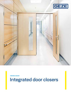
Integrated door closers
SWING DOOR Integrated door closers INTEGRATED DOOR CLOSERS Contents Overview 04 FOR S IN GLE LE A F D O O R S Boxer 08 Boxer E with electric hold-open device 14 Boxer P for double-action doors 18 FOR S IN GLE LE A F D O O R S W I T H F R E E S W I N G FUN CTI O N Boxer EFS 24 FOR D OU B LE LE A F D O O R S Boxer ISM with integrated closing sequence control 30 Boxer E-ISM with electric hold-open device 38 FOR D OU B LE LE A F D O O R S W I T H F R E E S W I N G FUN CTI O N Boxer ISM-EFS with electric free swing function on the active leaf 48 BOX E R P IVOT B E A R I N G Integrated pivot bearing for opening restriction or holding open doors without a door closer 56 AC C ES S OR IES RSZ … smoke switch control unit 62 FU RTHE R IN FO R M AT I O N Product information for door closers 66 … 4 Integrated door closers | For single leaf doors | Overview OVERV IE W TA B LE O F I N T EG R AT E D D O O R CLO SER S For single leaf doors Boxer size 2-4 / 2-4 … V Boxer size 3-6 Boxer E size 2-4 Boxer E size 3-6 Boxer EFS Boxer P ● ● ● ● ● ● Barrier-free in accordance with DIN 18040 up to leaf width (max.) in mm EN4 1100 EN4 1100 FSA FSA FSA FL EN4 1100 Closing force acc. to EN 1154 2-4 3-6 2-4 3-6 4-6 2-4 Door leaf width (max.) in mm 1100 1400 1100 1400 1400 1100 Leaf weight (max.) in kg 130 180 130 180 180 80 Closer body integrated in the door leaf ● ● ● ● ● ● Guide rail integrated in the door frame ● ● ● ● ● ● 120° 120° 120° 120° 120° 120° Closing force, adjustable ● ● ● ● ● ● Back check, adjustable ● ● ● ● ● ● Latching action, adjustable ● ● ● ● ● ● Closing speed, adjustable ● ● ● ● ● ● Mechanical hold-open device² ● ● ● ● Approval for fire and smoke protection doors1 POSSIBLE APPLICATIONS Opening angle (max.) FUNCTIONS Electric hold-open device ● Electric hold-open device for free swing ● Mechanical closing sequence control, integrated Flexible opening restrictor ● ● ● ● = yes | … An additional suitability certificate is required with the door for fire and smoke protection doors. | … Can be retrofitted, not to fire and smoke protection doors | FSA = Hold-open device | FSA FL = Hold-open device with free swing Overview | For double leaf doors | Integrated door closers OV E RV IE W TA B LE O F I N T EG R AT E D D O O R CLO SERS For double leaf doors Boxer ISM Boxer E-ISM Boxer ISM-EFS ● ● ● EN4 1100 FSA FSA FL Closing force acc. to EN 1154 2-4/3-6 2-4/3-6 4-6/3-6 (2-4) Door leaf width (max.) in mm 1100/1400 1100/1400 1400/1400 (1100) 130/180 130/180 180/180 (130) Approval for fire and smoke protection doors1 Barrier-free in accordance with DIN 18040 up to leaf width (max.) in mm Leaf weight (max.) in kg POSSIBLE APPLICATIONS Closer body integrated in the door leaf ● ● ● Guide rail integrated in the door frame ● ● ● 120° 120° 120° Opening angle (max.) FUNCTIONS Closing force, adjustable ● ● ● Back check, adjustable ● ● ● Latching action, adjustable ● ● ● Closing speed, adjustable ● ● ● Mechanical hold-open device² ● Electric hold-open device ● Electric hold-open device for free swing ● Mechanical closing sequence control, integrated ● ● ● Flexible opening restrictor ● ● ● ● = yes | … An additional suitability certificate is required with the door for fire and smoke protection doors. | … Can be retrofitted, not to fire and smoke protection doors | FSA = Hold-open device | FSA FL = Hold-open device with free swing … 6 … SW ING D O OR For single leaf doors Comfort with safety – that is what integrated door closers from GEZE offer. They close your swing doors gently and quietly, and brake the door's swing due to their back check function. You can always count on GEZE Boxer solutions for single leaf swing doors. You determine the closing speed. You can count on the highest level of safety with all integrated door closers. … Integrated door closers | For single leaf doors | Boxer Boxer Integrated door closer for single leaf doors up to 1400 mm leaf width ARE AS OF APP L I CAT I O N Fire and smoke protection doors, proof of suitability for the door required Right and left single-action doors Single-action doors up to 1400 mm leaf width, for door weights up to 180 kg For door leaf thicknesses from 40 mm Integrated installation PR OD U CT F E AT U R ES Closing force of EN2-4 or EN3-6 with variable adjustment Can be used for right and left hand doors without conversion Door closer is embedded in door leaf and frame and fulfils maximum design demands Integrated back check, slows down doors that are thrown open forcefully Hydraulic latching action which accelerates the door shortly before the closed position Closing speed can be individually adjusted All functions can be adjusted when installed Boxer | For single leaf doors | Integrated door closers PR OD U CT S CA LE D R AW I N G 440 31 42 45 42 45 12 20,5 20,7 29,2 20 32 32 240 Closing force 2-4 440 31 40 51 54 51 54 12 20,5 20,7 29,2 20 40 249,8 Closing force 3-6 TEC HN ICAL DATA FO R D O O R CLO SE R Boxer 2-4 door closer Boxer 2-4 2V door closer Boxer 3-6 door closer PRODUCT FEATURES Closing force acc. to EN 1154 Leaf width recommended up to 2–4 2–4 3–6 1100 mm 1100 mm 1400 mm Recommended leaf weight of up to 130 kg 130 kg 180 kg Minimum leaf thickness 40 mm 40 mm 50 mm ● ● Identical design for DIN left and DIN right ● Statements of approval Length Door closer tested acc. to EN 1154 286 mm 286 mm 293 mm Overall depth 32 mm 32 mm 40 mm Height 45 mm 45 mm 54 mm FUNCTIONS Closing force adjustable Yes, with variable adjustment Closing speed adjustable ● Latching action adjustable Yes, via valve Back check integrated Yes, hydraulically adjustable Position of closing force adjustment top Safety valve to prevent intentional damage Valve control for regulating the latching action speed ● = yes | ○ = optional ● - ● - … Integrated door closers | For single leaf doors | Boxer TECHN ICAL DATA FO R G U I D E R A I L Guide rail Boxer 12 mm Guide rail Boxer … mm PRODUCT FEATURES Use on single / double-action door Single-action door Length 440 mm Overall depth 20 mm 31 mm Height 12 mm … mm FUNCTIONS Opening restrictor integrated - Holding open ○ ● = yes | ○ = optional INSTA LLATION D RAW I N G S B OX ER S I Z E 2-4 22 … 95 22 440 9,5 9,5 20,7 … 4,5 7,5 51 … 12 32,5 27 27 240 107,8 20 20 175 99 286 Installation on timber door | … = guide rail offset max. 10 mm 95 440 456 87 16,2 27 43 … 27 7,5 … 43 10 78,5 175 107,8 99 Installation on metal door | … = guide rail offset max. 10 mm 240 286 95 Boxer | For single leaf doors | Integrated door closers B OX ER SI Z E … -6 95 30 440 9,5 9,5 4,5 60 7,5 12 20,7 … 4 30 … 25,5 25 35,5 25 175 103,2 249,8 94,5 293 Installation on timber door | … = guide rail offset max. 10 mm … 34 23,5 … 34 95 440 86,5 457,5 23,5 175 103,2 94,5 Installation on metal door | … = guide rail offset max. 10 mm 249,8 293 87 11 12 Integrated door closers | For single leaf doors | Boxer BOXE R – OR D E R I N FO R M AT I O N Designation Spindle extension Boxer 2-4 door closer closing force EN 2-4 with back check (without guide rail) … mm 099728 … mm 101759 Boxer 2-4 2V door closer closing force EN 2-4 with back check and independent latching action valve smooth latching function also possible, without guide rail) … mm 134448 … mm 134493 … mm 134494 Boxer 3-6 door closer closing force EN 3-6 with back check (without guide rail) … mm 099735 … mm 101761 … mm 101762 Boxer guide rail 12 mm with lever, overall height 12 mm Guide rail Boxer 12 mm with tapered lever, overall height 12 mm Boxer guide rail … mm with lever, overall height … mm Boxer guide rail … mm with lever and mechanical hold-open device, overall height … mm Version ID no. silver-coloured 129213 silver-coloured 184365 acc. to RAL1 135732 silver-coloured 112161 silver-coloured 095141 acc. to RAL1 135689 ACCESSORIES Mechanical hold-open device for standard/T-Stop/Boxer … mm guide rail, retention force adjustable, can be switched on and off, can be overridden 071924 Mechanical hold open unit for Boxer 12 mm guide rail, retention force adjustable, cannot be overridden 129145 Flexible opening restriction for lightweight doors for riveted guide rails, standard guide rail BG and Boxer guide rail … mm 069780 Flexible opening restriction for lightweight doors for Boxer guide rail 12 mm 129343 … surcharge for RAL special colours, see General Notes in the price list. Boxer | For single leaf doors | Integrated door closers MST Medisch Spectrum Twente, Enschede, Benelux (photo: Erwin Kamphuis) 13 14 Integrated door closers | For single leaf doors | Boxer E Boxer E Integrated door closer for single leaf doors with a leaf width of up to 1400 mm with electric hold-open device ARE AS OF APP L I CAT I O N Fire and smoke protection doors, proof of suitability for the door required Right and left single-action doors Single-action doors up to 1400 mm leaf width, for door weights up to 180 kg For door leaf thicknesses from 40 mm Integrated installation Hold-open systems with integrated hold-open function PR OD U CT F E AT U R ES Closing force of EN2-4 or EN3-6 with variable adjustment Can be used for right and left hand doors without conversion Door closer is embedded in door leaf and frame and fulfils maximum design demands Electric hold-open device in the guide rail with hold-open area of 80°-120° Retention force of the hold-open function with variable adjustment Smoke switch control unit can be connected, with a signal that closes the door automatically in the event of a fire Integrated back check, slows down doors that are thrown open forcefully Hydraulic latching action which accelerates the door shortly before the closed position Closing speed can be individually adjusted All functions can be adjusted when installed Boxer E | For single leaf doors | Integrated door closers PR OD U CT S CA LE D R AW I N G 42 83,5 30 440 32 240 Closing force 2-4 440 51 54 92,5 30 31 40 249,8 Closing force 3-6 TEC HN ICAL DATA FO R D O O R CLO SE R Boxer 2-4 door closer Boxer 2-4 2V door closer Boxer 3-6 door closer PRODUCT FEATURES Closing force acc. to EN 1154 Leaf width recommended up to 2–4 2–4 3–6 1100 mm 1100 mm 1400 mm Recommended leaf weight of up to 130 kg 130 kg 180 kg Minimum leaf thickness 40 mm 40 mm 50 mm Identical design for DIN left and DIN right ● Statements of approval Length Door closer tested acc. to EN 1154 286 mm 286 mm 293 mm Overall depth 32 mm 32 mm 40 mm Height 45 mm 45 mm 54 mm FUNCTIONS Closing force adjustable Yes, with variable adjustment Closing speed adjustable ● Latching action adjustable Yes, via valve Back check integrated Yes, hydraulically adjustable Position of closing force adjustment top Safety valve to prevent intentional damage Valve control for regulating the latching action speed ● = yes | ○ = optional ● - ● - 15 Integrated door closers | For single leaf doors | Boxer E TECHN ICAL DATA FO R G U I D E R A I L E guide rail Boxer PRODUCT FEATURES Use on single / double-action door Single-action door Supply voltage 24 V DC IP rating IP 43 Statements of approval Hold-open device tested acc. to EN 1155 Length 440 mm Overall depth 31 mm Height 30 mm FUNCTIONS Holding open Electrical Hold-open function can be switched on and off ● Hold-open function can be overridden ● ● = yes | ○ = optional INSTA LLATION D RAW I N G S B OX ER E SI Z E 2-4 95 22 440 9,5 9,5 4,5 51 7,5 … 30 … 27 27 32,5 107,8 20 98 240 175 99 286 Installation on timber door | … = guide rail offset max. 10 mm B OX ER E SI Z E … -6 … 95 27 440 9,5 9,5 54,5 25,5 16 175 103,2 94,5 Installation on metal door | … = guide rail offset max. 10 mm 249,8 293 Boxer E | For single leaf doors | Integrated door closers BOX E R E – OR DE R I N FO R M AT I O N Designation Spindle extension Boxer 2-4 door closer Closing force EN 2-4 with back check (without guide rail) … mm 099728 … mm 101759 Boxer 2-4 2V door closer Closing force EN 2-4 with back check and independent latching action valve (smooth latching function also available, without guide rail) … mm 134448 … mm 134493 … mm 134494 Boxer 3-6 door closer Closing force EN 3-6 with back check (without guide rail) … mm 099735 … mm 101761 … mm 101762 E guide rail Boxer with lever and electric hold-open device Version ID no. silver-coloured 119640 acc. to RAL2 135775 ACCESSORIES 145311 Flexible opening restrictor for guide rail 1-leaf: TS 5000 E/R/RFS (door leaf installation), Boxer E; 2-leaf: all E/R/ISM variants TS 5000 and Boxer RSZ … smoke switch control unit Smoke switch control unit for all GEZE hold-open devices silver-coloured 181025 white RAL 9016 184195 stainless steel optic¹ 184196 acc. to RAL² 185231 195524 FA GC 170 wireless KIT Set consisting of: … piece GC 171 wireless module for the wireless extension of GEZE hold-open systems GC 171 wireless module for the wireless connection of wireless components (GC 172 wireless smoke detector; GC 173 wireless thermal detector; GC 175 wireless input module) on GEZE hold-open systems anthracite 163051 GC 172 wireless smoke detector for the wireless connection to GEZE hold-open systems, battery-operated with … years battery lifetime, with base, tested in accordance with EN 54-7 and EN 54-25, general construction technique permit for use with all GEZE hold-open systems white RAL 9016 195522 GC 173 wireless thermal detector for the wireless connection to GEZE hold-open systems, battery-operated with … years battery lifetime, with base, tested in accordance with EN 54-7 and EN 54-25, general construction technique permit for use with all GEZE hold-open systems white RAL 9016 195523 GC 175 wireless input module for wireless connection of manual trigger switches to the GEZE GC 171 wireless module, applicable for all GEZE hold-open systems black 163068 GC 152 smoke detector Complete with base, 24 V DC, 20 mA, tested in accordance with EN 54-7, with general official building approval for use with all GEZE hold-open systems, integrated line monitoring, conform with DIN EN 14637 white 139850 acc. to RAL2 170523 GC 153 wireless thermal detector Complete with base, 24 V DC, 20 mA, tested in accordance with EN54-5, with general official building approval for use with all GEZE hold-open systems, integrated line monitoring, conform with DIN EN 14637 white 139881 acc. to RAL2 170524 Manual trigger switch Flush-mounted version for the manual release of electrically controlled hold-open devices including terminating resistor for line monitoring alpine white 116266 Manual trigger switch with glass pane and … interchangeable labels Flush-mounted version for the manual release of electrically controlled hold-open devices including terminating resistor for line monitoring alpine white 120880 Surface-mounted box, single suitable for the AS 500 switch programme … only for dry rooms | … surcharge for RAL special colours, see General Notes in the price list. 120503 17 18 Integrated door closers | For single leaf doors | Boxer P Boxer P Integrated door closer for single leaf double-action doors with a leaf width of up to 1100 mm ARE AS OF APP L I CAT I O N Fire and smoke protection doors, proof of suitability for the door required Right and left double-action doors Double-action doors up to 1100 mm leaf width and 80 kg weight For door leaf thicknesses from 40 mm Integrated installation PR OD U CT F E AT U R ES Adjustable closing force of EN2-4 with variable adjustment Can be used for right and left hand doors without conversion Door closer is embedded in door leaf and frame and fulfils maximum design demands Integrated back check, slows down doors that are thrown open forcefully Hydraulic latching action which accelerates the door shortly before the closed position Closing speed can be individually adjusted All functions can be adjusted when installed Boxer P | For single leaf doors | Integrated door closers PR OD U CT S CA LE D R AW I N G 440 31 42 45 42 45 12 20,5 20,7 29,2 20 240 Boxer P TEC HN ICAL DATA FO R D O O R CLO SE R Boxer 2-4 door closer Boxer 2-4 2V door closer PRODUCT FEATURES Closing force acc. to EN 1154 2–4 Leaf width recommended up to 1100 mm Recommended leaf weight of up to 80 kg Minimum leaf thickness 40 mm Identical design for DIN left and DIN right ● Statements of approval Door closer tested acc. to EN 1154 Length 286 mm Width 32 mm Height 45 mm FUNCTIONS Closing force adjustable Yes, with variable adjustment Closing speed adjustable ● Latching action adjustable Yes, via valve Back check integrated Yes, hydraulically adjustable Position of closing force adjustment Top Safety valve to prevent intentional damage ● ● = yes | ○ = optional TEC HN ICAL DATA FO R G U I D E R A I L Guide rail Boxer 12 mm Guide rail Boxer … mm PRODUCT FEATURES Use on single / double-action door Double-action door Length 440 mm Width 20 mm 31 mm Height 12 mm … mm FUNCTIONS Opening restrictor integrated Holding open Optional Mechanical Hold-open function can be switched on and off - ● Hold-open function can be overridden - ● ● = yes | ○ = optional 19 Integrated door closers | For single leaf doors | Boxer P INSTA LLATION D RAW I N G S B OX ER P S I Z E 2-4 174 440 118 … 8,5 46 … 31 … 23 20,7 46,5 … 70 12 Ø 25 46,5 20 25 106,8 96 29 240 286 Installation on timber door BOXE R P– OR D E R I N FO R M AT I O N Designation Spindle extension Version ID no. Boxer 2-4 door closer Closing force EN 2-4 with back check (without guide rail) … mm 099728 … mm 101759 Boxer 2-4 2V door closer Closing force EN 2-4 with back check and independent latching action valve (smooth latching function also available, without guide rail) … mm 134448 … mm 134493 … mm 134494 Guide rail Boxer 12 mm with lever for double-action doors, overall height 12 mm (only Boxer 2-4) silver-coloured 129344 acc. to RAL1 135733 Guide rail Boxer … mm with lever for double-action doors with mechanical hold-open device, Overall height … mm (only Boxer 2-4) silver-coloured 104246 acc. to RAL1 135731 ACCESSORIES Mechanical hold-open function for standard / T-Stop / Boxer … mm guide rail, retention force adjustable, can be switched on and off, can be overridden 071924 Mechanical hold-open function for Boxer 12 mm guide rail, retention force adjustable, cannot be overridden 129145 Flexible opening restriction for lightweight doors for riveted guide rail, standard guide rail BG and Boxer … mm guide rail 069780 Flexible opening restriction for lightweight doors for Boxer guide rail 12 mm 129343 … surcharge for RAL special colours, see General Notes in the price list. Boxer P | For single leaf doors | Integrated door closers Hotel, Berlin, Germany (photo: Stefan Dauth) 21 22 23 SW ING D O OR For single leaf doors with free swing function For added comfort and safety, the integrated door closer is available with electric free swing function. It can be used to open your single leaf swing door with minimal force. The comfort latching function that locks the door at the end of its free swing area adds an extra feature to the free swing door closer. The system also fulfils discerning design requirements: The door closer is recessed into the door leaf and frame to fit perfectly in your swing door system. 24 Integrated door closers | For single leaf doors with free swing function | Boxer EFS 4-6 Boxer EFS 4-6 Integrated door closer for single leaf doors up to 1400 mm leaf width with electric free swing function ARE AS OF APP L I CAT I O N Fire and smoke protection doors, proof of suitability for the door required Right and left single-action doors Single-action doors up to 1400 mm leaf width and 180 kg leaf weight Integrated installation Hold-open systems with integrated hold-open function with free swing Barrier-free access in accordance with DIN 18040 PR OD U CT F E AT U R ES Closing force of EN 4-6 with variable adjustment Can be used for right and left hand doors without conversion Door closer is embedded in door leaf and frame and fulfils maximum design demands Closing sequence control holds the active leaf in the waiting position until the passive leaf is closed Free swing function means comfortable use of the door with little effort Comfort hold-open function locks the door leaf at the end of the free swing area Smoke switch control unit can be connected, with a signal that closes the door automatically in the event of a fire Integrated back check, slows down doors that are thrown open forcefully Hydraulic latching action which accelerates the door shortly before the closed position Closing speed can be individually adjusted All functions can be adjusted when installed Boxer EFS 4-6 | For single leaf doors with free swing function | Integrated door closers P l e a s e n o t e : According to the general DIBt official building approval for hold-open systems, the use of a manual trigger switch for free swing door closers is compulsory. PR OD U CT S CA LE D R AW I N G Boxer EFS TEC HN ICAL DATA FO R D O O R CLO SE R Boxer EFS 4-6 PRODUCT FEATURES Closing force acc. to EN 1154 Leaf width recommended up to 4-6 1400 mm Recommended leaf weight of up to 180 kg Minimum leaf thickness 50 mm Identical design for DIN left and DIN right Supply voltage IP rating Statements of approval ● 24 V DC IP43 Door closer tested acc. to EN 1154 Hold-open device tested acc. to EN 1155 Length 332 mm Overall depth 40 mm Height 54 mm FUNCTIONS Closing force adjustable ● Closing speed adjustable ● Latching action adjustable Yes, via valve Back check integrated Yes, mechanically in the guide rail Position of closing force adjustment electrical / for free swing function Safety valve to prevent intentional damage Hold-open function integrated ● = yes | ○ = optional ● electrical / for free swing function 25 Integrated door closers | For single leaf doors with free swing function | Boxer EFS 4-6 INSTA LLATION D RAW I N G S B OX ER EFS 31 40 Installation on timber door | … = guide rail offset max. 10 mm … Installation on metal door | … = guide rail offset max. 10 mm 54 … 51 26 Boxer EFS 4-6 | For single leaf doors with free swing function | Integrated door closers BOX E R E FS – O R D E R I N FO R M AT I O N Designation Version ID no. Boxer EFS 4-6 Closing force EN 4-6, with electric free swing function incl. free swing lever with comfort hold-open function 153559 Guide rail Boxer EFS 12 mm Overall height 12 mm, for Boxer EFS 4-6 153560 Guide rail Boxer EFS … mm Overall height … mm, for Boxer EFS 4-6 153571 ACCESSORIES Spindle extension Boxer EFS 4-6 RSZ … smoke switch control unit Smoke switch control unit for all GEZE hold-open devices … mm 153573 … mm 153574 silver-coloured 181025 white RAL 9016 184195 stainless steel optic¹ 184196 acc. to RAL² 185231 195524 FA GC 170 wireless KIT Set consisting of: … piece GC 171 wireless module for the wireless extension of GEZE hold-open systems GC 171 wireless module for the wireless connection of wireless components (GC 172 wireless smoke detector; GC 173 wireless thermal detector; GC 175 wireless input module) on GEZE hold-open systems anthracite 163051 GC 172 wireless smoke detector for the wireless connection to GEZE hold-open systems, battery-operated with … years battery lifetime, with base, tested in accordance with EN 54-7 and EN 54-25, general construction technique permit for use with all GEZE hold-open systems white RAL 9016 195522 GC 173 wireless thermal detector for the wireless connection to GEZE hold-open systems, battery-operated with … years battery lifetime, with base, tested in accordance with EN 54-7 and EN 54-25, general construction technique permit for use with all GEZE hold-open systems white RAL 9016 195523 GC 175 wireless input module for wireless connection of manual trigger switches to the GEZE GC 171 wireless module, applicable for all GEZE hold-open systems black 163068 GC 152 smoke detector Complete with base, 24 V DC, 20 mA, tested in accordance with EN 54-7, with general official building approval for use with all GEZE hold-open systems, integrated line monitoring, conform with DIN EN 14637 white 139850 acc. to RAL2 170523 GC 153 wireless thermal detector Complete with base, 24 V DC, 20 mA, tested in accordance with EN 54-5, with general official building approval for use with all GEZE hold-open systems, integrated line monitoring, conform with DIN EN 14637 white 139881 acc. to RAL2 170524 AS 500 manual trigger switch for the manual release of electrically controlled hold-open devices including terminating resistor for line monitoring alpine white/red AS 500 manual trigger switch (with glass pane and … interchangeable labels) for the manual release of electrically controlled hold-open devices alpine white/red Surface-mounted box, single suitable for the AS 500 switch programme white … only for dry rooms | … surcharge for RAL special colours, see General Notes in the price list. 116266 120880 120503 27 28 29 SW ING D O OR For double leaf doors An integrated door closer with closing sequence control is used to close double leaf doors safely. It guarantees that the active leaf closes after the passive leaf. This ensures that nothing and no one can become trapped. GEZE Boxer solutions available for double leaf swing doors have been designed to optimally match your swing door, and can be individually adjusted. 30 Integrated door closers | For double leaf doors | Boxer ISM Boxer ISM Integrated door closer system for double leaf doors with closing sequence control ARE AS OF APP L I CAT I O N Fire and smoke protection doors, proof of suitability for the door required Double leaf single-action doors Single-action doors up to 2800 mm hinge clearance, 1400 mm leaf width, for door widths up to 180 kg Minimum hinge clearance 1300 mm, minimum width of passive leaf 540 mm For door leaf thicknesses from 40 mm Integrated installation PR OD U CT F E AT U R ES System made of two Boxer door closers and an ISM guide rail Closing force of EN2-4 or EN3-6 with variable adjustment Can be used for right and left hand doors without conversion Door closer is embedded in door leaf and frame and fulfils maximum design demands Closing sequence control holds the active leaf in the waiting position until the passive leaf is closed Hydraulic latching action which accelerates the door shortly before the closed position Closing speed can be individually adjusted Integrated back check, slows down doors that are thrown open forcefully All functions can be adjusted when installed S P ECI A L VER S I O NS: For doors with narrow hinge clearance from 1130 mm (opening angle max. 100°) For doors with small passive leaf from 420 mm (opening angle passive leaf max. 100°) Boxer ISM | For double leaf doors | Integrated door closers PR OD U CT S CA LE D R AW I N G 484 614 31 30 38,5 45 Active leaf 240 42 240 Passive leaf 32 Boxer ISM, closing force 2-4 484 614 31 30 38,5 45 Active leaf 240 42 240 Passive leaf 32 Boxer ISM, closing force 3-6 435 614 31 240 42 Active leaf 32 Boxer ISM for small passive leaf, closing force 2-4 45 30 38,5 240 Passive leaf 31 Integrated door closers | For double leaf doors | Boxer ISM 435 614 31 240 30 38,5 240 Passive leaf 45 42 Active leaf 32 Boxer ISM for small passive leaf, closing force 3-6 435 614 31 240 30 38,5 240 Passive leaf 45 42 Active leaf 32 Boxer ISM for small hinge clearance, closing force 2-4 435 614 31 240 Active leaf 32 Boxer ISM for small hinge clearance, closing force 3-6 45 30 38,5 240 42 32 Passive leaf Boxer ISM | For double leaf doors | Integrated door closers TEC HN ICAL DATA FO R D O O R CLO SE R Boxer 2-4 door closer Boxer 2-4 2V door closer Boxer 3-6 door closer PRODUCT FEATURES Closing force acc. to EN 1154 2–4 2–4 3–6 1100 mm 1100 mm 1400 mm Recommended leaf weight of up to 130 kg 130 kg 180 kg Minimum leaf thickness 40 mm 40 mm 50 mm ● ● ● Leaf width recommended up to Identical design for DIN left and DIN right Statements of approval Length Door closer tested in accordance with EN 1154 286 mm 286 mm 293 mm Overall depth 32 mm 32 mm 40 mm Height 45 mm 45 mm 54 mm FUNCTIONS Closing force adjustable Closing speed adjustable Yes, with variable adjustment ● ● Latching action adjustable Back check integrated Yes, hydraulically adjustable Position of closing force adjustment Safety valve to prevent wilful damage ● Yes, via valve top ● ● Valve control for regulating the latching action speed ● ● TEC HN ICAL DATA FO R G U I D E R A I L ISM guide rail Boxer ISM guide rail Boxer, small hinge clearance variant ISM guide rail Boxer, small passive leaf variant Minimum hinge clearance 1300 mm 1130 mm 1230 mm Minimum passive leaf width 540 mm 420 mm 420 mm PRODUCT FEATURES Statements of approval Closing sequence controller tested acc. to EN 1158 Overall depth 31 mm Height 30 mm FUNCTIONS Closing sequence control integrated ● ● ● Hold-open function integrated ○ ○ ○ ● = yes | ○ = optional 33 Fixed leaf – right leaf Smallest door width B = 1300 mm Largest door width B = 2800 mm GEZE Boxer size 3-6 Dimensions GEZE Boxer size 3-6 Dimensions GEZE Boxer size 2-4 Smallest door width B = 1300 mm Largest door width B = 2200 mm GEZE Boxer size 2-4 Dimensions GEZE Boxer size 2-4 GF = Moving leaf Door opening angle approx. 120° Minimum width of fixed leaf = 540 mm plus space needed for fixed leaf lock Door leaf machining, fixed leaf GEZE Boxer size 2-4 Door leaf machining, moving leaf GEZE Boxer size 2-4 Mirror imaged frame and door machining for left leaf 24V cable (E-ISM) Channel cover, (wire cable/24V cable) Wire cable Frame machining, fixed leaf Door leaf machining, fixed leaf GEZE Boxer size 3-6 Mirror imaged frame and door machining for right leaf Moving leaf – left leaf Concealed 24V power supply E-ISM guide rail / moving leaf = left leaf Concealed 24V power supply E-ISM guide rail / moving leaf = right leaf Integrated door closers Door leaf machining, moving leaf GEZE Boxer size 3-6 Frame machining, moving leaf 34 | For double leaf doors | Boxer ISM IN STALLATION D R AW I N G B OX E R I SM / E- I SM STAN DAR D I N TI M BER DO O R Smallest door width B = 1230 mm Largest door width B = 1940 mm GEZE Boxer size 3-6 Door leaf machining, moving leaf GEZE Boxer size 2-4 Door leaf machining, moving leaf GEZE Boxer size 3-6 Frame machining, moving leaf Dimensions GEZE Boxer size 3-6 Dimensions GEZE Boxer size 2-4 Smallest door width B = 1230 mm Largest door width B = 1640 mm Channel cover, (wire cable/24V cable) Wire cable GEZE Boxer size 2-4 Mirror imaged frame and door machining for right leaf Moving leaf – left leaf Concealed 24V power supply E-ISM guide rail / moving leaf = left leaf Concealed 24V power supply E-ISM guide rail / moving leaf = right leaf Frame machining, fixed leaf Dimensions GEZE Boxer size 2-4 SF = Fixed leaf GF = Moving leaf TÖW = Door opening angle SF door opening angle approx. 120° GF door opening angle approx. 120° SF hold-open angle at approx. 80° - 90° TÖW GF hold-open angle at approx. 80° - 120° TÖW Width of fixed leaf = 420-540 mm plus space needed for fixed leaf lock Door leaf machining, fixed leaf GEZE Boxer size 2-4 Door leaf machining, fixed leaf GEZE Boxer size 3-6 Mirror imaged frame and door machining for left leaf Fixed leaf – right leaf 24V cable (E-ISM) Shown without cover Boxer ISM | For double leaf doors | Integrated door closers IN STA LLATI O N D R AW I N G B OX E R I S M / E- I SM SM ALL PASSI VE LEAF I N TI M BER DO O R 35 Smallest door width B = 1130 mm Largest door width B = 1300 mm GEZE Boxer size 3-6 Door leaf machining, moving leaf GEZE Boxer size 2-4 Dimensions GEZE Boxer size 3-6 Channel cover, (wire cable/24V cable) Wire cable Dimensions GEZE Boxer size 2-4 24V cable (E-ISM) Shown without cover Smallest door width B = 1130 mm Largest door width B = 1300 mm GEZE Boxer size 2-4 Mirror imaged frame and door machining for right leaf Moving leaf – left leaf Concealed 24V power supply E-ISM guide rail / moving leaf = left leaf Concealed 24V power supply E-ISM guide rail / moving leaf = right leaf Fixed leaf – right leaf Dimensions GEZE Boxer size 2-4 Mirror imaged frame and door machining for left leaf SF = Fixed leaf GF = Moving leaf TÖW = Door opening angle FL door opening angle approx. 120° FL hold-open angle at approx. 80° - 90° DOA Minimum width of fixed leaf = 420 mm plus space needed for fixed leaf lock Door leaf machining, fixed leaf GEZE Boxer size 2-4 Door leaf machining, fixed leaf GEZE Boxer size 3-6 Frame machining, fixed leaf Integrated door closers Door leaf machining, moving leaf GEZE Boxer size 3-6 Frame machining, moving leaf 36 | For double leaf doors | Boxer ISM INSTA LLATION D R AW I N G B OX E R I SM / E- I SM SM ALL HI N G E CLEAR AN CE I N TI M BER DO O R Boxer ISM | For double leaf doors | Integrated door closers BOX E R IS M– O R D E R I N FO R M AT I O N Designation Spindle extension Boxer 2-4 door closer Closing force EN 2-4 with back check (without guide rail) … mm Version 099728 ID no. … mm 101759 Boxer 2-4 2V door closer Closing force EN 2-4 with back check and independent latching action valve (smooth latching function also available, without guide rail) … mm 134448 … mm 134493 … mm 134494 Boxer 3-6 door closer Closing force EN 3-6 with back check (without guide rail) … mm 099735 … mm 101761 … mm 101762 ISM guide rail Boxer with integrated closing sequence control and levers silver-coloured 114141 ISM guide rail Boxer version, small hinge clearance especially for small hinge clearances from 1130 mm, with integrated closing sequence control and levers silver-coloured 120894 ISM guide rail Boxer version, small passive leaf especially for doors with small passive leaf from 420 mm, with integrated closing sequence control and levers silver-coloured 128597 ACCESSORIES GEZE flexible opening restrictor for guide rail 1-leaf: TS 5000 E/R/RFS (door leaf installation), Boxer E; 2-leaf: all E/R/ISM variants TS 5000 and Boxer CB flex carry bar for use on all 2-leaf rebated doors. Concealed length adjustment with variable adjustment up to 210 mm leaf protrusion, hinged mechanism not visible, profile can be shortened if necessary, with attachment material Mechanical hold-open function for ISM-guide rail, retention force adjustable, can be overridden … surcharge for RAL special colours, see General Notes in the price list. Only for dry rooms | … surcharge for RAL special colours, see General Notes in the price list. 145311 acc. to RAL1 153728 silver-coloured 153602 118437 37 38 Integrated door closers | For double leaf doors | Boxer E-ISM Boxer E-ISM Integrated door closer system for double leaf doors with closing sequence control and electric hold-open device ARE AS OF APP L I CAT I O N Fire and smoke protection doors, proof of suitability for the door required Double leaf single-action doors Symmetrical and asymmetrical division of door possible Single-action doors up to 2800 mm hinge clearance, 1400 mm leaf width, for door widths up to 180 kg Minimum hinge clearance 1300 mm, minimum width of passive leaf 540 mm For door leaf thicknesses from 40 mm Integrated installation PR OD U CT F E AT U R ES System made of two Boxer door closers and an E- ISM guide rail Closing force of EN 2-4 or EN 3-6 with variable adjustment Can be used for right and left hand doors without conversion Door closer is embedded in door leaf and frame and fulfils maximum design demands Closing sequence control holds the active leaf in the waiting position until the passive leaf is closed Electric hold-open device in the guide rail with hold-open area of 80°-120° Retention force of the hold-open function with variable adjustment Smoke switch control unit can be connected, with a signal that closes the door automatically in the event of a fire Integrated back check, slows down doors that are thrown open forcefully Hydraulic latching action which accelerates the door shortly before the closed position Closing speed can be individually adjusted All functions can be adjusted when installed S P ECI A L VERSI O N S: For doors with narrow hinge clearance from 1130 mm (opening angle max. 100°) For doors with small passive leaf from 420 mm (opening angle passive leaf max. 100°) Boxer E-ISM | For double leaf doors | Integrated door closers PR OD U CT S CA LE D R AW I N G 484 614 31 30 42 Active leaf 38,5 240 Passive leaf 45 240 32 Boxer E-ISM, closing force 2-4 484 614 31 249,8 51 54 30 38,5 249,8 Active leaf Passive leaf 40 Boxer E-ISM, closing force 3-6 435 614 31 240 42 Active leaf 32 Boxer E-ISM for small passive leaf, closing force 2-4 45 30 38,5 240 Passive leaf 39 Integrated door closers | For double leaf doors | Boxer E-ISM 435 614 31 249,8 54 30 51 Active leaf 38,5 249,8 Passive leaf 40 Boxer E-ISM for small passive leaf, closing force 3-6 435 577 31 Passive leaf 45 42 Active leaf 38,5 240 30 240 32 Boxer E-ISM for small hinge clearance, closing force 2-4 435 577 31 249,8 30 38,5 249,8 Active leaf 51 54 40 40 Boxer E-ISM for small hinge clearance, closing force 3-6 Passive leaf Boxer E-ISM | For double leaf doors | Integrated door closers TEC HN ICAL DATA FO R D O O R CLO SE R Boxer 2-4 door closer Boxer 2-4 2V door closer Boxer 3-6 door closer PRODUCT FEATURES Closing force acc. to EN 1154 2–4 2–4 3–6 1100 mm 1100 mm 1400 mm Recommended leaf weight of up to 130 kg 130 kg 180 kg Minimum leaf thickness 40 mm 40 mm 50 mm ● ● ● Leaf width recommended up to Identical design for DIN left and DIN right Statements of approval Length Door closer tested acc. to EN 1154 286 mm 286 mm 293 mm Overall depth 32 mm 32 mm 40 mm Height 45 mm 45 mm 54 mm FUNCTIONS Closing force adjustable Closing speed adjustable Yes, with variable adjustment ● ● Latching action adjustable Back check integrated Yes, hydraulically adjustable Position of closing force adjustment Safety valve to prevent intentional damage ● Yes, via valve top ● ● Valve control for regulating the latching action speed ● ● ● = yes | ○ = optional TEC HN ICAL DATA FO R G U I D E R A I L E-ISM guide rail Boxer E-ISM guide rail Boxer variant, E-ISM guide rail Boxer variant, small hinge clearance small passive leaf PRODUCT FEATURES Minimum hinge clearance 1300 mm 1130 mm 1230 mm Minimum passive leaf width 540 mm 420 mm 420 mm Supply voltage 24 V DC IP rating IP 43 Statements of approval Hold-open device tested acc. to EN 1155 Closing sequence controller tested acc. to EN 1158 Overall depth 31 mm Height 30 mm FUNCTIONS Closing sequence control integrated ● Hold-open function integrated ● ● electrical Hold-open function on active leaf / passive leaf ●/● Hold-open function can be switched on and off ● ● ● Hold-open function can be overridden ● ● ● ● = yes | ○ = optional 41 Fixed leaf – right leaf Smallest door width B = 1300 mm Largest door width B = 2800 mm GEZE Boxer size 3-6 Dimensions GEZE Boxer size 3-6 Dimensions GEZE Boxer size 2-4 Smallest door width B = 1300 mm Largest door width B = 2200 mm GEZE Boxer size 2-4 Dimensions GEZE Boxer size 2-4 GF = Moving leaf Door opening angle approx. 120° Minimum width of fixed leaf = 540 mm plus space needed for fixed leaf lock Door leaf machining, fixed leaf GEZE Boxer size 2-4 Door leaf machining, moving leaf GEZE Boxer size 2-4 Mirror imaged frame and door machining for left leaf 24V cable (E-ISM) Channel cover, (wire cable/24V cable) Wire cable Frame machining, fixed leaf Door leaf machining, fixed leaf GEZE Boxer size 3-6 Mirror imaged frame and door machining for right leaf Moving leaf – left leaf Concealed 24V power supply E-ISM guide rail / moving leaf = left leaf Concealed 24V power supply E-ISM guide rail / moving leaf = right leaf Integrated door closers Door leaf machining, moving leaf GEZE Boxer size 3-6 Frame machining, moving leaf 42 | For double leaf doors | Boxer E-ISM INSTA LLATION D R AW I N G B OX E R I S M / E- I SM STAN DAR D I N TI M BER DO O R Smallest door width B = 1230 mm Largest door width B = 1940 mm GEZE Boxer size 3-6 Door leaf machining, moving leaf GEZE Boxer size 2-4 Door leaf machining, moving leaf GEZE Boxer size 3-6 Frame machining, moving leaf Dimensions GEZE Boxer size 3-6 Dimensions GEZE Boxer size 2-4 Smallest door width B = 1230 mm Largest door width B = 1640 mm Channel cover, (wire cable/24V cable) Wire cable GEZE Boxer size 2-4 Mirror imaged frame and door machining for right leaf Moving leaf – left leaf Concealed 24V power supply E-ISM guide rail / moving leaf = left leaf Concealed 24V power supply E-ISM guide rail / moving leaf = right leaf Frame machining, fixed leaf Dimensions GEZE Boxer size 2-4 SF = Fixed leaf GF = Moving leaf TÖW = Door opening angle SF door opening angle approx. 120° GF door opening angle approx. 120° SF hold-open angle at approx. 80° - 90° TÖW GF hold-open angle at approx. 80° - 120° TÖW Width of fixed leaf = 420-540 mm plus space needed for fixed leaf lock Door leaf machining, fixed leaf GEZE Boxer size 2-4 Door leaf machining, fixed leaf GEZE Boxer size 3-6 Mirror imaged frame and door machining for left leaf Fixed leaf – right leaf 24V cable (E-ISM) Shown without cover Boxer E-ISM | For double leaf doors | Integrated door closers IN STA LLATI O N D R AW I N G B OX E R I SM / E- I SM SM ALL PASSI VE LEAF I N TI M BER DO O R 43 Smallest door width B = 1130 mm Largest door width B = 1300 mm GEZE Boxer size 3-6 Door leaf machining, moving leaf GEZE Boxer size 2-4 Dimensions GEZE Boxer size 3-6 Channel cover, (wire cable/24V cable) Wire cable Dimensions GEZE Boxer size 2-4 24V cable (E-ISM) Shown without cover Smallest door width B = 1130 mm Largest door width B = 1300 mm GEZE Boxer size 2-4 Mirror imaged frame and door machining for right leaf Moving leaf – left leaf Concealed 24V power supply E-ISM guide rail / moving leaf = left leaf Concealed 24V power supply E-ISM guide rail / moving leaf = right leaf Fixed leaf – right leaf Dimensions GEZE Boxer size 2-4 Mirror imaged frame and door machining for left leaf SF = Fixed leaf GF = Moving leaf TÖW = Door opening angle FL door opening angle approx. 120° FL hold-open angle at approx. 80° - 90° DOA Minimum width of fixed leaf = 420 mm plus space needed for fixed leaf lock Door leaf machining, fixed leaf GEZE Boxer size 2-4 Door leaf machining, fixed leaf GEZE Boxer size 3-6 Frame machining, fixed leaf Integrated door closers Door leaf machining, moving leaf GEZE Boxer size 3-6 Frame machining, moving leaf 44 | For double leaf doors | Boxer E-ISM IN STALLATION D R AW I N G B OX E R I SM / E- I SM SM ALL HI N G E CLEARAN CE I N TI M BER DO O R Boxer E-ISM | For double leaf doors | Integrated door closers BOX E R E-IS M– O R D E R I N FO R M AT I O N Designation Spindle extension Boxer 2-4 door closer Closing force EN 2-4 with back check (without guide rail) … mm 099728 … mm 101759 Boxer 2-4 2V door closer Closing force EN 2-4 with back check and independent latching action valve (smooth latching function also available, without guide rail) … mm 134448 … mm 134493 … mm 134494 … mm 099735 … mm 101761 … mm 101762 Boxer 3-6 door closer Closing force EN 3-6 with back check (without guide rail) Version ID no. E-ISM guide rail Boxer With integrated closing sequence control, electric hold-open device on both leaves and levers silver-coloured 114142 E-ISM guide rail Boxer variant, small hinge clearance especially for small hinge clearances from 1130 mm, with integrated closing sequence control, electric hold-open device on both leaves and levers silver-coloured 120895 E-ISM guide rail Boxer variant, small passive leaf especially for doors with small passive leaf from 420 mm, with integrated closing sequence control, electric hold-open device on both leaves and levers silver-coloured 128598 ACCESSORIES Flexible opening restrictor for guide rail 1-leaf: TS 5000 E/R/RFS (door leaf installation), Boxer E; 2-leaf: all E/R/ISM variants TS 5000 and Boxer CB flex carry bar for use on all 2-leaf rebated doors. Concealed length adjustment with variable adjustment up to 210 mm leaf protrusion, hinged mechanism not visible, profile can be shortened if necessary, with attachment material RSZ … smoke switch control unit Smoke switch control unit for all GEZE hold-open devices 145311 acc. to RAL² 153728 silver-coloured 153602 silver-coloured 181025 white RAL 9016 184195 stainless steel optic¹ 184196 acc. to RAL² 185231 195524 FA GC 170 wireless KIT Set consisting of: … piece GC 171 wireless module for the wireless extension of GEZE holdopen systems GC 171 wireless module for the wireless connection of wireless components (GC 172 wireless smoke detector; GC 173 wireless thermal detector; GC 175 wireless input module) on GEZE hold-open systems anthracite 163051 GC 172 wireless smoke detector for the wireless connection to GEZE hold-open systems, battery-operated with … years battery lifetime, with base, tested in accordance with EN 54-7 and EN 54-25, general construction technique permit for use with all GEZE hold-open systems white RAL 9016 195522 GC 173 wireless thermal detector for the wireless connection to GEZE hold-open systems, battery-operated with … years battery lifetime, with base, tested in accordance with EN 54-7 and EN 54-25, general construction technique permit for use with all GEZE hold-open systems white RAL 9016 195523 GC 175 wireless input module for wireless connection of manual trigger switches to the GEZE GC 171 wireless module, applicable for all GEZE hold-open systems black 163068 GC 152 smoke detector Complete with base, 24 V DC, 20 mA, tested in accordance with EN 54-7, with general official building approval for use with all GEZE hold-open systems, integrated line monitoring, conform with DIN EN 14637 white 139850 acc. to RAL2 170523 white 139881 acc. to RAL2 170524 alpine white 116266 GC 153 wireless thermal detector Complete with base, 24 V DC, 20 mA, tested in accordance with EN 54-5, with general official building approval for use with all GEZE hold-open systems, integrated line monitoring, conform with DIN EN 14637 Manual trigger switch Flush-mounted version for the manual release of electrically controlled hold-open devices including terminating resistor for line monitoring 120503 Surface-mounted box, single suitable for the AS 500 switch programme Manual trigger switch with glass pane and … interchangeable labels Flush-mounted version for the manual release of electrically controlled hold-open devices including terminating resistor for line monitoring … Only for dry rooms | … Surcharge for RAL special colours, see General Notes in the price list. alpine white 120880 45 46 47 SW ING D O OR For double leaf doors with free swing function For added comfort and safety, the integrated door closer is available with electric free swing function. It can be used to open your double leaf swing door with minimal force. The comfort latching function that locks the door at the end of its free swing area adds an extra feature to the free swing door closer. The system also fulfils discerning design requirements: The door closer is recessed into the door leaf and frame to fit perfectly in your swing door system. 48 Integrated door closers | For double leaf doors with free swing function | Boxer ISM-EFS Boxer ISM-EFS Integrated door closer system for double leaf doors with closing sequence control and electric free swing function ARE AS OF APP L I CAT I O N Fire and smoke protection doors, proof of suitability for the door required Double leaf single-action doors Symmetrical and asymmetrical division of door possible Single-action doors up to 2800 mm hinge clearance, 1400 mm leaf width, for door widths up to 180 kg Minimum hinge clearance 1300 mm, minimum width of passive leaf 540 mm For door leaf thicknesses from 50 mm Integrated installation Hold-open systems with integrated hold-open function with free swing Barrier-free access in accordance with DIN 18040 PR OD U CT F E AT U R ES System consisting of two door closers Boxer EFS- 4-6 and Boxer 2-4 or 3-6 with ISM guide rail Closing force of EN 4-6 with variable adjustment on the active leaf, EN 3-6 or EN 2-4 on the passive leaf Can be used for right and left hand doors without conversion Door closer is embedded in door leaf and frame and fulfils maximum design demands Closing sequence control holds the active leaf in the waiting position until the passive leaf is closed Free swing function means comfortable use of the door with little effort Comfort hold-open function locks the door leaf at the end of the free swing area Smoke switch control unit can be connected, with a signal that closes the door automatically in the event of a fire Integrated back check, slows down doors that are thrown open forcefully Hydraulic latching action which accelerates the door shortly before the closed position Closing speed can be individually adjusted All functions can be adjusted when installed S P ECI A L VER S I O NS: For doors with small passive leaf from 420 mm (opening angle passive leaf max. 100°) Boxer ISM-EFS | For double leaf doors with free swing function | Integrated door closers PR OD U CT S CA LE D R AW I N G 614 … 484 … (240) Active leaf Passive leaf Boxer ISM-EFS 614 … Active leaf Boxer ISM-EFS for small passive leaf 435 … (240) Passive leaf 49 50 Integrated door closers | For double leaf doors with free swing function | Boxer ISM-EFS TECHN ICAL DATA FO R D O O R CLO SE R Boxer 2-4 door closer Boxer 2-4 2V door closer Boxer 3-6 door closer 2–4 2–4 3–6 Boxer EFS 4-6 PRODUCT FEATURES Closing force acc. to EN 1154 Leaf width recommended up to 1100 mm Recommended leaf weight of up to Minimum leaf thickness Identical design for DIN left and DIN right 4–6 1400 mm 130 kg 180 kg 180 kg 40 mm 40 mm 50 mm 50 mm ● ● ● ● Supply voltage 24 V DC IP rating Statements of approval Length IP 43 Door closer tested acc. to EN 1154 Door closer tested acc. to EN 1154 Door closer tested acc. to EN 1154 Door closer tested acc. to EN 1154 Hold-open device tested acc. to EN 1155 286 mm 286 mm 293 mm 332 mm Overall depth 32 mm 32 mm 40 mm 40 mm Height 45 mm 45 mm 54 mm 54 mm Closing force adjustable Yes, with variable adjustment Yes, with variable adjustment Yes, with variable adjustment Yes, with variable adjustment Closing speed adjustable ● ● ● ● Yes, hydraulically adjustable Yes, hydraulically adjustable Yes, hydraulically adjustable Yes, mechanically in the guide rail ● ● ● ● FUNCTIONS Latching action adjustable Back check integrated Yes, via valve Position of closing force adjustment Safety valve to prevent intentional damage Top Valve control for regulating the latching action speed ● Hold-open function integrated electrically, for free swing function ● = yes | ○ = optional TECHN ICAL DATA FO R G U I D E R A I L ISM guide rail Boxer ISM guide rail Boxer Small passive leaf variant Minimum hinge clearance 1300 mm 1230 mm Minimum passive leaf width 540 mm 420 mm PRODUCT FEATURES Statements of approval Closing sequence controller tested acc. to EN 1158 Overall depth 31 mm Height 30 mm FUNCTIONS Closing sequence control integrated ● = yes | ○ = optional ● ● Smallest door width B = 1335 mm Largest door width B = 2800 mm GEZE Boxer size 3-6 + EFS 4-6 Door leaf machining, active leaf GEZE Boxer EFS 4-6 Alternative positions Connecting terminal 24V DC Frame machining, active leaf Dimensions GEZE Boxer size 3-6 + EFS 4-6 Channel cover, (wire cable/24V cable) Dimensions GEZE Boxer size 2-4 Smallest door width B = 1335 mm Largest door width B = 2500 mm GEZE Boxer size 2-4 + EFS 4-6 Mirror imaged frame and door machining for right leaf Active leaf – left leaf Wire cable Dimensions GEZE Boxer size 2-4 Mirror imaged frame and door machining for left leaf Passive leaf – right leaf GF = Active leaf SF = Passive leaf Door opening angle approx. 110° Minimum width of passive leaf = 540 mm plus space needed for passive leaf lock Door leaf machining, passive leaf GEZE Boxer 2-4 Door leaf machining, passive leaf GEZE Boxer 3-6 Frame machining, passive leaf Boxer ISM-EFS | For double leaf doors with free swing function | Integrated door closers IN STA LLATION D R AW I N G B OX E R I S M - EFS STAN DAR D I N TI M BER DO O R 51 Alternative positions Connecting terminal 24V DC Smallest door width B = 1230 mm Largest door width B = 2800 mm GEZE Boxer size 3-6 + EFS 4-6 Dimensions GEZE Boxer size 3-6 + EFS 4-6 Connecting terminal Dimensions GEZE Boxer size 2-4 Smallest door width B = 1230 mm Largest door width B = 2500 mm GEZE Boxer size 2-4 + EFS 4-6 Mirror imaged frame and door machining for right leaf Active leaf – left leaf Channel cover, (wire cable) Wire cable Dimensions GEZE Boxer size 2-4 Mirror imaged frame and door machining for left leaf Passive leaf – right leaf GF = Active leaf SF = Passive leaf TÖW = Door opening angle Door opening angle GF approx. 100° Door opening angle SF approx. 110° Minimum width of passive leaf = 420-540 mm plus space needed for passive leaf lock Door leaf machining, passive leaf GEZE Boxer 2-4 Door leaf machining, passive leaf GEZE Boxer 3-6 Frame machining, passive leaf Integrated door closers Door leaf machining, active leaf GEZE Boxer EFS 4-6 Frame machining, active leaf 52 | For double leaf doors with free swing function | Boxer ISM-EFS INSTA LLATION D RAW I N G B OX E R I SM - E FS SM ALL PASSI VE LEAF I N TI M BER DO O R Boxer ISM-EFS | For double leaf doors with free swing function | Integrated door closers BOX E R IS M-E FS– O R D E R I N FO R M AT I O N Designation Spindle extension Version ID no. Boxer EFS 4-6 Closing force EN 4-6, with electric free swing function incl. free swing lever with comfort lock function … mm 153559 Spindle extension Boxer EFS 4-6 … mm 153573 … mm 153574 Boxer 2-4 door closer Closing force EN 2-4 with back check (without guide rail) … mm 099728 … mm 101759 Boxer 2-4 2V door closer Closing force EN 2-4 with back check and independent latching action valve (smooth latching function also available, without guide rail) … mm 134448 … mm 134493 … mm 134494 Boxer 3-6 door closer Closing force EN 3-6 with back check (without guide rail) … mm 099735 … mm 101761 … mm 101762 ISM guide rail Boxer with integrated closing sequence control and levers silver-coloured 114141 ISM guide rail Boxer small passive leaf variant especially for doors with small passive leaf from 420 mm, with integrated closing sequence control and levers silver-coloured 128597 ACCESSORIES Flexible opening restrictor for guide rail 1-leaf: TS 5000 E/R/RFS (door leaf installation), Boxer E; 2-leaf: all E/R/ISM variants TS 5000 and Boxer 145311 CB flex carry bar for use on all 2-leaf rebated doors. Concealed length adjustment with variable adjustment up to 210 mm leaf protrusion, hinged mechanism not visible, profile can be shortened if necessary, with attachment material acc. to RAL² 153728 silver-coloured 153602 RSZ … smoke switch control unit Smoke switch control unit for all GEZE hold-open devices silver-coloured 181025 white RAL 9016 184195 stainless steel optic¹ 184196 acc. to RAL² 185231 195524 FA GC 170 wireless KIT Set consisting of: … piece GC 171 wireless module for the wireless extension of GEZE holdopen systems GC 171 wireless module for the wireless connection of wireless components (GC 172 wireless smoke detector; GC 173 wireless thermal detector; GC 175 wireless input module) on GEZE hold-open systems anthracite 163051 GC 172 wireless smoke detector for the wireless connection to GEZE hold-open systems, battery-operated with … years battery lifetime, with base, tested in accordance with EN 54-7 and EN 54-25, general construction technique permit for use with all GEZE hold-open systems white RAL 9016 195522 GC 173 wireless thermal detector for the wireless connection to GEZE hold-open systems, battery-operated with … years battery lifetime, with base, tested in accordance with EN 54-7 and EN 54-25, general construction technique permit for use with all GEZE hold-open systems white RAL 9016 195523 GC 175 wireless input module for wireless connection of manual trigger switches to the GEZE GC 171 wireless module, applicable for all GEZE hold-open systems black 163068 GC 152 smoke detector Complete with base, 24 V DC, 20 mA, tested in accordance with EN 54-7, with general official building approval for use with all GEZE hold-open systems, integrated line monitoring, conform with DIN EN 14637 white 139850 GC 153 wireless thermal detector Complete with base, 24 V DC, 20 mA, tested in accordance with EN 54-5, with general official building approval for use with all GEZE hold-open systems, integrated line monitoring, conform with DIN EN 14637 white Manual trigger switch Flush-mounted version for the manual release of electrically controlled hold-open devices including terminating resistor for line monitoring alpine white according to RAL² 170523 according to RAL² 170524 Replacement glass pane for manual trigger switch 120880 and 120881 … Only for dry rooms | … Surcharge for RAL special colours, see General Notes in the price list. 116266 120503 Surface-mounted box, single suitable for the AS 500 switch programme Manual trigger switch with glass pane and … interchangeable labels Flush-mounted installation for the manual release of electrically controlled hold-open devices 139881 alpine white 120880 10994 53 54 55 SW ING D O O R Boxer pivot bearing Integrated pivot bearing for opening restriction or hold-open function for doors without a door closer 56 Integrated door closers | Boxer pivot bearing Boxer pivot bearing Integrated pivot bearing for opening restriction or hold-open function for doors without a door closer ARE AS OF APP L I CAT I O N Right and left single- and double-action doors Opening restriction for single- or double-action doors without door closer Door systems without smoke and fire protection needs For combining an automatic swing door drive with a Boxer on double leaf door systems PR OD U CT F E AT U R ES Holds doors open without door closer, not self-locking The door opening angle is limited and a door stopper is usually no longer required Doing without door stoppers enhances the appearance of the door area, stumbling hazards and dirty corners disappear Can be used for right and left hand doors without conversion Crushing between door leaf and floor mounted door stopper is avoided Boxer pivot bearing | Integrated door closers PR OD U CT S CA LE D R AW I N G Boxer pivot bearing IN STA LLATION I N FO R M AT I O N Pivot bearing with short cover plate Pivot bearing with long cover plate 57 58 Integrated door closers | Boxer pivot bearing BOXE R P IVOT B E A R I N G - O R D E R I N FO R M ATI O N Designation Spindle extension Boxer pivot bearing Integrated pivot bearing for opening restriction or holding open of doors without door closer, for use with all Boxer guide rails 0, 2, 4, 6, … mm Version ID no. 156278 Boxer guide rail 12 mm with lever, overall height 12 mm silver-coloured 129213 according to RAL1 135732 Boxer guide rail 12 mm with lever for double-action doors, overall height 12 mm (only Boxer 2-4) silver-coloured 129344 according to RAL1 135733 Guide rail Boxer 12 mm with tapered lever, overall height 12 mm silver-coloured 184365 acc. to RAL1 135732 Boxer guide rail … mm with lever, overall height … mm silver-coloured 112161 Boxer guide rail … mm with lever and mechanical hold-open device, overall height … mm silver-coloured 95141 according to RAL1 135689 Boxer guide rail … mm with lever for double-action doors and mechanical hold-open device, overall height … mm (only Boxer 2-4) silver-coloured 104246 according to RAL1 135731 ACCESSORIES Flexible opening restriction for lightweight doors for Boxer guide rail 12 mm 129343 Flexible opening restriction for lightweight doors for riveted guide rail, standard guide rail BG, standard guide rail and Boxer … mm guide rail 069780 Mechanical hold-open function for Boxer 12 mm guide rail, retention force adjustable, cannot be overridden 129145 Mechanical hold-open function for standard / T-Stop / Boxer … mm guide rail, retention force adjustable, can be switched on and off, can be overridden 071924 … Surcharge for RAL special colours, see General Notes in the price list. Boxer pivot bearing | Integrated door closers Vitra Haus, Weil am Rhein, Germany (photo: Oliver Look) 59 60 61 SW ING D O OR Accessories To make your hold-open devices even safer in an emergency, we have a wide range of accessories in our product range. For example, you can opt for a GEZE smoke switch control unit. Manual or wireless – we have numerous versions on offer for you. We are more than happy to answer any questions you may have about your safe door. 62 INTEGRATED DOOR CLOSERS | Accessories | RSZ … SMOKE SWITCH CONTROL UNIT RSZ … smoke switch control unit Extendable smoke switch control unit for all GEZE hold-open devices ARE AS OF APP L I CAT I O N Approved for all GEZE hold-open devices for the early detection of fire and smoke Difficult lintel situations, for example with too little space above the smoke chamber Installation above the active leaf on the vertical wall Installation possible with surface-mounted line-feed PR OD U CT F E AT U R ES Telescopic function for bridging overhangs of up to 30 mm Connection to 230 V power supply and 24 V DC supply of the hold-open device Power supply of the hold-open system is interrupted in the case of an alarm and the doors close Integrated smoke switch with automatic adaptation of the alarm threshold Compensates for light contamination of the smoke chamber and thus increases the service life Visual display of the current control panel status Additional smoke switches can be connected Surface-mounted line-feed possible VIDEO RSZ … SMOKE SWITCH CONTROL UNIT | Accessories | INTEGRATED DOOR CLOSERS PR OD U CT S CA LE D R AW I N G 347 293 27 124 33 30 14 55 … 3 … 4 … = threaded hole M5 | … = opening for additional connections | … = power supply (230 V) | … = threaded hole M5 O R D E R IN FOR M AT I O N Designation Version ID no. RSZ … smoke switch control unit Smoke switch control unit for all GEZE hold-open devices silver-coloured 181025 white RAL 9016 184195 stainless steel optic¹ 184196 acc. to RAL² 185231 ACCESSORIES 195524 FA GC 170 wireless KIT Set consisting of: … piece GC 171 wireless module for the wireless extension of GEZE hold-open systems GC 171 wireless module for the wireless connection of wireless components (GC 172 wireless smoke detector; GC 173 wireless thermal detector; GC 175 wireless input module) on GEZE hold-open systems anthracite 163051 GC 172 wireless smoke detector for the wireless connection to GEZE hold-open systems, battery-operated with … years battery lifetime, with base, tested in accordance with EN 54-7 and EN 54-25, general construction technique permit for use with all GEZE hold-open systems white RAL 9016 195522 GC 173 wireless thermal detector for the wireless connection to GEZE hold-open systems, battery-operated with … years battery lifetime, with base, tested in accordance with EN 54-7 and EN 54-25, general construction technique permit for use with all GEZE hold-open systems white RAL 9016 195523 GC 175 wireless input module for wireless connection of manual trigger switches to the GEZE GC 171 wireless module, applicable for all GEZE hold-open systems black 163068 GC 152 smoke detector Complete with base, 24 V DC, 20 mA, tested in accordance with EN 54-7, with general official building approval for use with all GEZE hold-open systems, integrated line monitoring, conform with DIN EN 14637 white 139850 according to RAL² 170523 GC 153 wireless thermal detector Complete with base, 24 V DC, 20 mA, tested in accordance with EN54-5, with general official building approval for use with all GEZE hold-open systems, integrated line monitoring, conform with DIN EN 14637 white 139881 according to RAL² 170524 Manual trigger switch for the manual release of electrically controlled hold-open devices including terminating resistor for line monitoring alpine white/red 116266 Surface-mounted box, single suitable for the AS 500 switch programme Manual trigger switch with glass pane and … interchangeable labels for the manual release of electrically controlled hold-open devices … Only for dry rooms | … Surcharge for RAL special colours, see General Notes in the price list. 120503 alpine white/red 120880 63 64 65 SW ING D O OR Further information Product information for door closers 66 Integrated door closers | Further information | Product information for door closers Product information for door closers P R O DU CT I N FO R M ATION FOR DOOR CLOSERS Due to the liability the manufacturer has for its products under the German product liability law (§ … Prod-HaftG), the following information regarding door closers for swing doors must be observed. Failure to comply releases the manufacturer from his statutory liability. 1) PRODUCT INFORMATION AND USE AS INTENDED Within this context, door closers are to be defined as products for closing swing doors after they have been opened manually. The closing action is dampened using a hydraulically adjustable feature. The level of closing force required for specific leaf widths is defined in EN 1154. In the case of non-standard applications, the details provided by the manufacturer are to be regarded as definitive. Door closers are used on installed swing doors made from metal, timber or plastic and combinations thereof. When used on smoke and fire protection doors or other standardised self-locking doors, they are subject to strict requirements in terms of the type of installation and their position. Any deviation from these requirements constitutes improper use. Proper use of door closers (use as intended) relies on doors being installed perpendicular and their being able to move smoothly; it is also dependent on the door closers being properly secured. The products must be installed and adjusted professionally in accordance with the manufacturer’s specifications. Where local conditions are particularly unfavourable (wind), door closers with higher torques must be used. It is particularly important to use door closers with a back check function on swing doors that are exposed to wind when opening outwards. The back check function helps protect people, door elements, nearby walls and objects, without restricting the door opening angle. If the structural conditions of the door are such that there is a risk of the door leaf hitting the frame in the vicinity of the door’s axis of rotation, a buffer must be installed to limit the door’s maximum opening angle. If swing doors are to be fixed in the open position, this may only be achieved using special additional fittings or integrated constructional elements. When used on smoke and fire protection doors, the devices must be officially approved by Deutsches Institut für Bautechnik (German Centre of Competence for Construction) (door suitability certificates must be heeded). Door closers are not suitable for installation on swing doors in the case of exposed exterior installation or for installation in environments where the air contains aggressive, corrosive substances or in extremely high or low temperatures. Following installation, enclosures for floor springs must be protected against soiling. If floor springs are exposed to penetrating water such as wet rooms or exterior doors with no protection from the rain, the area between the cement box and the floor spring cover must be sealed with a suitable sealing compound. Compliance with mandatory statutory provisions must be ensured, where applicable, before door closers (including any additional devices) are installed and commissioned. 2) MISUSE Misuse (i.e. improper use of door closer products for swing doors) includes, in particular: the presence of obstacles in the closing area, scraping doors, sticking seals, wooden wedges, etc. that hinder the door’s closing action, if incorrect or improper mounting and/or adjustment occurs, if reaching into the area between the door frame and leaf (risk of injury), if the warranted properties are likely to trigger proper functioning, e.g. in case of storms or unusual levels of overpressure or underpressure acting on the door, if door closers are used for any purpose other than closing doors, if the selected closing force does not tally with the manufacturer's recommendations. 3) PRODUCT PERFORMANCE Where catalogues, brochures, manuals, etc. do not contain specific details of product performance, special requirements must be discussed and agreed with the manufacturer. The EN 1154 standards serve as a guideline. These standards stipulate the vast majority of basic and additional requirements. Amongst other things, the usability of door closers depends on how often they are operated, how they are operated, environmental influences and how they are cared for. Door closers must be replaced as soon as the door's closing action can no longer be guaranteed to be fault-free and reliable. Product information for door closers | Further information | Integrated door closers 4) PRODUCT MAINTENANCE 5) DUTIES TO INFORM AND INSTRUCT Safety-related components of door closers must be checked regularly for tightness and signs of wear (depending on what the requirements are). Fixing screws must be re-tightened and defective components replaced. In addition, the following maintenance work must be carried out at least once a year (depending on the swing door type and extent of use). The following resources are available to help planners, specialist suppliers, installation companies, builders and users fulfil their duties of information and instruction: Grease all moving parts on the link arm. In the case of door closers with special functions (hold-open devices and hold-open systems), ensure compliance with statutory inspections, monitoring requirements and suggested maintenance intervals. Check the door closer settings e.g. the closing speed. Check that the door is able to move easily. Do not use any cleaning agents that contain corrosive or damaging ingredients. Andels Hotel, Berlin, Germany (photo: Stefan Dauth) Catalogues, brochures, leaflets, Tender texts and bidding documents, Attachment instructions, installation drawings, operating instructions, standards Advice from field staff. To ensure correct use of door closers on swing doors, guarantee their function and make sure they are maintained and cared for appropriately: Architects and planners are advised to order and observe the necessary product information, Specialist suppliers are advised to observe the product information and advice in the price lists and, in particular, to order all relevant instructions, which are to be passed on to the installation engineer, fabrication companies are advised to observe all the product, information and to pass it on to the client and user. 67 We are GEZE. For liveable buildings GEZE stands for innovation, high quality and comprehensive support of building technologies. From the initial idea, planning and operational implementation with standard products to customised system solutions and individual service and maintenance plans. We offer an extensive product range of door, window and safety technology products and are a major driving force behind the digital networking of building automation. GEZE GmbH Reinhold-Vöster-Strasse 21 – 29 71229 Leonberg Germany Telephone: +49 7152 203 … Fax: +49 7152 203 310 E-Mail: info.de@geze.com www.geze.com 2023_01 ID no. 091609 EN Subject to change without notice
PDF | 4 MB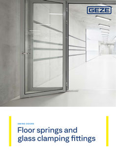
Floor springs and all-glass fittings
SWING DOORS Floor springs and glass clamping fittings Contents | Floor springs andglass clamping fi t tings Contents Overview 04 FOR S IN GLE LE A F SI N G LE A N D D O U B LE-ACTI O N DO O R S TS 500 NV 08 TS 500 N EN3 14 TS 550 NV 20 TS 550 NV F 26 ACC ES S OR IES Accessories for floor springs 34 RSZ … smoke switch control unit 46 GLAS S CLAMP I N G F I TT I N G S GEZE Glass Fittings 50 Corner fittings and pivot bearings 52 Fanlight and connecting fittings 55 Locks and strike boxes 58 M OD U LA R FIX E D PA N E L P R O F I LE SYST EMS Fixed panel profile with clip-on cover profile design 40 64 … Floor springs andglass clamping fit tings | Overview TS 500 N EN … TS 550 NV F Max. door leaf width (mm) 1100 TS 550 NV ● TS 500 N EN3 with hold-open function Approval for fire and smoke protection doors TS 500 NV with hold-open function OVERV IE W TS 500 NV … 950 1400 1400 ● 1100 950 ● APPLICATION POSSIBILITIES: Single-action doors (right/left) ● ● ● ● ● ● Opening angle 170° 170° 170° 170° 170° 180° Double-action doors ● ● ● ● ● Leaf weight up to kg 150 150 100 100 300 300 ● ● EN … fix EN … fix ● ● ● ● ● ● FUNCTIONS: Closing force, adjustable Back check, fixed ● ● Hydraulic latching action, adjustable ● ● Closing speed, adjustable ● ● ● ● ● ● ● ● Mechanical hold-open function ● ● ● Hold-open angle 85° 90° 105° 120° 85° 90° 105° 120° 85° 165° ● = yes TABLE S HOWIN G T H E R AT I O O F CLO S I N G FO RCE TO DO O R LEAF W I DTH Closing force Door leaf width (mm) Size … up to 850 Size … over 850 up to 950 Size … over 950 up to 1100 Size … over 1100 up to 1250 Size … over 1250 up to 1400 C OV ER PLATES There are various cover plates with screw accessories available for floor springs. These can be used on the right, left and with double-action doors. P I VOT H I N GES / D OOR RAILS Special upper pivots and door rails with 36 mm pivot point distance are required for the installation of a floor spring on single-action doors. (See accessories for floor springs from page 32) T HE REQU I REMEN TS The standard (EN 1154) stipulates that the door closer size (closing force) must be set to match the door leaf width. The next higher size has to be set if the structural circumstances (door height, door weight) or local conditions (wind influence) make this necessary. T HE G EZ E S O LUTI ON The floor spring - versions of the TS 500 NV and TS 550 NV series comprise several sizes in one housing. Using an adjustment screw, the corresponding closing force can easily be adapted to the structural and local circumstances. … 6 … SW ING D O O R S For single leaf single and double-action doors Almost invisible, yet fully functional: Floor springs ensure that your doors will close themselves after opening. They’re just as good as overhead door closers where convenience and safety are concerned. All individual parts are built into the floor or the door. Floor springs are ideal when the door design should be as unobtrusive as possible – be it at elegant portals or in upmarket shop fittings. They master this particular challenge for semicircular arched doors or all-glass doors as a single system – and with flair at that. … Floor springs andglass clamping fit tings | For single leaf single and double-action doors | TS 500 NV TS 500 NV Floor spring for single leaf single and double-action doors of up to 1100 mm leaf width with adjustable closing force EN 1-4 and with optional hold-open function ARE AS OF APPLI CATI O N Fire and smoke protection doors Right and left single- and double-action doors Single- and double-action doors up to 1100 mm leaf width and 150 kg weight Hidden horizontal floor installation PR OD U CT FE AT U R ES Adjustable closing force of EN1-4 Can be used for right and left hand doors without conversion Closing speed can be individually adjusted Hydraulic latching action which accelerates the door shortly before the closed position Integrated back check, slows down doors that are thrown open forcefully All functions can be adjusted from the top and when installed V E R S ION S TS 500 NV with hold-open function: mechanical hold-open function in door closer with hold-open area of 85°/90°/105°/120° for single-action doors and hold-open area of 90°/95°/110°/125° for double-action doors (not permissible for use on fire and smoke protection doors) TS 500 NV | For single leaf single and double-action doors | Floor springs andglass clamping fi t tings TEC HN ICAL DATA FO R F LO O R SP R I N G S TS 500 NV TS 500 NV with hold-open function yes no PRODUCT FEATURES Suitability for fire protection doors Use on single-action/double-action door single-action door, double-action door Barrier-free in accordance with DIN 18040 up to leaf width (max.) in mm 1100 mm - Type of installation floor Opening angle (max.) 170° Closing force acc. to EN 1154 EN … – … Leaf width (max.) 1100 mm Leaf weight (max.) 150 kg DIN/ISO direction left/right Product tested in accordance with door closer tested acc. to EN 1154 Length 278 mm Overall depth 82 mm Height 42 mm Length adjustment range for cement box 10 mm Width adjustment range for cement box 10 mm Height adjustment range for cement box … mm FUNCTIONS Closing force adjustable yes, with variable adjustment Closing speed adjustable yes Latching action adjustable yes, via valve Back check integrated yes, mechanical, fixed Delayed closing integrated no Position of closing force adjustment top Holding open no mechanical Single-action door hold-open area - 85°, 90°, 105°, 120° Double-action door hold-open area - 90°/95°/110°/125° Safety valve to prevent wilful damage yes Closing sequence control integrated no Thermo-constant valves yes Closing effect from 170° ● = yes | - = not available … 2 … 4 … = Latching action setting | … = Closing speed setting | … = Closing force setting | … = Frontal gearing pivot … Floor springs andglass clamping fit tings | For single leaf single and double-action doors | TS 500 NV PRODU CT S CALE D R AW I N G 42 TS … 0 … N V 278 298 36-46 36-46 82 105 51-61 STAN DA R D IN STALLAT I O N Example of door rail, upper pivot and floor spring installation on a single-action door (aluminium): A-A 36 B-B 51 A A 36 278 B H S 82 B 42 10 Door rail model DB, EK, FK for single-action doors H = Installation height dimension With elongated pivots, the installation height dimension "H" is increased by the respective spindle extension Model S H DB, EK, FK 10 mm 24 mm TS 500 NV | For single leaf single and double-action doors | Floor springs andglass clamping fi t tings Example of door rail, upper pivot and floor spring installation on a double-action door: C A A-A 175 … X … 28 … 31 46 C-C Y 84 75 … 85 R8 135 254 48 … B 53 OKFF 42 … 6 23 B (26) 82 R8 10,62 15 A 7,5 C R8 278 TS 500 NV / TS 500 N EN3 … 25 31 30 R 21 52 50 ° B-B R8 … 15 15 H S … = Pivot hinge upper part | … = Pivot hinge lower part | … = Adjustment range 51 – 61 | … = Cover plate notched | … = Cover plates - cap shortened | OKFF = Finished floor level Door rail model CM, C for double-action doors With elongated pivots, the installation height dimension "H" is increased by the respective spindle extension Model S H CM 19 mm 29 mm C 19 mm 29 mm 11 12 Floor springs andglass clamping fit tings | For single leaf single and double-action doors | TS 500 NV TS 500 N V – OR D E R I N FO R MAT I O N Designation TS 500 NV door closer Size EN 1-4, optionally with fixed mechanical hold-open function (without cover plate and accessories) DIN Direction Hold-open single action Hold-open double-action Version left/right 0° 0° silver-coloured 102084 left/right 85° 90° silver-coloured 103974 ID no. left/right 90° 95° silver-coloured 104028 left/right 105° 110° silver-coloured 104029 left/right 120° 125° silver-coloured 104030 Floor spring cover plate for TS 500 NV / TS 500 N EN3 brass 103012 stainless steel 102127 TS 500 N V – OR D E R I N FO R MAT I O N Designation DIN Direction Spindle extension Version ID no. left stainless steel optic 137586 left EV1 006794 right stainless steel optic 137577 right EV1 006798 left stainless steel optic 137618 left EV1 045196 right stainless steel optic 137617 right EV1 045155 Cover caps for pivot hinges (flush-mounted doors) suitable for models DB, EK, FK left/right EV1 001090 left/right stainless steel optic 137640 Cover caps for pivot hinges (rebated doors) suitable for models DB, EK, FK left stainless steel optic 137641 left EV1 037918 right EV1 038302 right stainless steel optic 137642 ACCESSORIES Cover caps for door rails (flush-mounted doors) suitable for models DB, EK, FK Cover caps for door rails (rebated doors) suitable for models DB, EK, FK Spindle cap for floor spring … with flat cone, including clamping-extension bolt Spindle cap for floor spring with square for double-action doors, including clamping-extension bolt left/right … mm 050644 left/right … mm 010337 left/right … mm 050930 left/right 10 mm 010338 left/right 13 mm 052170 left/right 15 mm 010347 left/right 20 mm 010372 left/right 25 mm 010373 left/right 28 mm 050931 left/right 30 mm 010374 left/right 35 mm 010377 left/right 40 mm 010378 left/right 45 mm 010381 left/right 50 mm 010385 … mm 053315 TS 500 NV | For single leaf single and double-action doors | Floor springs andglass clamping fi t tings TS … 0 … N V – O R D E R I N FO R MAT I O N Designation Spindle cap for floor spring … with square for single-action doors, including clamping-extension bolt DIN Direction Spindle extension left … mm 053954 right … mm 053955 left … mm 053956 right … mm 053957 left 10 mm 053958 right 10 mm 053959 left 15 mm 053960 right 15 mm 053961 left 20 mm 053962 right 20 mm 053963 left 25 mm 053964 right 25 mm 053965 Version ID no. Door rail for double-action doors Model C, for metal and timber doors flat cone 007432 Door rail for double-action doors Model CM, for metal doors, on-site adaptation to profile system, without surface treatment galvanised 021817 Door rail for double-action doors Model CM, for metal doors, adapted to profile system flat cone 001067 Door rails for single-action doors Model DB, for rebated & flush-impact metal and wooden doors flat cone 044579 square 037581 Door rails for single-action doors Model EK, for welding to steel doors flat cone 008269 square 006696 Door rails for single-action doors Model FK, for welding for steel doors flat cone 008270 square 006699 flat cone 007434 Door rail for double-action doors Model S, for welding to steel doors Adjustable pivot hinge for double-action doors Model B, suitable for C, CM, S door rails Adjustable pivot hinge for double-action doors Model C, suitable for C, CM, S door rails Pivot hinge for single-action doors* Model DB, for rebated & flush-impact metal and wooden doors Pivot hinge for single-action doors* Model EK, for welding to steel doors Pivot hinge for single-action doors* Model FK, for welding for steel doors pivot pin 43 mm 006371 pivot pin 55 mm 000108 pivot pin 65 mm 000903 pivot pin 43 mm 006666 pivot pin 55 mm 000905 pivot pin 65 mm 000904 combination a 044676 combination b DIN left 044697 combination b DIN right 044680 combination c 044787 combination a 006719 combination b DIN left 000889 combination b DIN right 000890 combination c 000891 combination a 006724 combination b DIN left 000895 combination b DIN right 000896 combination c 000897 … It may be necessary to use a longer pivot depending on the installation situation. This is a simple process for all floor-mounted door closer versions in the TS 500 NV/TS 550 NV series by unscrewing the standard pivot and attaching the longer pivot. *For more detailed information about the combination options see page 35 ff. 13 14 Floor springs andglass clamping fit tings | For single leaf single and double-action doors | TS 500 N EN3 TS 500 N EN3 Floor spring for single leaf single and double-action doors of up to 950 mm leaf width with fixed closing force EN3 and with optional hold-open function ARE AS OF APPLI CATI O N Fire and smoke protection doors Right and left single- and double-action doors Single- and double-action doors up to 950 mm leaf width and 100 kg weight Hidden horizontal floor installation PR OD U CT FE AT U R ES Fixed closing force of EN3 Can be used for right and left hand doors without conversion Closing speed can be individually adjusted Hydraulic latching action which accelerates the door shortly before the closed position Integrated back check, slows down doors that are thrown open forcefully All functions can be adjusted from the top and when installed V E R S ION S TS 500 N EN3 with hold-open function: with fixed closing force of EN3 and mechanical hold-open function in the door closer with hold-open area of 85°/90°/105°/120° for single-action doors and hold-open area of 90°/95°/110°/125° for double-action doors (not permissible for use on fire and smoke protection doors) TS 500 N EN3 | For single leaf single and double-action doors | Floor springs andglass clamping fi t tings TEC HN ICAL DATA FO R F LO O R SP R I N G S PRODUCT FEATURES Headline 30Pt neg undo from template Suitability for fire protection doors Use on single-action/double-action door TS 500 N EN3 TS 500 N EN3 with hold-open function yes no single-action door, double-action door Barrier-free in accordance with DIN 18040 up to leaf width (max.) in mm 950 mm Type of installation floor Opening angle (max.) 170° Closing force acc. to EN 1154 EN … Leaf width (max.) 950 mm Leaf weight (max.) 100 kg DIN/ISO direction left/right Product tested in accordance with door closer tested acc. to EN 1154 Length 278 mm Overall depth 82 mm Height 42 mm Length adjustment range for cement box 10 mm Width adjustment range for cement box 10 mm Height adjustment range for cement box … mm FUNCTIONS Closing force adjustable no Closing speed adjustable yes Latching action adjustable yes, fixed Back check integrated yes, fixed Delayed closing integrated no Position of closing force adjustment top Holding open no mechanical Single-action door hold-open area - 85°, 90°, 105°, 120° Double-action door hold-open area - 90°/95°/110°/125° Safety valve to prevent wilful damage yes Closing sequence control integrated no yes Thermo-constant valves yes Closing effect from 170° ● = yes | - = not available … 2 … 4 … = Latching action setting | … = Closing speed setting | … = Closing force setting | … = Frontal gearing pivot 15 Floor springs andglass clamping fit tings | For single leaf single and double-action doors | TS 500 N EN3 PRO D U CT S CALE D R AW I N G 42 TS 500 N EN … 278 298 36-46 36-46 82 105 51-61 STAN DA R D IN STALLAT I O N Example of door rail, upper pivot and floor spring installation on a single-action door (aluminium): A-A 36 B-B 51 A A 36 278 B H S 82 B 42 16 Door rail model DB, EK, FK for single-action doors H = Installation height dimension With elongated pivots, the installation height dimension "H" is increased by the respective spindle extension Model S H DB, EK, FK 10 mm 24 mm TS 500 N EN3 | For single leaf single and double-action doors | Floor springs andglass clamping fi t tings Example of door rail, upper pivot and floor spring installation on a double-action door: C A A-A 175 … X … 28 … 31 46 C-C Y 84 75 … 85 R8 135 254 48 … B 53 OKFF 42 … 6 23 B (26) 82 R8 10,62 15 A 7,5 C R8 278 TS 500 NV / TS 500 N EN3 … 25 31 30 R 21 52 50 ° B-B R8 … 15 15 H S … = Pivot hinge upper part | … = Pivot hinge lower part | … = Adjustment range 51 – 61 | … = Cover plate notched | … = Cover plates - cap shortened | OKFF = Finished floor level Door rail model CM, C for double-action doors With elongated pivots, the installation height dimension "H" is increased by the respective spindle extension Model S H CM 19 mm 29 mm C 19 mm 29 mm 17 18 Floor springs andglass clamping fit tings | For single leaf single and double-action doors | TS 500 N EN3 TS 500 N E N … – O R D E R I N FO R MAT I O N Designation DIN Direction left/right TS 500 N EN3 door closer Size EN 3, optionally with fixed mechanical hold-open function left/right (without cover plate and accessories) left/right Hold-open single-action Hold-open double-action Version 0° 0° silver-coloured 103086 85° 90° silver-coloured 104046 ID no. 90° 95° silver-coloured 104047 left/right 105° 110° silver-coloured 111594 left/right 120° 125° silver-coloured 111596 Floor spring cover plate for TS 500 NV / TS 500 N EN3 brass 103012 stainless steel 102127 TS 500 N E N … – O R D E R I N FO R MAT I O N Designation DIN Direction Spindle extension Version ID no. left stainless steel optic 137586 left EV1 006794 right stainless steel optic 137577 right EV1 006798 left stainless steel optic 137618 left EV1 045196 right stainless steel optic 137617 right EV1 045155 Cover caps for pivot hinges (flush-mounted doors) suitable for models DB, EK, FK left/right EV1 001090 left/right stainless steel optic 137640 Cover caps for pivot hinges (rebated doors) suitable for models DB, EK, FK left stainless steel optic 137641 left EV1 037918 right EV1 038302 right stainless steel optic 137642 ACCESSORIES Cover caps for door rails (flush-mounted doors) suitable for models DB, EK, FK Cover caps for door rails (rebated doors) suitable for models DB, EK, FK Spindle cap for floor spring … with flat cone, including clamping-extension bolt Spindle cap for floor spring with square for double-action doors, including clamping-extension bolt left/right … mm 050644 left/right … mm 010337 left/right … mm 050930 left/right 10 mm 010338 left/right 13 mm 052170 left/right 15 mm 010347 left/right 20 mm 010372 left/right 25 mm 010373 left/right 28 mm 050931 left/right 30 mm 010374 left/right 35 mm 010377 left/right 40 mm 010378 left/right 45 mm 010381 left/right 50 mm 010385 … mm 053315 TS 500 N EN3 | For single leaf single and double-action doors | Floor springs andglass clamping fi t tings TS … 0 … N E N … – O R D E R I N FO R MAT I O N Designation Spindle cap for floor spring … with square for single-action doors, including clamping-extension bolt DIN Direction Spindle extension left … mm 053954 right … mm 053955 left … mm 053956 right … mm 053957 left 10 mm 053958 right 10 mm 053959 left 15 mm 053960 right 15 mm 053961 left 20 mm 053962 right 20 mm 053963 left 25 mm 053964 right 25 mm 053965 Version ID no. Door rail for double-action doors Model C, for metal and timber doors flat cone 007432 Door rail for double-action doors Model CM, for metal doors, on-site adaptation to profile system, without surface treatment galvanised 021817 Door rail for double-action doors Model CM, for metal doors, adapted to profile system flat cone 001067 Door rails for single-action doors Model DB, for rebated & flush-impact metal and wooden doors flat cone 044579 square 037581 Door rails for single-action doors Model EK, for welding to steel doors flat cone 008269 square 006696 Door rails for single-action doors Model FK, for welding for steel doors flat cone 008270 square 006699 flat cone 007434 Door rail for double-action doors Model S, for welding to steel doors Adjustable pivot hinge for double-action doors Model B, suitable for C, CM, S door rails Adjustable pivot hinge for double-action doors Model C, suitable for C, CM, S door rails Pivot hinge for single-action doors* Model DB, for rebated & flush-impact metal and wooden doors Pivot hinge for single-action doors* Model EK, for welding to steel doors Pivot hinge for single-action doors* Model FK, for welding for steel doors pivot pin 43 mm 006371 pivot pin 55 mm 000108 pivot pin 65 mm 000903 pivot pin 43 mm 006666 pivot pin 55 mm 000905 pivot pin 65 mm 000904 combination a 044676 combination b DIN left 044697 combination b DIN right 044680 combination c 044787 combination a 006719 combination b DIN left 000889 combination b DIN right 000890 combination c 000891 combination a 006724 combination b DIN left 000895 combination b DIN right 000896 combination c 000897 … It may be necessary to use a longer pivot depending on the installation situation. This is a simple process for all floor-mounted door closer versions in the TS 500 NV/TS 550 NV series by unscrewing the standard pivot and attaching the longer pivot. *For more detailed information about the combination options see page 35 ff. 19 20 Floor springs andglass clamping fit tings | For single leaf single and double-action doors | TS 550 NV TS 550 NV Floor spring for single leaf single and double-action doors of up to 1400 mm leaf width with adjustable closing force EN 3-6 and with hold-open function that can be switched on and off ARE AS OF APPLI CATI O N Right and left single- and double-action doors Single- and double-action doors up to 1400 mm leaf width and 300 kg weight Highly frequented and heavy doors Hidden horizontal floor installation PR OD U CT FE AT U R ES Closing force of EN3-6 with variable adjustment Can be used for right and left hand doors without conversion Adjustable delayed closing action, for adjusting the closing speed of the door up to an opening angle of approx. 80° Mechanical hold-open function in door closer with hold-open area of 85°-165° Hydraulic latching action which accelerates the door shortly before the closed position Closing speed can be individually adjusted Integrated back check, slows down doors that are thrown open forcefully All functions can be adjusted from the top and when installed TS 550 NV | For single leaf single and double-action doors | Floor springs andglass clamping fi t tings T EC H N I CAL DATA F O R F L O O R S P R I N G S TS 550 NV PRODUCT FEATURES Use on single-action/double-action door single-action door/double-action door Closing force acc. to EN 1154 EN … – … Leaf width recommended up to 1400 mm Leaf weight (max.) 300 kg Door stop DIN direction left/right Product tested in accordance with door closer tested acc. to EN 1154 Length 342 mm Overall depth 82 mm Height 54 mm Length adjustment range for cement box … mm Width adjustment range for cement box 10 mm Height adjustment range for cement box … mm FUNCTIONS Closing force adjustable yes, with variable adjustment Closing speed adjustable yes Latching action adjustable yes, via valve Back check integrated yes, mechanical, fixed Delayed closing integrated yes Position of closing force adjustment Top Safety valve to prevent wilful damage yes Thermo-constant valves yes Closing effect from 170° Holding open mechanical Hold-open unit can be switched on and off yes Hold-open unit can be overridden yes ● = yes | – = not available … 2 … 4 … 1 = Latching action setting | … = Closing speed setting | … = Hold-open function setting / closing delay | … = Closing force setting | … = Frontal gearing pivot 21 Floor springs andglass clamping fit tings | For single leaf single and double-action doors | TS 550 NV PRO D U CT S CALE D R AW I N G 54 1,5 TS … 50 N V 342 362 36 82 105 36 51-60 STAN DA R D IN STALLAT I O N Example of door rail and floor spring installation on a single-action door (aluminium): A-A B 36 30 B-B A A 54 36 51 82 342 B H S 22 Door rail model DB, EK, FK for single-action doors H = Installation height dimension With elongated pivots, the installation height dimension "H" is increased by the respective spindle extension Model S H DB, EK, FK 10 mm 24 mm TS 550 NV | For single leaf single and double-action doors | Floor springs andglass clamping fi t tings Example of door rail, upper pivot and floor spring installation on a double-action door: A-A C A 175 … 31 46 C-C Y … 84 75 28 … 6 X 85 R8 135 (26) 254 48 … B … 23 B 53 OKFF 54 … 342 TS 550 NV / TS 550 N EN4 82 15 R8 R8 10,62 7,5 A C … 25 31 50 52 R 21 30 ° B-B R8 15 … 15 H S … = Pivot hinge upper part | … = Pivot hinge lower part | … = Adjustment range 51 – 60 | … = Cover plate notched | … = Cover plates - cap shortened | OKFF = Finished floor level Door rail model CM, C for double-action doors With elongated pivots, the installation height dimension "H" is increased by the respective spindle extension Model S H CM 19 mm 29 mm C 19 mm 29 mm 23 24 Floor springs andglass clamping fit tings | For single leaf single and double-action doors | TS 550 NV TS 55 … N V – OR DE R I N FO R MAT I O N Designation TS 550 NV door closer1 Size EN 3-6, with integrated hold-open function, hold-open area 85°– 165°, can be switched on/off, alternatively delayed closing possible, door leaf weight to 300 kg (without cover plate and accessories) DIN Direction Axle extension Version left/right Floor spring cover plate for TS 550 NV / TS 550 NV F ID no. silver-coloured 123950 brass 125890 stainless steel 125888 ACCESSORIES Cover caps for door rails (flush-mounted doors) suitable for models DB, EK, FK Cover caps for door rails (rebated doors) suitable for models DB, EK, FK Cover caps for pivot hinges (flush-mounted doors) suitable for models DB, EK, FK Cover caps for pivot hinges (rebated doors) suitable for models DB, EK, FK Spindle cap for floor spring ² with flat cone, including clamping-extension bolt left stainless steel optic 137586 left EV1 right stainless steel optic 137577 right EV1 left stainless steel optic 137618 left EV1 right stainless steel optic 137617 right EV1 006798 045196 045155 left/right stainless steel optic 137640 left/right EV1 001090 left stainless steel optic 137641 left EV1 right stainless steel optic 137642 right EV1 037918 038302 left/right … mm 050644 left/right … mm 010337 left/right … mm 050930 left/right 10 mm 010338 left/right 13 mm 052170 left/right 15 mm 010347 left/right 20 mm 010372 left/right 25 mm 010373 left/right 28 mm 050931 left/right 30 mm 010374 left/right 35 mm 010377 left/right 40 mm 010378 left/right 45 mm 010381 left/right 50 mm 010385 … mm 053315 Spindle cap for floor spring with square for double-action doors, including clamping-extension bolt Spindle cap for floor spring ² with square for single-action doors, including clamping-extension bolt 006794 left … mm 053954 right … mm 053955 left … mm 053956 right … mm 053957 left 10 mm 053958 right 10 mm 053959 left 15 mm 053960 right 15 mm 053961 left 20 mm 053962 right 20 mm 053963 left 25 mm 053964 right 25 mm 053965 TS 550 NV | For single leaf single and double-action doors | Floor springs andglass clamping fi t tings TS … 5 … N V – O R D E R I N FO R MAT I O N Designation DIN Direction Axle extension Version ID no. Door rail for double-action doors Model C, for metal and timber doors flat cone 007432 Door rail for double-action doors Model CM, for metal doors, on-site adaptation to profile system, without surface treatment galvanised 021817 Door rail for double-action doors Model CM, for metal doors, adapted to profile system flat cone 001067 Door rails for single-action doors Model DB, for rebated & flush-impact metal and wooden doors flat cone 044579 square 037581 Door rails for single-action doors Model EK, for welding to steel doors flat cone 008269 square 006696 Door rails for single-action doors Model FK, for welding for steel doors flat cone 008270 square 006699 Door rail for double-action doors Model S, for welding to steel doors flat cone 007434 Adjustable pivot hinge for double-action doors Model B, suitable for C, CM, S door rails Adjustable pivot hinge for double-action doors Model C, suitable for C, CM, S door rails Pivot hinge for single-action doors* Model DB, for rebated & flush-impact metal and wooden doors Pivot hinge for single-action doors* Model EK, for welding to steel doors Pivot hinge for single-action doors* Model FK, for welding for steel doors pivot pin 43 mm 006371 pivot pin 55 mm 000108 pivot pin 65 mm 000903 pivot pin 43 mm 006666 pivot pin 55 mm 000905 pivot pin 65 mm 000904 combination a 044676 combination b DIN left 044697 combination b DIN right 044680 combination c 044787 combination a 006719 combination b DIN left 000889 combination b DIN right 000890 combination c 000891 combination a 006724 combination b DIN left 000895 combination b DIN right 000896 combination c 000897 … Use on fire protection doors not permissible … It may be necessary to use a longer pivot depending on the installation situation. This is a simple process for all floor-mounted door closer versions in the TS 500 NV/TS 550 NV series by unscrewing the standard pivot and attaching the longer pivot. *For more detailed information about the combination options see page 35 ff. 25 26 Floor springs andglass clamping fit tings | For single leaf single and double-action doors | TS 550 NV F TS 550 NV F Floor spring for single leaf doors up to 1400 mm leaf width with hold-open function that can be switched on and off ARE AS OF APPLI CATI O N Fire and smoke protection doors Right and left single- and double-action doors Single- and double-action doors up to 1400 mm leaf width and 300 kg weight Highly frequented and heavy doors Hidden horizontal floor installation PR OD U CT FE AT U R ES Closing force of EN3-6 with variable adjustment Can be used for right and left hand doors without conversion Adjustable delayed closing action, for adjusting the closing speed of the door up to an opening angle of approx. 80° Hydraulic latching action which accelerates the door shortly before the closed position Closing speed can be individually adjusted Integrated back check, slows down doors that are thrown open forcefully All functions can be adjusted from the top and when installed TS 550 NV F | For single leaf single and double-action doors | Floor springs andglass clamping fi t tings T EC H N I CAL DATA F O R F L O O R S P R I N G S TS 550 NV F PRODUCT FEATURES Use on single-action/double-action door single-action door Closing force acc. to EN 1154 3–6 Leaf width recommended up to 1400 mm Leaf weight (max.) 300 kg Door stop DIN direction left/right Product tested in accordance with door closer tested acc. to EN 1154 Length 342 mm Overall depth 82 mm Height 54 mm Length adjustment range for cement box … mm Width adjustment range for cement box 10 mm Height adjustment range for cement box … mm FUNCTIONS Closing force adjustable yes, with variable adjustment Closing speed adjustable ● Latching action adjustable yes, via valve Back check integrated yes, mechanical, fixed Delayed closing integrated ● Position of closing force adjustment Top Safety valve to prevent wilful damage ● Thermo-constant valves ● Closing effect from 180° Holding open no ● = yes | – = not available … 2 … 4 … 1 = Latching action setting | … = Closing speed setting | … = open Closing delay setting | … = Closing force setting | … = Frontal gearing pivot 27 Floor springs andglass clamping fit tings | For single leaf single and double-action doors | TS 550 NV F PRO D U CT S CALE D R AW I N G 54 1,5 TS … 50 N V F 342 362 36 82 105 36 51-60 STAN DA R D IN STALLAT I O N Example of door rail and floor spring installation on a single-action door (aluminium): B-B B 30 A-A 36 A A 54 36 82 51 342 B H S 28 Door rail model DB, EK, FK for single-action doors H = Installation height dimension With elongated pivots, the installation height dimension "H" is increased by the respective spindle extension Model S H DB, EK, FK 10 mm 24 mm TS 550 NV F | For single leaf single and double-action doors | Floor springs andglass clamping fi t tings TS … 5 … N V F – O R D E R I N FO R MAT I O N DIN Direction Designation TS 550 NV F door closer Size EN 3-6, closing effect from 180°, without hold-open function, delayed closing possible, door leaf weight up to 300 kg (without cover plate and accessories) Spindle extension Version ID no. left silver-coloured 132755 right silver-coloured 132754 brass 125890 stainless steel 125888 stainless steel optic 137586 Floor spring cover plate for TS 550 NV / TS 550 NV F / TS 550 NV E ACCESSORIES Cover caps for door rails (flush-mounted doors) suitable for models DB, EK, FK Cover caps for door rails (rebated doors) suitable for models DB, EK, FK Cover caps for pivot hinges (flush-mounted doors) suitable for models DB, EK, FK Cover caps for pivot hinges (rebated doors) suitable for models DB, EK, FK Spindle cap for floor spring with flat cone, including clamping-extension bolt 12 left left EV1 006794 left aluminium, matt 006792 right stainless steel optic 137577 right EV1 006798 right aluminium, matt 006796 left stainless steel optic 137618 left EV1 045196 left aluminium, matt 045184 right stainless steel optic 137617 right EV1 045155 right aluminium, matt 045011 left/right stainless steel optic 137640 left/right EV1 001090 left/right aluminium, matt 001089 left stainless steel optic 137641 left EV1 037918 left aluminium, matt 037917 right stainless steel optic 137642 right EV1 038302 right aluminium, matt 038284 left/right … mm 050644 left/right … mm 010337 left/right … mm 050930 left/right 10 mm 010338 left/right 13 mm 052170 left/right 15 mm 010347 left/right 20 mm 010372 left/right 25 mm 010373 left/right 28 mm 050931 left/right 30 mm 010374 left/right 35 mm 010377 left/right 40 mm 010378 left/right 45 mm 010381 left/right 50 mm 010385 29 30 Floor springs andglass clamping fit tings | For single leaf single and double-action doors | TS 550 NV F TS 55 … N V F – OR D E R I N FO R MAT I O N Designation Spindle cap for floor spring … 2 with square for single-action doors, including clamping-extension bolt DIN Direction Spindle extension left … mm 053954 right … mm 053955 left … mm 053956 right … mm 053957 left 10 mm 053958 right 10 mm 053959 left 15 mm 053960 right 15 mm 053961 left 20 mm 053962 right 20 mm 053963 left 25 mm 053964 right 25 mm 053965 Version ID no. Door rails for single-action doors Model DB, for rebated & flush-impact metal and wooden doors flat cone 044579 square 037581 Door rails for single-action doors Model EK, for welding to steel doors flat cone 008269 square 006696 Door rails for single-action doors Model FK, for welding for steel doors flat cone 008270 square 006699 Pivot hinge for single-action doors* Model DB, for rebated & flush-impact metal and wooden doors Pivot hinge for single-action doors* Model EK, for welding to steel doors Pivot hinge for single-action doors* Model FK, for welding for steel doors combination a 044676 combination b DIN left 044697 combination b DIN right 044680 combination c 044787 combination a 006719 combination b DIN left 000889 combination b DIN right 000890 combination c 000891 combination a 006724 combination b DIN left 000895 combination b DIN right 000896 combination c 000897 … It may be necessary to use a longer pivot depending on the installation situation. This is a simple process for all floor-mounted door closer versions in the TS 500 NV/TS 550 NV series by unscrewing the standard pivot and attaching the longer pivot. … Only permissible for fire and smoke protection doors when this use is included in the approval certificate for the door. *For more detailed information about the combination options see page 35 ff. TS 550 NV F | For single leaf single and double-action doors | Floor springs andglass clamping fi t tings TS 550 NV F, HafenCity University, Hamburg, Germany (photo: Stefan Dauth) 31 32 33 SW ING D O ORS Accessories To make your hold-open devices even safer in an emergency, we have a wide range of accessories in our product range. For example, you can opt for a GEZE smoke switch control unit. Manual or wireless – we have numerous versions on offer for you. We are more than happy to answer any questions you may have about your safe door. Floor springs andglass clamping fit tings | Accessories | TS 137b / TS 32 b floor-mounted pivot bearingand cover plate TS 137b / TS 32 b floor-mounted pivot bearing and cover plate … WITH FLAT CONICAL SPINDLE, MAX. DOOR WEIGHT 250 KG, 75 X 70 MM WITH REINFORCEMENT PLATE 70 25 45 34,5 19,5 25 75 72 34 80 Pivot bearing with flat conical spindle Pivot bearing with flat conical spindle FLOO R -M OU N T E D P I VOT B E A R I N G S A N D COVER PLATES – O RDER I N FO RMATI O N Designation Spindle extension Version ID no. TS 137 b floor-mounted pivot bearing with flat conical spindle, max. door weight 250 kg, 75x70 mm with reinforcement plate … mm silver-coloured 009788 … mm silver-coloured 009790 TS 32 b floor-mounted pivot bearing with square spindle, door weight max. 250 kg, 75 x 70 mm with thrust bearing … mm silver-coloured 010556 … mm silver-coloured 010564 stainless steel 012846 Cover plate for floor-mounted pivot bearing for type TS 137 b and TS 32 b Door rail and pivot hinge for single-action doors | Accessories | Floor springs andglass clamping fi t tings Door rail and pivot hinge for single-action doors 10 19 D OOR R A IL A N D P I VOT H I N G E D B FO R S I N G LE-ACTI O N DO O R S 217 45 48 48 48 24 48 52 33 Door rail model DB … Door rail model DB S 19,5 a 167 46 46 … 46 b 20 45 53 S 33 S c Pivot hinge model DB Pivot hinge model DB IN STALLATION D I M E N S I O N S CO MBI N AT I O N a b c Dimension = S S S Pivot pin 41 mm without intermediate ring 41 … 16 Pivot pin 45 mm without intermediate ring 45 … 20 Pivot pin 49 mm without intermediate ring 49 … 24 Standard version with 45 mm pivot pin. 41 mm and 49 mm pivot pins must be ordered separately. 35 36 Floor springs andglass clamping fit tings | Accessories | TS Door 137b rail/and TS 32 pivot b floor-mounted hinge for single pivot action bearingand doors cover plate D OO R R A IL A N D P I VOT H I N G E D B FO R S I N G LE-ACTI O N DO O R S – O RDER I N FO RMATI O N Version ID no. Door rail for single-action doors Model DB, for rebated & flush-mounted metal and timber doors ¹ Designation flat cone galvanised 044579 square galvanised 037581 Pivot hinge for single-action doors Model DB, for rebated & flush-mounted metal and timber doors ¹ combination a galvanised 044676 combination b DIN left galvanised 044697 combination b DIN right galvanised 044680 combination c galvanised 044787 … standard length of pivot pin = 45 mm Door rail and pivot hinge for single-action doors | Accessories | Floor springs andglass clamping fi t tings Door rail and pivot hinge for single-action doors 19 10 D OOR R A IL A N D P I VOT H I N G E E K FO R SI N G LE-ACTI O N DO O R S 35 36 33 Door rail model EK … S a … Door rail model EK 33 38,5 S 36 b S c Pivot hinge model EK Pivot hinge model EK IN STALLATION D I M E N S I O N S CO MBI N AT I O N a b c Dimension = S S S Pivot pin 41 mm without intermediate ring 41 27 13 Pivot pin 45 mm without intermediate ring 45 31 17 Pivot pin 49 mm without intermediate ring 49 35 21 Standard version with 45 mm pivot pin. 41 mm and 49 mm pivot pins must be ordered separately. 37 38 Floor springs andglass clamping fit tings | Accessories | Door rail and pivot hinge for single-action doors D OO R R A IL A N D P I VOT H I N G E E K FO R SI N G LE-ACTI O N DO O RS – O R DER I N FO R MATI O N Version ID no. Door rail for single-action doors Model EK, for welding to steel doors … Designation flat cone phosphated 008269 square phosphated 006696 Pivot hinge for single-action doors Model EK, for welding to steel doors … combination b DIN left phosphated 006719 combination b DIN left phosphated 000889 combination b DIN left phosphated 000890 combination b DIN left phosphated 000891 … standard length of pivot pin = 45 mm Door rail and pivot hingefor single-action doors | Accessories | Floor springs andglass clamping fi t tings Door rail and pivot hinge for single-action doors 10 19 D OOR R A IL A N D P I VOT H I N G E F K FO R SI N G LE-ACTI O N DO O R S 35 78 33 Door rail model FK S 19,5 a … Door rail model FK … 40 S 78 b 33 S c Pivot hinge model FK Pivot hinge model FK IN STALLATION D I M E N S I O N S CO MBI N AT I O N a b c Dimension = S S S Pivot pin 41 mm without intermediate ring 41 28 15 Pivot pin 45 mm without intermediate ring 45 32 19 Pivot pin 49 mm without intermediate ring 49 36 23 Standard version with 45 mm pivot pin. 41 mm and 49 mm pivot pins must be ordered separately. 39 40 Floor springs andglass clamping fit tings | Accessories | Door rail and pivot hingefor single-action doors D OO R R A IL A N D P I VOT H I N G E F K FO R SI N G LE-ACTI O N DO O R S – O RDER I N FO RMATI O N Version ID no. Door rail for single-action doors Model FK, for welding for steel doors … Designation flat cone phosphated 008270 square phosphated 006699 Pivot hinge for single-action doors Model FK, for welding for steel doors … combination a phosphated 006724 combination b DIN left phosphated 000895 combination b DIN right phosphated 000896 combination c phosphated 000897 … standard length of pivot pin = 45 mm Cover caps for door rails (flush-mounted and rebated doors) | Accessories | Floor springs andglass clamping fi t tings Cover caps for door rails (flush-mounted and rebated doors) 25 SU ITAB LE FOR M O D E LS D B, E K , F K 76 36 32 R 25 Cover cap, right Cover caps for door rail models DB, EK, FK COV E R CAP S FO R D O O R R A I LS – O R D ER I N FO RMATI O N Designation DIN/ISO direction Version ID no. Cover caps for door rails (flush-mounted doors) suitable for models DB, EK, FK left stainless steel optic 137586 left EV1 006794 right stainless steel optic 137577 right EV1 006798 left stainless steel optic 137618 left EV1 045196 right stainless steel optic 137617 right EV1 045155 Cover caps for door rails (rebated doors) suitable for models DB, EK, FK ¹ … The cover caps for the door rails and the pivot hinge lower part are ground by 14 mm for installation on rebated doors. 41 Floor springs andglass clamping fit tings | Accessories | Cover caps for pivot hinges (flush-mounted and rebated doors) Cover caps for pivot hinges (flush-mounted and rebated doors) 23 SU ITA B LE FOR M O D E LS D B, E K , F K 23 47 … 79 28 36 42 R1 … Cover cap, right Cover caps for pivot hinge models DB, EK, FK COVE R CAP S FOR P I VOT H I N G ES – O R D E R I N FO RMATI O N Designation DIN/ISO direction Version ID no. Cover caps for pivot hinges (flush-mounted doors) suitable for models DB, EK, FK left/right EV1 001090 left/right stainless steel optic 137640 Cover caps for pivot hinges (rebated doors) suitable for models DB, EK, FK ¹ left stainless steel optic 137641 left EV1 037918 right EV1 038302 right stainless steel optic 137642 … The cover caps for the door rails and the pivot hinge lower part are ground by 14 mm for installation on rebated doors. Door rails for double-action doors | Accessories | Floor springs andglass clamping fi t tings Door rails for double-action doors M OD E LS CM , C A N D S 60 A 33,2 10 19 232,2 A-A Door rail model CM 30 30 60 60 55 24 30 20 19 10 6,5 Ø 12 22,5 Door rail model C 90° Door rail model C 125 … 30 25 Ø 30 Door rail model S Door rail model S A 43 44 Floor springs andglass clamping fit tings | Accessories | Cover caps for pivot hinges (flush-mounted and rebated doors) D OO R R A ILS FOR D O U B LE-ACT I O N D O O R S – O R DER I N FO R MATI O N Designation Version ID no. Door rail for double-action doors Model CM, for metal doors, on-site adaptation to profile system, without surface treatment galvanised 021817 Door rail for double-action doors Model CM, for metal doors, adapted to profile system ¹ flat cone galvanised 001067 Door rail for double-action doors Model C, for metal and timber doors flat cone galvanised 007432 Door rail for double-action doors Model S, for welding to steel doors flat cone phosphated 007434 … The profile system and profile combination used must be specified with the order. Adjustable pivot hinge for double-action doors | Accessories | Floor springs andglass clamping fi t tings Adjustable pivot hinge for double-action doors M OD E LS B A N D C, S U I TA B LE FO R D O O R R AI LS C, CM, S 10 23 25 … 5 23 175 75 30 - 50 85 25 135 Adjustable pivot hinge model B Adjustable pivot hinge model B 14 10 23 20 … 5 23 175 36 - 58 25 94 140 Adjustable pivot hinge model C Adjustable pivot hinge model C ADJU STA B LE P I VOT H I N G E , C OV E R PA N EL AN D FR O N T PAN EL FO R DO UBLE-ACTI O N DO ORS – O R D E R IN FOR MAT I O N Designation Pivot pin Version ID no. Adjustable pivot hinge for double-action doors Model B, suitable for C, CM, S door rails pivot pin 43 mm galvanised 006371 pivot pin 55 mm galvanised 000108 pivot pin 65 mm galvanised 000903 pivot pin 43 mm galvanised 006666 pivot pin 55 mm galvanised 000905 pivot pin 65 mm galvanised 000904 Adjustable pivot hinge for double-action doors Model C, suitable for C, CM, S door rails 45 46 Floor springs andglass clamping fit tings | Accessories | RSZ … smoke switch control unit RSZ … smoke switch control unit VIDEO Extendable smoke switch control unit for all GEZE hold-open devices ARE AS OF APPLI CATI O N Approved for all GEZE hold-open devices for the early detection of fire and smoke Difficult lintel situations, for example with too little space above the smoke chamber Installation above the active leaf on the vertical wall Installation possible with surface-mounted line-feed PR OD U CT FE AT U R ES Telescopic function for bridging overhangs of up to 30 mm Connection to 230 V power supply and 24 V DC supply of the hold-open device Power supply of the hold-open system is interrupted in the case of an alarm and the doors close Integrated smoke switch with automatic adaptation of the alarm threshold Compensates for light contamination of the smoke chamber and thus increases the service life Visual display of the current control panel status Additional smoke switches can be connected Surface-mounted line-feed possible RSZ … smoke switch control unit | Accessories | Floor springs andglass clamping fi t tings PR OD U CT S CALE D R AW I N G 347 293 27 124 33 30 14 55 … 3 … 4 … = threaded hole M5 | … = opening for additional connections | … = power supply (230 V) | … = threaded hole M5 O R D E R IN FOR MAT I O N Designation Version ID no. RSZ … smoke switch control unit Smoke switch control unit for all GEZE hold-open devices silver-coloured 181025 white RAL 9016 184195 stainless steel optic¹ 184196 acc. to RAL² 185231 ACCESSORIES 163692 FA GC 170 wireless KIT Set comprising: … piece GC 171 wireless module for the wireless extension of GEZE hold-open systems and … pieces GC 172 wireless ceiling-mounted smoke detectors GC 171 wireless module for the wireless connection of wireless components (GC 172 wireless smoke detector; GC 173 wireless thermal detector; GC 175 wireless input module) on GEZE hold-open systems anthracite 163051 GC 172 wireless smoke detector for wireless connection to GEZE hold-open systems, battery-operated, with base, tested in accordance with EN 54-7 and EN 54-25, general construction technique permit for use with all GEZE hold-open systems white RAL 9016 159656 GC 173 wireless thermal detector for wireless connection to GEZE hold-open systems, battery-operated, with base, tested in accordance with EN 54-5 and EN 54-25, general construction technique permit for use with all GEZE hold-open systems white RAL 9016 159657 GC 175 wireless input module for wireless connection of manual trigger switches to the GEZE GC 171 wireless module, applicable for all GEZE hold-open systems black 163068 GC 152 smoke detector Complete with base, 24 V DC, 20 mA, tested in accordance with EN54-7, with general official building approval for use with all GEZE hold-open systems, integrated line monitoring, conform with DIN EN 14637 white 139850 according to RAL² 170523 GC 153 wireless thermal detector Complete with base, 24 V DC, 20 mA, tested in accordance with EN54-5, with general official building approval for use with all GEZE hold-open systems, integrated line monitoring, conform with DIN EN 14637 white 139881 according to RAL² 170524 Manual trigger switch for the manual release of electrically controlled hold-open devices including terminating resistor for line monitoring alpine white/red 116266 Surface-mounted box, single suitable for the AS 500 switch programme Manual trigger switch with glass pane and … interchangeable labels for the manual release of electrically controlled hold-open devices Replacement glass pane for manual trigger switch 120880 and 120881 … Only for dry rooms | … Surcharge for RAL special colours, see General notes in the price list. 120503 alpine white/red 120880 010994 47 48 49 SW ING D O ORS Glass clamping fittings Glass doors are popular – they provide perspective and have a timeless design. Glass clamping fittings should also fit in harmoniously. GEZE Glass Fittings will win you over with their conservative appearance and diversity. Depending on your interior, you can choose between surfaces made from satined and polished stainless steel. And to ensure that transparency is not at the expense of safety, we have lockable glass clamping fittings to meet your special needs – locks with strike boxes. 50 Floor springs andglass clamping fit tings | Glass clamping fittings | GEZE Glass Fittings GEZE Glass Fittings GEZE Glass Fittings ARE AS OF APPLI CATI O N For indoor and outdoor systems For single-action and double-action doors For static all-glass systems For toughened safety glass For glass thicknesses 10 and 12 mm Door leaf weights of up to 100 kg Suitable for single and double leaf swing doors PR OD U CT FE AT U R ES Elegant cover caps made of polished or brushed stainless steel Problem-free adjustment for glass thicknesses of 10 – 12 mm GEZE Glass Fittings | Glass clamping fittings | Floor springs andglass clamping fi t tings TEC HN ICAL DATA G LASS F I TT I N G S GEZE Glass Fittings PRODUCT FEATURES Design depth irrespective of thickness of glass 32 mm Variable pivot point with double-action doors 53 and 63 mm Tightening torques of the clamping screws … Nm Burglar-resistant installation of the door fitting / insert ● Shims for glass thicknesses 10 and 12 mm delivered by GEZE Door leaf height max. 2800 mm Door leaf width max. 1000 mm Door leaf weight max. 100 kg Floor springs that can be used with flat conical spindle– TS TS 500 NV / TS 550 NV Locks prepared for profile cylinders EURO-PZ 30/30 ● = yes STA N DA R D IN STALLAT I O N Example of installation without fanlight PT24 PT24 PT24 PT24 PT20 PT20 PT20 PT20 US50 PT20 GK50 PL50 PT10 PT24 US50 PT10 TS 500 NV / TS 550 NV PL55 PL50 TS 500 NV / TS 550 NV PT10 PT10 TS 500 NV / TS 550 NV TS 500 NV / TS 550 NV PT10 US50 TS 500 NV / TS 550 NV Example of installation with fanlight PT84 PT30 PT63 US50 PT10 PL50 TS 500 NV / TS 550 NV PL50 PL50 US50 GK50 PT40 PT40 GK50 PT20 PT20 US50 PT10 PT10 US50 TS 500 NV / TS 550 NV TS 500 NV / TS 550 NV GK20 PT40 PT20 PT20 PT10 TS 500 NV / TS 550 NV GK50 PL55 PL50 51 52 Floor springs andglass clamping fit tings | Glass clamping fittings | Corner fittings and pivot bearings Corner fittings and pivot bearings PT 10 - LOW E R S W I N G LE A F C O R N E R F I TT I N G PT 20 - U PP E R S W I N G LE A F C O R N E R F I TT I N G PT 24 - U PP E R P I VOT W I T H P I VOT B E A R I N G BO LT Corner fittings and pivot bearings | Glass clamping fittings | Floor springs andglass clamping fi t tings PT 21 – U PP E R P I VOT B E A R I N G W I T H S CR EW- O UT PI VOT BEAR I N G BO LT 175 … 23 14 25 122 53 25 R8 … ø2 (2 / 12) 146 … 3 30 20 45 175 ø15 … (53) 63 D L-F L – FLOOR - M O U N T E D P I VOT B E A R I N G … 13 … 53/63 44 19 ø31 27,5 … 36 100 32 D L-R D – FLOO R - M O U N T E D P I VOT B E A RI N G 80 … 4 53/63 60 53 54 Floor springs andglass clamping fit tings | Glass clamping fittings | Corner fittings and pivot bearings ORD E R IN FOR MAT I O N Designation Version ID no. GEZE Glass Fitting PT 10 Bottom side-hung leaf corner fitting with mount for flat conical spindle with installation materials for glass thicknesses 10 and 12 mm matt stainless steel 169752 polished stainless steel 180438 GEZE Glass Fitting PT 20 Top side-hung leaf corner fitting with mount for pivot bearing bolts (15 mm dia.) with installation materials for glass thicknesses 10 and 12 mm matt stainless steel 169763 polished stainless steel 180439 GEZE Glass Fitting PT 24 Upper pivot bearing with pivot bearing bolt (15 mm dia.) and screw platewith installation materials matt stainless steel 169774 polished stainless steel 180489 PT 21 Top pivot bearing with screw-out pivot bearing bolts galvanised 010739 DL-FL Floor-mounted pivot bearing with flat tapered bolts (FL) stainless steel 135393 DL-RD Floor-mounted pivot bearing with round bolts (RD) stainless steel 135555 stainless steel 146396 ACCESSORIES DL-FL cover plate Cover plate for concealed installation of the DL-FL with … mm floor level clearance of the side-hung leaf Fanlight and connecting fittings | Glass clamping fittings | Floor springs andglass clamping fi t tings Fanlight and connecting fittings PT … 0 - FA N L I G H T F I TT I N G W I T H P I VOT BEAR I N G BO LT PT … 0 - A N GLE D FA N L I G H T F I TT I N G W ITH PI VOT BEARI N G BO LT PT … 4 - C ON N ECT I N G F I TT I N G S FO R G LASS- WALL AN D G LASS- CEI LI N G (DO UBLE) 55 56 Floor springs andglass clamping fit tings | Glass clamping fittings | Fanlight and connecting fittings PT 90 - C ON N ECT I N G F I TT I N G S FO R G LASS- WALL AN D G LASS- CEI LI N G (SI N G LE) PT 63 - B R AC K E T A N D C O R N E R C O N N ECT I N G FI TTI N G W I TH DO O R STO P PT 24 - U PP E R P I VOT W I T H P I VOT B E A R I N G BO LT Fanlight and connecting fittings | Glass clamping fittings | Floor springs andglass clamping fi t tings OR D E R IN FORMAT I O N Designation Version ID no. GEZE Glass Fitting PT 30 Fanlight fitting with pivot bearing bolts (15 mm dia.) and wall attachment accessories with installation materials for glass thicknesses 10 and 12 mm matt stainless steel 169764 polished stainless steel 180440 GEZE Glass Fitting PT 40 Angle fanlight fitting with pivot bearing bolt (15 mm dia.) with installation materials for glass thicknesses 10 and 12 mm matt stainless steel 169765 polished stainless steel 180441 GEZE Glass Fitting PT 84 Connecting fittings for glass-wall/glass-ceiling (double) with installation materials for glass thicknesses 10 and 12 mm matt stainless steel 169766 polished stainless steel 180482 GEZE Glass Fitting PT 90 Connecting fitting for glass-wall/glass-ceiling (single) with installation materials for glass thicknesses 10 and 12 mm matt stainless steel 169767 polished stainless steel 180483 GEZE Glass Fitting PT 63 Bracket/corner connecting fitting with door stop with installation materials for glass thicknesses 10 and 12 mm matt stainless steel 169768 polished stainless steel 180484 GEZE Glass Fitting PT 24 Upper pivot bearing with pivot bearing bolt (15 mm dia.) and screw plate with installation materials matt stainless steel 169774 polished stainless steel 180489 IS-BS Door stop insert for PT 30 / 40 black 135105 IS-BLK Blind insert for PT 30 / 40 matt stainless steel 135349 polished stainless steel 135106 ACCESSORIES 57 58 Floor springs andglass clamping fit tings | Glass clamping fittings | Locks and strike boxes Locks and strike boxes PL 55 - FITTIN G FO R MA N UAL LO C K I N G D E VI CE , W I TH R O UN D BO LTS U S 50 R D - LOC K I N G F I TT I N G C E N T R E LO CK W I TH R O UN D BO LT U S 50 - LOC K IN G F I TT I N G C E N T R E LO C K W I TH SQUARE BO LT Locks and strike boxes | Glass clamping fittings | Floor springs andglass clamping fi t tings PL … 0 R D - LO C K I N G F I TT I N G C O R N E R LO CK W I TH RO UN D BO LT PL … 0 - LOC K I N G F I TT I N G C O R N E R LO CK W I TH SQUARE BO LT GK … 0 - ST R IK E B OX FO R LO C K I N G F I TTI N G CEN TR E LO CK 46,5 59 60 Floor springs andglass clamping fit tings | Glass clamping fittings | Locks and strike boxes GK 20 - FA N L IGH T ST R I K E B OX ( D O U B LE ) FO R TWO CO RN ER LO CK FI TTI N G S 46,5 ORD E R IN FOR MAT I O N Designation Version ID no. matt stainless steel GEZE Glass Fitting PL 55 Fitting for manual locking device, with round bolts with installation materials for glass thicknesses 10 and 12 mm, with Euro profile cylin- polished stainless steel der and strike plate / recess 169769 matt stainless steel GEZE Glass Fitting US 50 RD Lock fitting central lock with round bolt with installation materials for glass thicknesses 10 and 12 mm, with Euro profile cylin- polished stainless steel der and strike plate / recess 169770 matt stainless steel GEZE Glass Fitting US 50 Lock fitting centre lock with flat bolt with installation materials for glass thicknesses 10 and 12 mm, with Euro profile cylin- polished stainless steel der and strike plate / recess 169776 matt stainless steel GEZE Glass Fitting PL 50 RD Lock fitting corner lock with round bolt with installation materials for glass thicknesses 10 and 12 mm, with Euro profile cylin- polished stainless steel der and strike plate / recess 169775 matt stainless steel GEZE Glass Fitting PL 50 Lock fitting centre lock with flat bolt with installation materials for glass thicknesses 10 and 12 mm, with Euro profile cylin- polished stainless steel der and strike plate / recess 169777 180485 180486 180491 180490 180492 GEZE Glass Fitting GK 50 Strike boxes for locking fitting central lock with installation materials for glass thicknesses 10 and 12 mm matt stainless steel 169772 polished stainless steel 180488 GEZE Glass Fitting GK 20 Fanlight strike box (double) for two corner lock fittings with installation materials for glass thicknesses 10 and 12 mm matt stainless steel 169771 polished stainless steel 180487 GEZE Glass Fitting Round bolt strike Locking recess for lock fittings with round bolts with installation materials matt stainless steel 169778 polished stainless steel 180493 GEZE Glass Fitting Square bolt strike Strike plate for locking fittings with flat bolt with installation materials matt stainless steel 169779 polished stainless steel 180494 ACCESSORIES Locks and strike boxes | Glass clamping fittings | Floor springs andglass clamping fi t tings Installation situation (photo: GEZE GmbH) 61 62 63 SW ING D O ORD Modular fixed panel profile systems The clip-on aluminium cover profile can easily be replaced without changes to the basic system. This is made possible by the clamping plates that can be freely positioned in the profile and which adjust to all glass thicknesses. Construction components outside of the system such as glazing blocks to calibrate the glass panes art required because the relevant calibration units are integrated within the clamping system. This simplifies installation, reduces stocks and increases safety. The clamping screws on the clamping plate are screwed into the freely positionable threaded nuts which secures them against unauthorised removal. 64 Floor springs andglass clamping fit tings | Modular fixed panel profile systems | Fixed panel profile with clip-on cover profile design 40 Fixed panel profile with clip-on cover profile design 40 Modular fixed panel profile with clip-on cover profile design 40 ARE AS OF APPLI CATI O N For glass thicknesses 8, 10 and 12 mm For secured outer areas For toughened safety glass (ESG) For horizontal and vertical glass edging For use in combination with Glass Fittings and Pendulo double-action doors Fixed panel profile with clip-on cover profile design 40 | Modular fixed panel profile systems | Floor springs andglass clamping fi t tings TEC HN ICAL DATA FO R M O D U LAR F I X E D PAN EL PRO FI LE SYSTEMS Product features Profile design 40 Overall depth 30 mm Profile height 40 mm Usable glass thicknesses 8, 10 and 12 mm Installation heights (max.) 4,000 mm Glass pane weight (max.) 150 kg Glass pane width (max.) 2,500 mm Available surfaces Silver-coloured and stainless steel optic anodised Material Aluminium Length (max.) 6,000 mm Burglar-resistant installation of the fitting yes Cover caps Aluminium/Stainless steel Position of the clamping unit in the basic profile variable * without front end caps also for 12 mm PROD U CT S CALE D R AW I N G MO DU LA R FI X E D PANEL PROF ILE WITH CL IP- O N C OVE R P RO FILE DESIG N … 0 SYST E M C OMP O N E N TS Basic profile Basic profile 65 66 Floor springs andglass clamping fit tings | Modular fixed panel profile systems | Fixed panel profile with clip-on cover profile design 40 Clamping units Clamping units Clamping shim for … mm glass thickness Clamping insert for … mm glass thickness Safety set for fanlights and free-hanging glass panes Safety set for fanlights and free-hanging glass Fixed panel profile with clip-on cover profile design 40 | Modular fixed panel profile systems | Floor springs andglass clamping fi t tings Clip-on cover profile design 40 Clip-on cover profile design 40 B End cover caps for profile design 40 Front side cover cap profile design 40, glass thicknesses 8, 10 and 12 mm B = Width (30 mm for glass thicknesses … and 10 mm, 32 mm for glass thickness 12 mm) OR D E R IN FORMAT I O N Designation surface Version ID no. Clamping system units Set 20 Basic set for basic profiles, consisting of 20 clamping jaws 8-12 mm, 20 fixing screws, 20 threaded nuts, 20 adjusting wedges, 20 clamping inserts and 20 sealing insert sections 156692 Clamping system unit Set 01 for basic profile each consisting of one clamping jaw 8-12 mm, fixing screw, screw-in nut, adjustment wedge and clamping insert 151810 Clamping shims (fixed panel) Set 40 for … mm glass thickness, adequate for 20 clamping units (Set = 40 pc.) 156758 Clip-on cover profile design 40– aluminium anodised anodised stainless steel optic 151137 Front side cover cap for profile design 40 for glass thicknesses … and 10 mm (set = … pc.) anodised EV1 brushed Matt stainless steel 156701 Front side cover cap for profile design 40 for glass thickness 12 mm (set = … pc.) Set safety variant for fanlights and free-hanging glass panes consisting of … pieces glass protection sleeves and … safety screws EV1 155742 156700 anodised EV1 brushed Matt stainless steel 156717 156716 156760 67 We are GEZE. For liveable buildings GEZE stands for innovation, high quality and comprehensive support of building technologies. From the initial idea, planning and operational implementation with standard products to customised system solutions and individual service and maintenance plans. We offer an extensive product range of door, window and safety technology products and are a major driving force behind the digital networking of building automation. GEZE GmbH Reinhold-Vöster-Strasse 21 – 29 71229 Leonberg Germany Telephone: +49 7152 203 … Fax: +49 7152 203 310 E-Mail: info.de@geze.com www.geze.com 2024_04 ID no. 091607 EN Subject to change without notice
PDF | 5 MB
Accessories for door closers
SWING DOOR Accessories for door closers Table of contents | ACCESSORIES FOR DOOR CLOSERS Table of contents FLOOR S P R IN G AC CESSO R I ES Floor-mounted pivot bearings and cover plates 06 Door rails and pivot hinges for single-action doors 07 Cover caps for door rails 11 Door rails and pivot hinges for double-action doors 12 AC C ES S OR IES FO R OV E R H E A D D O O R C LO SERS T-Stop guide rail TS 3000/TS 5000 18 T-Stop guide rail with pivot bearing 20 Boxer pivot bearing 22 CB flex carry bar 24 Retrofit kit ECline ISM / ISM BG 26 Mechanical hold-open units 28 Flexible opening restrictors 30 Cover caps 32 GE N E R AL AC CESSO R I ES FO R D O O R CLO SER S Wireless KIT FA GC 170 36 GC 152 / GC 153 ceiling-mounted detectors 41 RSZ … smoke switch control unit 43 Manual trigger switch 45 Hold-open magnets 47 Magnetic counter plates for hold-open magnets 50 … 4 Installation situation (photo: Siegelwerk GmbH) … SW ING D O OR Floor spring accessories GEZE floor springs focus on convenience, safety and design. We offer the right solution to suit any needs that go above and beyond standard equipment. Be it a floor-mounted pivot bearing, door rails, or a pivot hinge – you are bound to find just what you’re looking for in our extensive range of accessories for GEZE floor springs. ACCESSORIES FOR DOOR CLOSERS | Floor spring accessories | Floor-mounted pivot bearings and cover plates Floor-mounted pivot bearings and cover plates PIVOT B E AR IN G W I T H F L AT C O N I CA L S P I N DLE , M AX . DO O R W EI G HT 25 … KG , … 5 X … 0 M M W I TH … REIN FOR C E ME N T P L AT E 70 25 45 34,5 19,5 25 75 72 … 80 Pivot bearing with flat conical spindle ORD E R IN FOR MAT I O N Designation Spindle extension Version ID no. TS 137 b floor-mounted pivot bearing … mm with flat conical spindle, max. door weight 250 kg, 75x70 mm with reinforcement plate … mm silver-coloured 009788 TS 32 b floor-mounted pivot bearing with square spindle, door weight max. 250 kg, 75 x 70 mm with thrust bearing … mm silver-coloured 010556 … mm silver-coloured 010564 silver-coloured 009790 GEZE floor-mounted pivot bearing cover plate for type TS 137 b and TS 32 b stainless steel 012846 Floor-mounted pivot bearing compact C35 (black) 189089 Door rails and pivot hinges for single-action doors | Floor spring accessories | ACCESSORIES FOR DOOR CLOSERS Door rails and pivot hinges for single-action doors 10 19 MOD E L D B, FO R R E BAT E D & F LU S H - M OUN TED M ETAL AN D TI M BER DO O R S 217 45 48 48 48 24 48 52 33 … Door rail model DB S 19,5 a 167 46 46 … 46 b 20 45 53 S 33 S c Pivot hinge model DB PIVOT P IN Installation dimensions Combination a b c Dimension= S S S Pivot pin 41 mm without intermediate ring 41 28 15 Pivot pin 45 mm without intermediate ring 45 32 19 Pivot pin 49 mm without intermediate ring 49 36 23 Standard version with 45 mm pivot pin. 41 mm and 49 mm pivot pins must be ordered separately. … GEZE ACCESSORIES ACCESSORIES FOR DOOR FOR DOOR CLOSERS CLOSERS | Floor |spring Flooraccessories spring accessories | Door rails | Door andrails pivot and hinges pivotfor hinges single-action for single-action doors doors ORD E R IN FOR MAT I O N Designation Door rails for single-action doors Model DB, for rebated & flush-mounted metal and timber doors … Flat cone Pivot hinge for single-action doors Model DB, for rebated & flush-mounted metal and timber doors … Version ID no. galvanised 044579 Square galvanised 037581 Combination galvanised 044676 Combination b DIN left galvanised 044697 Combination b DIN right galvanised 044680 Combination c galvanised 044787 … standard length of pivot pin = 45 mm 10 M ODE L E K , FOR W E LD I N G TO ST E E L D O O RS 19 33 35 36 … S a … Door rail model EK 33 38,5 b S 36 c S … Pivot hinge model EK PIVOT PIN Installation dimensions Combination a b c Dimension= S S S Pivot pin 45 mm without intermediate ring 45 31 17 Standard version with 45 mm pivot pin.. Door rails and pivot hinges for single-action doors | Floor spring accessories | ACCESSORIES FOR DOOR CLOSERS OR D E R IN FOR M AT I O N Designation Door rails for single-action doors Model EK, for welding to steel doors … Flat cone Pivot hinge for single-action doors Model EK, for welding to steel doors … Version ID no. phosphated 008269 Square phosphated 006696 Combination b DIN left phosphated 006719 Combination b DIN left phosphated 000889 Combination b DIN left phosphated 000890 Combination b DIN left phosphated 000891 … standard length of pivot pin = 45 mm 10 19 MOD E L FK , FO R W E LD I N G TO ST E E L D OO R S 35 78 33 S 19,5 a … Door rail model FK … 40 S 78 b 33 S c Pivot hinge model FK PIVOT P IN Installation dimensions Combination a b c Dimension= S S S Pivot pin 45 mm without intermediate ring 45 32 19 Standard version with 45 mm pivot pin. … 10 GEZE ACCESSORIES ACCESSORIES FOR DOOR FOR DOOR CLOSERS CLOSERS || Floor Floorspring |spring Flooraccessories accessories spring accessories | Door | Door rails rails | Door and and pivot rails pivot and hinges hinges pivot forfor hinges single-action single-action for single-action doors doors doors ORD E R IN FOR MAT I O N Designation Door rails for single-action doors Model FK, for welding to steel doors1 Pivot hinge for single-action doors Model FK, for welding to steel doors … 1 standard length of pivot pin = 45 mm Flat cone Version ID no. phosphated 008270 Square phosphated 006699 Combination phosphated 006724 Combination b DIN left phosphated 000895 Combination b DIN right phosphated 000896 Combination c phosphated 000897 Cover caps for door rails | Floor spring accessories | ACCESSORIES FOR DOOR CLOSERS Cover caps for door rails 23 47 … 25 23 SU ITAB LE FOR M O D E LS D B, E K , F K A N D FO R M O DELS DB, EK , FK 76 79 32 36 36 28 R1 R … 25 Cover cap, right Cover caps for door rail models DM, DB, EK, FK Cover caps for pivot hinge models DB, EK, FK OR D E R IN FORM AT I O N Designation DIN/ISO direction Version ID no. Cover caps for door rails (flush-mounted doors) suitable for models DB, EK, FK left EV1 006794 right EV1 006798 Cover caps for door rails (rebated doors) suitable for models DB, EK, FK … left EV1 045196 right EV1 045155 Cover caps for pivot hinges (flush-mounted doors) suitable for models DB, EK, FK left/right EV1 001090 Cover caps for pivot hinges (rebated doors) suitable for models DB, EK, FK … left EV1 037918 right EV1 038302 … The cover caps for the door rails and the pivot hinge lower part are ground by 14 mm for installation on rebated doors. 11 ACCESSORIES FOR DOOR CLOSERS | Floor spring accessories | Door rails for double-action doors Door rails for double-action doors MODE LS C M, C A N D S 60 A 33,2 10 19 232,2 A-A Door rail model CM 30 30 60 60 55 24 30 20 19 10 6,5 Ø 12 22,5 90° Door rail model C 125 30 25 … 12 Ø 30 Door rail model S A Door rails for double-action doors | Floor spring accessories | ACCESSORIES FOR DOOR CLOSERS OR D E R IN FORM AT I O N Designation Version ID no. Door rail for double-action doors Model CM, for metal doors, on-site adaptation to profile system, without surface treatment galvanised 021817 Door rail for double-action doors Model CM, for metal doors, adapted to profile system … Flat cone galvanised 001067 Door rail for double-action doors Model C, for metal and timber doors Flat cone galvanised 007432 Door rail for double-action doors Model S, for welding to steel doors Flat cone phosphated 007434 … The profile system and profile combination used must be specified with the order. 13 ACCESSORIES FOR DOOR CLOSERS | Floor spring accessories | Pivot hinges for double-action doors Pivot hinges for double-action doors MODE LS B AN D C, S U I TA B LE FO R D O O R R A I LS C, CM , S 10 23 25 … 5 23 175 75 30 - 50 85 25 135 Adjustable pivot hinge model B 175 14 10 23 20 … 5 23 14 36 - 58 25 94 140 Adjustable pivot hinge model C ORD E R IN FOR MAT I O N Designation Pivot pin Version ID no. Adjustable pivot hinge for double-action doors Model B, suitable for C, CM, S door rails Pivot pin 43 mm galvanised 006371 Pivot pin 55 mm galvanised 000108 Pivot pin 65 mm galvanised 000903 Pivot pin 43 mm galvanised 006666 Pivot pin 55 mm galvanised 000905 Pivot pin 65 mm Adjustable pivot hinge for double-action doors Model C, suitable for C, CM, S door rails galvanised 000904 Cover plate for pivot hinge upper part Models B and C LM matt 006375 Front plate for pivot hinge lower part Model B LM matt LM anodised EV1 006376 006667 LM anodised EV1 006669 Shopping mall in BahnhofCity at Viennese Westbahnhof train station , Vienna, Austria (photo: Sigrid Rauchdobler / GEZE GmbH ) 16 17 SW ING D O OR Accessories for overhead door closers For our overhead door closers – with link arm or guide rail – we offer a variety of matching accessories for you to choose from. Our GEZE T-Stop guide rail, for example, offers door installation without an intrusive door stop. Or use the GEZE CB flex carry bar – for the secure closure of double leaf fire protection doors. 18 ACCESSORIES FOR DOOR CLOSERS | Accessories for overhead door closers | T-Stop guide railTS 3000/TS 5000 T-Stop guide rail TS 3000/TS 5000 With opening restrictor and lever ARE AS OF APP L I CAT I O N Single leaf doors Installation on hinge side Right and left single-action doors For opening restriction without door stopper PR OD U CT F E AT U R ES Easy to replace with the standard guide rail Saves time as no floor mounted door stopper needs to be installed With screwed sliding block T-Stop guide railTS 3000/TS 5000 | Accessories for overhead door closers | ACCESSORIES FOR DOOR CLOSERS When do you have to use a door stopper? … 160 … = door weight kg … = opening speed (m/s) … = wind speed (km/h) … = wind force (Bft) A = installation without door stopper B = installation with door stopper 140 120 B 100 80 TS 60 TS 500 0E TS 500 N2 0E 500 N4 0E N6 A 40 20 1,6 1,8 2,0 2,2 2,4 2,6 2,8 3,0 3,2 3,4 3,6 3,8 4,0 4,2 … 24 27 30 33 36 39 42 45 48 51 54 57 60 63 … 4 4,5 … 5,5 … 6,5 … 7,5 … Door size (W x H): 1000 x 2200 mm OR D E R IN FORM AT I O N Designation Version ID no. T-Stop guide rail TS 5000/TS 3000 with integrated opening restrictor and lever silver-coloured 102363 white RAL 9016 108481 simulated stainless steel … 102364 according to RAL … 102365 silver-coloured 102366 white RAL 9016 108482 simulated stainless steel … 102367 according to RAL2 102368 Mounting plate guide rail opposite hinge side for standard/T-Stop/EFS guide rail silver-coloured 124683 according to RAL … 124684 Mounting plate guide rail for standard/T-Stop/EFS guide rail silver-coloured 001512 white RAL 9016 129252 according to RAL … 104515 silver-coloured 115006 according to RAL … 115007 T-Stop guide rail opposite hinge side TS 5000/TS 3000 with integrated opening restrictor and lever, use with closer on leaf installation on the opposite hinge side or with pivot bearing in leaf and transom installation opposite hinge side INSTALLATION MATERIAL Lintel casing bracket guide rail opposite hinge side for ECline and T-Stop guide rail … Only for dry rooms | … Surcharge for RAL special colours, see General Notes in the price list 19 20 ACCESSORIES FOR DOOR CLOSERS | Accessories for overhead door closers | T-Stop guide railwith pivot bearing T-Stop guide rail with pivot bearing For opening restriction or holding open of doors without door closer ARE AS OF APP L I CAT I O N Right and left single-action doors Opening restrictor for single-action doors without door closer Door systems without smoke and fire protection needs For combining an automatic swing door drive with a GEZE TS 5000 on double leaf door systems PR OD U CT F E AT U R ES Holding doors open without a door closer, not self-closing Can be used for right and left hand doors without conversion Opening angle of door is limited and a door stopper is usually made redundant Door area is more attractive without door stopper, no tripping hazards or dirty corners Crushing between door leaf and floor-mounted door stopper is avoided T-Stop guide railwith pivot bearing | Accessories for overhead door closers | ACCESSORIES FOR DOOR CLOSERS When do you have to use a door stopper? … 160 … = door weight kg … = opening speed (m/s) … = wind speed (km/h) … = wind force (Bft) A = installation without door stopper B = installation with door stopper 140 120 B 100 80 TS 60 TS 500 0E TS 500 N2 0E 500 N4 0E N6 A 40 20 1,6 1,8 2,0 2,2 2,4 2,6 2,8 3,0 3,2 3,4 3,6 3,8 4,0 4,2 … 24 27 30 33 36 39 42 45 48 51 54 57 60 63 … 4 4,5 … 5,5 … 6,5 … 7,5 … Door size (W x H): 1000 x 2200 mm OR D E R IN FORM AT I O N Designation Version ID no. T-Stop guide rail opposite hinge side TS 5000/TS 3000 with integrated opening restrictor and lever, use with closer on leaf installation on the opposite hinge side or with pivot bearing in leaf and transom installation opposite hinge side silver-coloured 102366 white RAL 9016 108482 simulated stainless steel … 102367 according to RAL … 102368 silver-coloured 112688 white RAL 9016 112689 according to RAL … 112690 Mounting plate guide rail opposite hinge side for standard/T-Stop/EFS guide rail silver-coloured 124683 according to RAL … 124684 Mounting plate guide rail for standard/T-Stop/EFS guide rail silver-coloured 001512 white RAL 9016 129252 according to RAL … 104515 silver-coloured 115006 according to RAL … 115007 Pivot bearing for T-Stop guide rails surface mounted INSTALLATION MATERIAL Lintel casing bracket guide rail opposite hinge side for ECline and T-Stop guide rail … Only for dry rooms | … Surcharge for RAL special colours, see General Notes in the price list 21 22 ACCESSORIES FOR DOOR CLOSERS | Accessories for overhead door closers | Boxer pivot bearing Boxer pivot bearing Integrated pivot bearing for opening restriction or holding open of doors without door closer ARE AS OF APP L I CAT I O N Right and left single-action and double-action doors Opening restriction for single- or double-action doors without door closer Door systems without smoke and fire protection needs For combining an automatic swing door drive with a GEZE Boxer on double leaf door systems PR OD U CT F E AT U R ES Holds doors without door closer open, not self-closing The door opening angle is limited and a door stopper is usually no longer required Door area is more attractive without door stopper, no tripping hazards or dirty corners Can be used for right and left hand doors without conversion Crushing between door leaf and floor mounted door stopper is avoided PRO D U CT S CA LE D R AW I N G Boxer pivot bearing | Accessories for overhead door closers | ACCESSORIES FOR DOOR CLOSERS IN STA LLATION I N FO R M AT I O N Pivot bearing with short cover plate Pivot bearing with long cover plate OR D E R IN FORM AT I O N Designation Spindle extension Boxer pivot bearing Integrated pivot bearing for opening restriction or holding open of doors without door closer, for use with all Boxer guide rails 0, 2, 4, 6, … mm Version ID no. 156278 Boxer guide rail 12 mm with lever, overall height 12 mm silver-coloured 129213 according to RAL 135732 Boxer guide rail 12 mm with lever for double-action doors, overall height 12 mm (only Boxer 2-4) silver-coloured 129344 according to RAL 135733 Boxer guide rail … mm with lever, overall height … mm silver-coloured 112161 Boxer guide rail … mm with lever and mechanical hold-open device, overall height … mm silver-coloured 095141 according to RAL 135689 Boxer guide rail … mm with lever for double-action doors and mechanical hold-open device, overall height … mm (only Boxer 2-4) silver-coloured 104246 according to RAL 135731 ACCESSORIES Flexible opening restrictor for lightweight doors for Boxer guide rail 12 mm 129343 Flexible opening restrictor for lightweight doors for riveted guide rail, standard guide rail opposite hinge side, standard guide rail and Boxer … mm guide rail 069780 Mechanical hold-open unit for Boxer 12 mm guide rail, retention force adjustable, cannot be overridden 129145 Mechanical hold-open unit for standard/T-Stop/Boxer … mm guide rail Retention force adjustable, can be switched on and off, can be overridden 071924 23 24 ACCESSORIES FOR DOOR CLOSERS | Accessories for overhead door closers | CB flex CB flex carry bar Carry bar for safe closing of double leaf fire protection doors ARE AS OF APP L I CAT I O N For double leaf doors with closing sequence control to ensure the correct door closing sequence For double leaf doors with panic function on both door leaves Leaf width of up to 1400 mm PR OD U CT F E AT U R ES GEZE 'Curved design' suitable for door closers and guide rails for an uniform appearance Fixing, adjustment and hinged mechanism are not visible after installation Continuous length adjustment makes adapting to different door situations easier Projection adjustable between 70 and 210 mm Adjustment also possible after installation Installation possible on doors with overhead joints and cleats up to 15 mm High corrosion resistance thanks to anodised aluminium Can be used for various applications; offers storage benefits Adjustment also possible after installation CB flex | Accessories for overhead door closers | ACCESSORIES FOR DOOR CLOSERS PR OD U CT S CA LE D R AW I N G max. 15 … 26 315 (18) 18 18 14 max. 210 FU N CTION … = double leaf door opens via the passive leaf | … = active leaf is held in the waiting position | … = passive leaf closes | … = the active leaf is released as soon as the passive leaf is closed OR D E R IN FORM AT I O N Designation Version ID no. CB flex for use on all 2-leaf rebated doors. Concealed length adjustment with variable adjustment up to 210 mm leaf projection, hinged mechanism not visible, profile can be shortened if necessary, with attachment material silver-coloured 153602 according to RAL … 153728 Ramp up wedge CB flex optional accessories for use with the GEZE CB flex carry bar to prevent forcing on profile systems silver-coloured 199544 white RAL 9016 199546 according to RAL … 199951 … Surcharge for RAL special colours, see General Notes in the price list 25 ACCESSORIES FOR DOOR CLOSERS | Accessories for overhead door closers | Retrofit kit ECline ISM / ISM BG Retrofit kit ECline ISM / ISM BG Energy accumulator for use on the active leaf in double leaf ISM and ISM BG guide rails ARE AS OF APP L I CAT I O N For integration into ISM guide rails or ISM BG guide rails Great reduction of the opening torque over the opening process For single-action doors, leaf width of up to 1250 mm For right and left hand doors For fire protection doors (door closer with mounting plate) PRO D U CT S CA LE D R AW I N G 25 26 271 ORD E R IN FOR MAT I O N Designation Version ID no. Retrofit kit ECline ISM/ISM BG Energy accumulator for use on the active leaf in 2-leaf ISM and ISM BG guide rails, opening assistance for greater operating convenience black 154767 27 Olga Hospital / Women's Health Clinic, Stuttgart, Germany (photo: Jürgen Pollak / GEZE GmbH) ACCESSORIES FOR DOOR CLOSERS | Accessories for overhead door closers | Mechanical hold-open units Mechanical hold-open units FOR I S M GU ID E R A I L , STA N DA R D/ T- STO P/BOX ER 20 .7 M M G UI DE RAI L , BOX ER 12 M M G UI DE … RAIL A N D EC LIN E G U I D E R A I L … Mechanical hold-open unit ISM … 8,7 Mechanical hold-open unit 16 28 72,2 Mechanical hold-open unit Boxer 12 mm Mechanical hold-open units | Accessories for overhead door closers | ACCESSORIES FOR DOOR CLOSERS 25 88,5 … Mechanical hold-open unit ECline … Mechanical hold-open unit ECline ISM AR E AS OF A P P L I CAT I O N Hold-open of non fire protection doors OR D E R IN FORM AT I O N Designation ID no. Mechanical hold-open unit for ISM-guide rail, retention force adjustable, can be overridden¹ 118437 Mechanical hold-open unit for standard / T-Stop / Boxer … mm guide rail, retention force adjustable, can be switched on and off, can be overridden 071924 Mechanical hold-open unit for Boxer 12 mm guide rail, retention force adjustable, cannot be overridden 129145 Mechanical hold-open unit for ECline guide rail, retention force adjustable, can be switched on and off, can be overridden 148820 Mechanical hold-open unit for ISM guide rails/ISM BG guide rails with retrofit kit ECline ISM/ISM BG on the active leaf 154766 … Only for standard ISM guide rails 29 ACCESSORIES FOR DOOR CLOSERS | Accessories for overhead door closers | Flexible opening restrictors Flexible opening restrictors FOR R IV E TE D GU I D E R A I L , STA N DA R D G U IDE RAI L O PPO SI TE HI N G E SI DE , BOX ER 20 .7 M M … GUIDE R AIL , B OX E R 12 M M G U I D E R A I L A N D E/R/I SM G UI DE RAI L 141 Flexible opening restrictor … Flexible opening restrictor 16 62 Flexible opening restrictor Boxer 12 mm guide rail 25,2 Flexible opening restrictor Boxer 25,2 30 85 Flexible opening restrictor GEZE flexible opening restrictor E/R/ISM guide rail Flexible opening restrictors | Accessories for overhead door closers | ACCESSORIES FOR DOOR CLOSERS AR E AS OF A P P L I CAT I O N Restriction of opening angle for lightweight doors N o t e : The mechanical back check cannot replace a door stopper in individual cases. OR D E R IN FORM AT I O N Designation ID no. Flexible opening restrictor for lightweight doors for riveted guide rail, standard guide rail opposite hinge side and Boxer … mm guide rail 069780 Flexible opening restrictor for lightweight doors for Boxer guide rail 12 mm 129343 Flexible opening restrictor for guide rail 1-leaf: TS 5000 E/R/RFS (door leaf installation), Boxer E; 2-leaf: all E-/R-ISM-variants TS 5000 and Boxer 145311 31 ACCESSORIES FOR DOOR CLOSERS | Accessories for overhead door closers | Cover caps Cover caps For TS 1500, TS 3000/TS 2000 and TS 5000/TS 5000 L/TS 4000, can only be used for door leaf installation A B 73,5 86,5 86,5 56 (92) 56 73,5 69,2 69,2 32 239 A = cover cap TS 3000/TS 2000 | B = cover cap TS 5000/TS 5000 L/TS 4000 300 Cover caps | Accessories for overhead door closers | ACCESSORIES FOR DOOR CLOSERS OR D E R IN FORM AT I O N Designation Version ID no. Cover cap for door closers for TS 1500, can only be used for door leaf installation silver-coloured 080147 white RAL 9016 080149 according to RAL 080150 silver-coloured 013487 white RAL 9016 014855 stainless steel 072769 brass 072770 according to RAL 014856 silver-coloured 067724 white RAL 9016 067726 stainless steel 072696 brass 072698 according to RAL 000756 Cover cap for door closers for TS 3000/TS 2000, can only be used for door leaf installation Cover cap for door closers for TS 5000/TS 5000 L/TS 4000, can only be used for door leaf installation 33 34 Dortmund Business Association, Germany (photo: Annika Feuss / GEZE GmbH) 35 SW ING D O OR General door closer accessories Safety is extremely important for door closer systems. That is why our general accessories offer numerous applications and functions to enhance safety. For example, the GEZE FA GC 170 wireless extension allows you to wirelessly connect all holdopen systems, ceiling-mounted detectors and manual trigger switches to the lintel-mounted detector. Or the GEZE GC 152 ceiling-mounted smoke detector, which is an early warning device for detecting smouldering fires and open fires with smoke development. 36 ACCESSORIES FOR DOOR CLOSERS | General accessories for door closers | Wireless KIT FA GC 170 Wireless KIT FA GC 170 Set comprising GC 171 wireless module and GC 172 wireless ceiling-mounted smoke detector ARE AS OF APP L I CAT I O N Installation in listed buildings without structural changes (cable routing) Retrofitting or extension of existing systems PR OD U CT F E AT U R ES No cable connection needed between lintel-mounted detector and ceiling-mounted detector or manual trigger switch Simple coupling of the wireless components Mixed installation (wireless/wired) possible Low servicing costs due to long battery life of eight years Wireless KIT FA GC 170 | General accessories for door closers | ACCESSORIES FOR DOOR CLOSERS TEC HN ICAL DATA GC 171 GC 172 Battery life span GC 175 … years Range Dimensions GC 173 10 m (100 m in space) 177 x 30 x 18 mm Frequency range 110 x 110 x 70 mm -5°C to 50°C 24 V Battery IP rating Functional principle 52 x 32 mm … - … MHz Ambient temperature Input voltage 110 x 110 x 70 mm Battery Battery Alarm, if ambient temperature exceeds the alarm temperature or if the ambient temperature increases very quickly Reports the state of an external potential-free contact (NO contact) to the GC 171 wireless module IP20 – Scattered light Adaptation of the alarm threshold COMP ON E N TS GC 171 W IR E LESS M O D U LE The wireless module makes wireless communication possible between the trigger mechanism and the various wireless devices. The GC171 wireless module is connected to the lintel-mounted smoke switch and supplied with energy via said switch. An alarm triggered at a wireless device is indicated immediately at the lintel-mounted smoke switch. Interference is displayed in less than 100 s, ensuring approval compliant and safe closing of the door. 30 17 … GC 171 wireless module 37 38 ACCESSORIES FOR DOOR CLOSERS | General Generalaccessories accessoriesfor fordoor doorclosers closers| Wireless | Wireless KITKIT FAFA GCGC 170 170 GC 172 WIR E LES S S M O K E D E T ECTO R Wireless smoke detector for use in GEZE hold-open systems. The smoke detectors recognise smoke via the scattered light principle. A light transmitter and a light receiver are arranged in the measuring chamber in such a way that usually no light meets the receiver module. If there are suspended particles (e.g. smoke) in the measuring chamber, these scatter part of the light onto the receiver module, which converts this into an electric signal. 15,3 70,3 15,3 Ø 110 GC 172 wireless smoke detector GC 173 WIR E LES S T H E R M A L D E T ECTO R Wireless thermal detector for use in GEZE hold-open systems. Heat detectors measure the ambient temperature and respond if the temperature exceeds a certain maximum value or increases quickly within a certain time. 15,3 70,3 15,3 Ø 110 GC 173 wireless thermal detector GC 175 W I R E LES S I N P UT M O D ULE The wireless input module can be used for wireless connection of a manual trigger switch or for additional release of a hold-open system through signals from another system, such as a fire alarm system. 32 GC 175 wireless input module Ø 52 Wireless KIT FA GC 170 | General accessories for door closers | ACCESSORIES FOR DOOR CLOSERS EX AMP LE OF A H O LD - O P E N SYST E M W I TH W I RELESS O R W I R ED CO M PO N EN TS … 2 … 3 … 1 = power supply for hold-open device/trigger mechanism, e.g. R guide rail door closer, e. g. TS 5000 GC 171 wireless module … = GC 172/GC 173 wireless detector … = manual trigger switch with GC 175 wireless input module OR D E R IN FORM AT I O N Designation Version ID no. 195524 FA GC 170 wireless KIT Set consisting of: … piece GC 171 wireless module for the wireless extension of GEZE hold-open systems and … pieces GC 172 wireless ceiling-mounted smoke detectors GC 171 wireless module for the wireless connection of wireless components (GC 172 wireless smoke detector; GC 173 wireless thermal detector; GC 175 wireless input module) on GEZE hold-open systems anthracite 163051 GC 172 wireless smoke detector for the wireless connection to GEZE hold-open systems, battery-operated with … years battery life time, with base, tested in accordance with EN 54-7 and EN 54-25, general construction technique permit for use with all GEZE hold-open systems white RAL 9016 195522 GC 173 wireless thermal detector for the wireless connection to GEZE hold-open systems, battery-operated with … years battery life time, with base, tested in accordance with EN 54-7 and EN 54-25, general construction technique permit for use with all GEZE hold-open systems white RAL 9016 195523 GC 175 wireless input module for wireless connection of manual trigger switches to the GEZE GC 171 wireless module, can be used for all GEZE hold-open systems black 163068 alpine white/red 116266 ACCESSORIES Manual trigger switch for the manual release of electrically controlled hold-open devices including terminating resistor for line monitoring 39 40 GC 152 and GC 153 ceiling-mounted detectors | General accessories for door closers | ACCESSORIES FOR DOOR CLOSERS GC 152 and GC 153 ceiling-mounted detectors For GEZE hold-open systems GC … 5 … S MOK E D E T ECTO R AR E AS OF A P P L I CAT I O N For flexible use in all GEZE FA GC 150 hold-open systems For the early detection of fires in hold-open systems P R OD U CT F E AT U R ES Optical smoke detection Integrated adaption of the alarm threshold for a longer service life Integrated line monitoring Self-resetting Tested in accordance with EN 54-7 41 42 ACCESSORIES FOR DOOR CLOSERS | General Generalaccessories accessoriesfor fordoor doorclosers closers| GC | GC 152 152 and and GCGC 153 153 ceiling-mounted ceiling-mounted detectors detectors GC 153 THE R MA L D E T ECTO R ARE AS OF APP L I CAT I O N For flexible use in all GEZE FA GC 150 hold-open systems In dust-loaded environments (not on escape routes) PR OD U CT F E AT U R ES Detection of increase in temperature Integrated line monitoring Self-resetting Tested in accordance with EN 54-5 PRO D U CT S CA LE D R AW I N G ORD E R IN FOR MAT I O N Designation Version ID no. GC 152 smoke detector Complete with base, 24 V DC, 20 mA, tested in accordance with EN54-7, with general approval for use with all GEZE hold-open systems, integrated line monitoring, conform with DIN EN 14637 white 139850 according to RAL 170523 GC 153 thermal detector Complete with base, 24 V DC, 20 mA, tested in accordance with EN54-5, with general approval for use with all GEZE hold-open systems, integrated line monitoring, conform with DIN EN 14637 white 139881 according to RAL 170524 alpine white/red 116266 ACCESSORIES Manual trigger switch for the manual release of electrically controlled hold-open mechanisms including terminating resistor for line monitoring Surface-mounted box, single suitable for the AS 500 switch range Manual trigger switch with glass pane and … interchangeable labels for the manual release of electrically controlled hold-open devices 120503 alpine white/red Replacement glass pane for 120880 and 120881 manual trigger switch Wall attachment bracket for GC ceiling-mounted detectors Lintel installation possibility for ceiling-mounted detectors of the GC15x series 120880 010994 white 150264 RSZ … smoke switch control unit | General accessories for door closers | ACCESSORIES FOR DOOR CLOSERS RSZ … smoke switch control unit Extendable smoke switch control unit for all GEZE hold-open devices AR E AS OF A P P L I CAT I O N Approved for all GEZE hold-open devices for the early detection of fire and smoke Difficult lintel situations, for example with too little space above the smoke chamber Installation above the active leaf on the vertical wall Installation possible with surface-mounted line-feed P R OD U CT F E AT U R ES Telescopic function for bridging overhangs of up to 30 mm Connection to 230 V power supply and 24 V DC supply of the hold-open device Voltage supply of the hold-open system is interrupted in the case of an alarm and the doors close Integrated smoke switch with automatic adaption of the alarm threshold Compensates for light contamination of the smoke chamber and thus increases the service life Visual display of the current control unit status Additional smoke switches can be connected Surface-mounted line-feed possible 43 ACCESSORIES FOR DOOR CLOSERS | General Generalaccessories accessoriesfor fordoor doorclosers closers| RSZ | RSZ … smoke … smoke switch switch control control unit unit PRO D U CT S CA LE D R AW I N G 347 293 27 124 33 14 55 30 44 … 3 … 4 … = Thread M5 | … = Opening for additional connections | … = Power supply (230 V) | … = Thread M5 ORD E R IN FOR MAT I O N Designation Version ID no. RSZ … smoke switch control unit Smoke switch control unit for all GEZE hold-open devices silver-coloured 181025 white RAL 9016 184195 simulated stainless steel¹ 184196 according to RAL² 185231 ACCESSORIES 163692 FA GC 170 wireless KIT Set consisting of: … piece GC 171 wireless module for the wireless extension of GEZE hold-open system and … pieces GC 172 wireless ceiling-mounted smoke detectors GC 171 wireless module for the wireless connection of wireless components (GC 172 wireless smoke detector; GC 173 wireless temperature detector; GC 175 wireless input module) on GEZE holdopen systems anthracite 163051 GC 172 wireless smoke detector for wireless connection to GEZE hold-open systems, battery-operated, with base, tested in accordance with EN 54-7 and EN 54-25, general construction technique permit for use with all GEZE hold-open systems white RAL 9016 159656 GC 173 thermal detector for wireless connection to GEZE hold-open systems, battery-operated, with base, tested in accordance with EN 54-5 and EN 54-25, general construction technique permit for use with all GEZE hold-open systems white RAL 9016 159657 GC 175 wireless input module for wireless connection of manual trigger switches to the GEZE GC 171 wireless module, applicable for all GEZE hold-open systems black 163068 GC 152 smoke detector Complete with base, 24 V DC, 20 mA, tested in accordance with EN54-7, with general approval for use with all GEZE hold-open systems, integrated line monitoring, conform with DIN EN 14637 white 139850 according to RAL 170523 GC 153 thermal detector Complete with base, 24 V DC, 20 mA, tested in accordance with EN54-5, with general approval for use with all GEZE hold-open systems, integrated line monitoring, conform with DIN EN 14637 white 139881 according to RAL 170524 Manual trigger switch for the manual release of electrically controlled hold-open mechanisms including terminating resistor for line monitoring alpine white/red 116266 Surface-mounted box, single suitable for the AS 500 switch range Manual trigger switch with glass pane and … interchangeable labels for the manual release of electrically controlled hold-open devices Replacement glass pane for 120880 and 120881 manual trigger switch … Only for dry rooms | … Surcharge for RAL special colours, see General Notes in the price list. 120503 alpine white/red 120880 010994 Manual trigger switch | General accessories for door closers | ACCESSORIES FOR DOOR CLOSERS Manual trigger switch FOR THE MA N UA L R E LE ASE O F E LECT RI CALLY CO N TRO LLED HO LD- O PEN DEVI CES … 2 … 3 … 1 = lintel-mounted detector | … = ceiling-mounted detectors | … = manual trigger switch OR D E R IN FORM AT I O N Designation Version ID no. Manual trigger switch for the manual release of electrically controlled hold-open mechanisms including terminating resistor for line monitoring alpine white/ red 116266 Manual trigger switch with glass pane and … interchangeable labels for the manual release of electrically controlled hold-open devices alpine white/ red 120880 Surface-mounted box, single suitable for the AS 500 switch range 120503 Surface-mounted box, double suitable for the AS 500 switch range 128609 Surface-mounted box, triple suitable for the AS 500 switch range 133206 Replacement glass pane for 120880 and 120881 manual trigger switch 010994 45 ACCESSORIES FOR DOOR CLOSERS | General Generalaccessories accessoriesfor fordoor doorclosers closers| Hold-open | Hold-open magnets magnets Hold-open magnets Electric hold-open magnets are used as hold-open devices to keep fire protection doors open. They must be linked to a smoke detection system that deactivates the holding current in the event of fire. As a result, the door is released and closed by the door closer. The device is controlled by the GEZE RSZ … smoke switch control unit, or the smoke switch integrated into the GEZE R guide rails. Regardless of this, the door can be released from holding open using manual trigger switches which also deactivate the holding current. GEZE hold-open magnets are listed in the general construction technique permit for GEZE hold-open systems as holdopen devices, e.g. FA GC 150, under the designation GT 50 R. ( Ø … ) 85 60 2x95 ~ ( Ø … ) 110 2x 85 ~ 40 Ø Ø 75 Ø … (6x) Ø 50 Hold-open magnet, surface mounting 85 10 14 26 … 55 85° … ° … 12 23 M4 (2x) Floor installation base 20 53 … 80 22 57 21 85° 128 74 Ø 75 M4 (8x) 61 10 18 46 Hold-open magnets | General accessories for door closers | ACCESSORIES FOR DOOR CLOSERS 85 68 30 85 Ø … 68 50 15 Hold-open magnet, flush mounting 30 Ø 50 Hold-open magnet basic model … 55 93 Hold-open magnet, basic model with clamp … 33 55 65 Ø 50 90° Ø … 47 ACCESSORIES FOR DOOR CLOSERS | General accessories for door closers | Hold-open magnets 70 … 55 65 Ø … Ø 50 55 70 … 4 Ø … 75 90 150 90 75 185 Hold-open magnet wall installation Ø … 65 80 65 80 75 90 300 … Ø … 65 80 Hold-open magnet wall/ceiling/floor 335 mm 90 75 335 Hold-open magnet wall/ceiling/floor 185 mm … 48 Ø … 65 80 Hold-open magnets | General accessories for door closers | ACCESSORIES FOR DOOR CLOSERS (Ø … ) 85 60 2x95° 2x 85° Ø 75 Hold-open magnet incl. counter plate Ø 38 Ø … (6x) (Ø … ) 110 Ø 48 International variant – tested in accordance with EN 1155, not approved with GEZE hold-open systems by the building authorities in Germany O R D E R IN FORM AT I O N Designation ID no. Hold-open magnet, 24 V DC - 490 N retention force, approved for all GEZE smoke switch control units Wall installation surface or floor mounted with accessories base 155569 Floor installation base for GEZE hold-open magnet Base for hold-open magnet surface mounting 155574 Hold-open magnet, 24 V DC - 490 N retention force, approved for all GEZE smoke switch control units Flush-mounted wall installation 155567 Hold-open magnet, 24 V DC - 490 N retention force, approved for all GEZE smoke switch control units Basic model, without mounting plate, screw fixture on the back 115830 Hold-open magnet, 24 V DC - 490 N retention force, approved for all GEZE smoke switch control units Wall mounting, with base plate 115829 Hold-open magnet, 24 V DC - 490 N retention force, approved for all GEZE smoke switch control units Wall installation with base 65 mm 155573 Hold-open magnet, 24 V DC - 490 N retention force, approved for all GEZE smoke switch control units Wall/ceiling installation, stand pipe 185 m, easy to shorten, magnetic head adjustable through 90° 115952 Hold-open magnet, 24 V DC - 490 N retention force, approved for all GEZE smoke switch control units Wall/ceiling installation, stand pipe 335 mm, easy to shorten, magnetic head adjustable through 90° 115953 GEZE hold-open magnet, 230 V AC - 400 N retention force, not approved with GEZE hold-open systems by the building authorities in Germany Wall installation surface mounting including magnetic counterplate with joint 155572 Hold-open magnet, 24 V DC - 200 N retention force, not approved with GEZE hold-open systems by the building authorities in Germany Wall installation surface mounting including magnetic counterplate with joint 155570 Hold-open magnet, 48 V DC - 200 N retention force, not approved with GEZE hold-open systems by the building authorities in Germany Wall installation surface mounting including magnetic counterplate with joint 155571 49 ACCESSORIES FOR DOOR CLOSERS | General Generalaccessories accessoriesfor fordoor doorclosers closers| Magnetic | Magnetic counter counter plates plates forfor hold-open hold-open magnets magnets Magnetic counter plates for hold-open magnets STAN DAR D V E R S I O N , V E R SI O N W I T H S P R IN G BUFFER AN D ADJ USTABLE J O I N T Ø 55 … 18 … 55 44 90° Ø … 44 55 Standard magnetic counter plate Standard magnetic counter plate on mounting plate with spring system for flatness with hold-open magnet 44 20 mm … 79 44 … 55 55 90° … 55 Ø Magnetic counter plate with spring buffer … 50 Magnetic counter plate with spring buffer on mounting plate with damping spring for soft-spring-mounted end stop for heavy doors | … = 20 mm spring deflection Magnetic counter plates for hold-open magnets | General accessories for door closers | ACCESSORIES FOR DOOR CLOSERS … 60° 60° 50 55 44 … Ø 55 90° … 44 … 55 Ø … Magnetic counter plate with joint Magnetic counter plate with joint on mounting plate with additional calibration for external angle positions between door and hold-open magnet | … = swivelling range approx. 60° OR D E R IN FORM AT I O N Designation ID no. Magnetic counter plate for hold-open magnets Standard version, rubber support 115954 Magnetic counter plate for hold-open magnets Version with spring buffer 115955 Magnetic counter plate for hold-open magnets Version with adjustable joint 115956 51 We are GEZE. For liveable buildings GEZE stands for innovation, high quality and comprehensive support of building technologies. From the initial idea, planning and operational implementation with standard products to customised system solutions and individual service and maintenance plans. We offer an extensive product range of door, window and safety technology products and are a major driving force behind the digital networking of building automation. GEZE GmbH Reinhold-Vöster-Strasse 21 – 29 71229 Leonberg Germany Telephone: +49 7152 203 … Fax: +49 7152 203 310 Email: info.de@geze.com www.geze.com 2023_07 ID no. 091608 EN · Subject to change without notice
PDF | 4 MB
Manual ventilation systems
WINDOWS Manual ventilation systems … GEZE MANUAL VENTILATION SYSTEMS | Contents Contents Overview … M AN UA L FA N LIGH T O P E N E R S O L 90 N … Rectangular windows 10 Special shape: bespoke angular windows 12 Special shape: triangular windows 14 Special shape: round and segmental arch windows 16 Component options 19 O L 95 20 Rectangular windows 22 Special shape: bespoke angular windows 24 Special shape: triangular windows 26 Component options 28 O L 90 N TOP-HU N G O U T WA R D O P E N I N G 29 Rectangular windows 31 Component options 33 IND IVID UAL S OLUT I O N S O L … 0, O L … 5 A N D O L … 0 TO P- HUN G O UTWAR D O PEN I N G Solutions for operating the windows with a hand lever Swivelling hand lever 36 Component options 37 Solutions for operating the windows with a crank rod Fz 90 corner operating gear 38 Fz 91 vertical gear 40 Fz 92 gear 42 Overload protection 44 Fixed crank rod 45 Removable crank rod 47 Component options 49 Solutions for operating the windows in a post-rail façade Post/frame transmission 50 Component options 52 Contents | GEZE MANUAL VENTILATION SYSTEMS … Solution for connecting and operating multiple windows Corner bracket transmission Component options X 53 54 Reveal transmission solutions Flexible link arm 55 Cranked rod 57 Component options 59 Solutions for additional protection Additional locking mechanisms OL 90 N/OL 95 60 OL 90 N coupling 62 Component options 64 Order information for OL 90 N, OL 95 and OL 90 N top-hung outward opening 65 O L 320 71 Rectangular windows … 73 Special shape: bespoke angular windows … 75 Component options 77 IN D IV ID UA L S O LU T I O N S O L 320 Solutions for operating the windows with a crank rod Fz 100 corner operating gear 80 Fz 101 vertical gear 82 Component options 84 Solutions for additional protection Additional locking mechanism OL 320 85 Coupling OL 320 87 Component options 89 Order information for OL 320 90 Gripping and cleaning scissors (FPS) 93 HA R DWAR E SYST E M F 1200 98 Component options 101 Order information for F 1200 102 RE FE R E N C ES 104 … GEZE MANUAL VENTILATION SYSTEMS | Overview OVERV IE W Manual fanlight openers OL 90 N OL 95 OL 90 N top-hung outward opening ● Hardware system OL 320 F 1200 ● ● WINDOW SHAPE Rectangular windows ● ● Bespoke angular window ● ● Triangular window ● ● Semicircular arched window ● Segmental arch window ● ● TYPE OF OPENING Inward opening ● ● Outward opening ● ● ● PROFILE MATERIAL Wood ● ● ● ● PVC ● ● ● ● Aluminium ● ● ● ● ● 170 mm 220 mm 170 mm 320 mm … 180 mm 80 kg 60 kg v 80 kg 250 kg 200 kg Leaf width (min.) (e.g. for rectangular window) 380 mm 440 mm 400 mm 680 mm 750 mm Leaf height (min.) (e.g. for rectangular window) 250 mm 350 mm 370 mm 400 mm 750 mm SYSTEM LIMITS* Opening width (max.) Leaf weight (max.) ● = yes * = The maximum system limits depend on the window shape, panel weight, leaf weight, and the number of scissors. GEZE MANUAL VENTILATION SYSTEMS OL 90 N with hand lever in the Killesberg district of Stuttgart, Germany (photo: N. Grünwald / GEZE GmbH) F 1200, 425 East 58th Street, New York, USA (photo: Skyline Windows) … 6 … W IND OW S Manual fanlight openers With a single motion, manual fanlight openers provide fresh air. So natural ventilation is simple and effective, even when the main window is closed. Fanlight windows make rooms brighter. GEZE flat form scissors open fanlights with large opening widths: window technology that's simple to operate and install. We offer you mechanical fanlight systems for inward opening bottom-hung leaves and outward opening tophung leaves. We also have fanlight openers for bespoke angular, triangular, round and segmental arch windows. … GEZE MANUAL VENTILATION SYSTEMS | Manual fanlight openers | OL 90 N GEZE OL OL 90 90 N N Surface-mounted fanlight opener with an opening width of 170 mm ARE AS OF APP L I CAT I O N Convenient daily ventilation for rooms and staircases Inward opening bottom-hung windows Can be used with special shapes such as bespoke angular, triangular, round and segmental arch windows Individually adjustable for different areas of application (post/frame transmissions and reveal transmissions etc.) Linking and operation of multiple windows via corner bracket transmission Automation using E 212 electric linear drive Installation on wooden, PVC or aluminium windows Frame installation PR OD U CT F E AT U R ES Achieves the full opening width of 170 mm for all leaf heights The opening width can be adjusted Little space necessary thanks to flat design of the scissors Integrated leaf locking mechanism in the scissors ensures secure locking Unhinging inhibitor and lockable hand lever provide additional safety Couplings and additional locking mechanisms increase security and air-tightness Simple scissor unhooking/re-setting via the release button enables windows to be cleaned from the inside and the outside Completely pre-mounted assembly groups facilitate installation OL 90 N | Manual fanlight openers | GEZE MANUAL VENTILATION SYSTEMS … PR OD U CT S CA LE D R AW I N G 49 242 94 16 94 SPEC IAL W IN D OW S H A P ES BESPOKE ANGULAR TRIANGULAR SEMICIRCULAR ARCH SEGMENTAL ARCH CR OS S -S ECTI O N S I N P R O F I LE OL 90 N ON ALUMINIUM WINDOW WITH OVERLAP OL 90 N FLUSH-MOUNTED ON ALUMINIUM WINDOW OL 90 N ON WOODEN WINDOWS WITH EURO-GROOVE Y=D+9 D Y=D+9 D Ü OL 90 N ON PVC WINDOW Ü D = Distance from outer edge of leaf to centre of link arm | Y = Upper clearance | Ü = Overlap height Diagrams illustrate the area of application of the leaf bracket variants Y=D+9 D Y=D+9 D Ü 10 GEZE MANUAL VENTILATION SYSTEMS | Manual fanlight openers | OL 90 N | Rectangular windows OL 90 N FOR R ECTA N G U L A R W I N D OW S – C O M PO N EN TS O F THE FAN LI G HT O PEN ER SYSTEM … 3 … 1 … 4 … 6 … OL 90 N scissors … Standard leaf bracket with short mounting plate … Standard corner transmission … Rod (can be covered by cover profile of various colours) … Rod guide (rod guides are needed as from a rod length of 600 mm) … Hand lever Rectangular windows | OL 90 N | Manual fanlight openers | GEZE MANUAL VENTILATION SYSTEMS TEC HN ICAL DATA OL 90 N for rectangular windows Opening width (max.) 170 mm Leaf width a (min.) 380 mm Leaf height b (min.) 250 mm Leaf weight (max.) 80 kg Fitting stroke 54 mm 11 Dimensions of the scissors Length 242 mm Depth 49 mm Height 16 mm FUNCTIONS Adjustable opening width (stroke reduction)** ● Leaf locking mechanism integrated in the scissors ● Scissor unhooking by release button ● Burglar-resistant locking mechanism (SKG-certified)* ● Lockable ● Unhinging inhibitor ● ● = Yes *= In conjunction with the coupling and the concealed locking mechanism on site **= By means of stroke limiter b D IN STA LLATION D R AW I N G FO R R ECTA N GULAR W I N DOW a AP P LICATION L I M I TS Number of scissors Leaf width a (min.) Leaf width a (max.) … 380 mm 1200 mm … 1201 mm1 2400 mm … 2401 mm2 3600 mm Leaf height b (min.) Leaf weight (max.) 250 mm 80 kg Panel weight (max.) 40 kg/m² 25 kg/m² … = possible as from leaf width a = 900 mm depending on the distance between the scissors | … = possible as from leaf width a = 1300 mm depending on the distance between the scissors SE T TIN G D IME N SI O N S A N D S PAC E N E EDED Leaf height b (min.) Leaf height b (max.) Setting dimension D (min.) at top * 250 mm 300 mm 16 – 18 mm 301 mm 400 mm 14 – 18 mm 401 mm 500 mm 12 – 18 mm 501 mm 10 – 18 mm *= When using an additional locking mechanism, a D dimension of 16 mm is needed. Space requirement Y at top D(min) + 9 mm 12 GEZE MANUAL VENTILATION SYSTEMS | Manual fanlight openers | OL 90 N | Special shape: bespoke angular windows OL 90 N FOR B ES P O K E A N G U L A R W I N D OW S – CO M PO N EN TS O F THE FAN LI G HT O PEN ER SYST EM … 4 … 5 … 4 … 6 … OL 90 N scissors … Sliding leaf bracket with long mounting plate … Bendable corner transmission … Rod (can be covered by cover profile of various colours) … Rod guide (rod guides are needed as from a rod length of 600 mm) … Hand lever Special shape: bespoke angular windows | OL 90 N | Manual fanlight openers | GEZE MANUAL VENTILATION SYSTEMS TEC HN ICAL DATA OL 90 N for bespoke angular windows Opening width (max.) 170 mm Leaf width a (min.) 270 mm 13 depends on the window's angle of inclination Leaf height b (min.) 400 mm depends on the window's angle of inclination Leaf weight (max.) 80 kg Fitting stroke 54 mm Dimensions of the scissors Length 242 mm Depth 49 mm Height 16 mm FUNCTIONS Adjustable opening width (stroke reduction)* ● Leaf locking mechanism integrated in the scissors ● Scissor unhooking by release button ● Burglar-resistant locking mechanism (SKG-certified) - Lockable ● Unhinging inhibitor ● ● = Yes * = by means of stroke limiter IN STA LLATION D R AW I N G FO R B ES P O K E AN G ULAR W I N DOW BESPOKE ANGULAR WINDOW, BESPOKE ANGULAR WINDOW, SPECIAL CASE , α < 60° P β > 60° b b P a a AP P LICATION L I M I TS Angle of inclination Leaf width a (min.) Leaf height b (min.) α ≤ 30° 420 mm 400 mm α = 30° – 40° 360 mm 550 mm α = 40° – 50° 320 mm 650 mm α = 50° – 60° 270 mm 750 mm 420 mm 600 mm Leaf weight (max.) Panel weight (max.) Leg length P 80 kg 30 kg/m² 420 – 2000 mm 40 kg 25 kg/m² 420 – 1000 mm SPECIAL CASE β = ≥ 60° SE T TIN G D IME N SI O N S A N D S PAC E N E EDED Setting dimension D (min.) at top Additional locking mechanism 10 – 18 mm Hand lever 16 mm Space requirement X at side Setting dimension D (min.) at side Space requirement Y at top – D(min) + 10 mm D(min) + 9 mm 10 mm 14 GEZE MANUAL VENTILATION SYSTEMS | Manual fanlight openers | OL 90 N | Special shape: triangular windows OL 90 N FOR TR IA N G U L A R W I N D OW S – C O M PO N EN TS O F THE FAN LI G HT O PEN ER SYSTEM … 2 … 5 … 4 … 1 OL 90 N scissors … Sliding leaf bracket with long mounting plate … Bendable corner transmission … Rod (can be covered by cover profile of various colours) … Rod guide (rod guides are needed as from a rod length of 600 mm) … Hand lever Special shape: triangular windows | OL 90 N | Manual fanlight openers | GEZE MANUAL VENTILATION SYSTEMS TEC HN ICAL DATA OL 90 N for triangular windows Opening width (max.) 170 mm Leaf width a1 (min.) 450 mm 15 depends on the window's angle of inclination Leaf height b (min.) 400 mm depends on the window's angle of inclination Leaf weight (max.) 80 kg Fitting stroke 54 mm Dimensions of the scissors Length 242 mm Depth 49 mm Height 16 mm FUNCTIONS Adjustable opening width (stroke reduction)* ● Leaf locking mechanism integrated in the scissors ● Scissor unhooking by release button ● Burglar-resistant locking mechanism (SKG-certified) - Lockable ● Unhinging inhibitor ● ● = Yes * = by means of stroke limiter IN STA LLATION D R AW I N G FO R A T R I A N GULAR W I N DOW b P a1 AP P LICATION L I M I TS Angle of inclination Leaf width a1 (min.) Leaf height b (min.) Leaf weight (max.) Panel weight (max.) Leg length P α ≤ 30° 700 mm 400 mm 80 kg 30 kg/m² 420 – 2000 mm α = 30° – 40° 650 mm 550 mm α = 40° – 50° 550 mm 650 mm α = 50° – 60° 450 mm 750 mm SE T TIN G D IME N SI O N S A N D S PAC E N E EDED Setting dimension D (min.) at top Additional locking mechanism 10 – 18 mm Hand lever 16 mm Space requirement X at side Setting dimension D (min.) at side Space requirement Y at top – D(min) + 10 mm D(min) + 9 mm 10 mm 16 GEZE MANUAL VENTILATION SYSTEMS | Manual fanlight openers | OL 90 N | Special shape: round and segmental arch windows OL 90 N FOR R OUN D A N D SEG M E N TA L A R CH W I N DOW S – CO M PO N EN TS O F THE FAN LI G HT OPEN E R SYSTE M … 4 … 3 … 6 … 6 … 8 … OL 90 N scissors … Sliding leaf bracket with long mounting plate … Flexible link arm – diverter cable … Safety clamp … Guide … Rod guide … Support … Hand lever Special shape: round and segmental arch windows | OL 90 N | Manual fanlight openers | GEZE MANUAL VENTILATION SYSTEMS 17 TEC HN ICAL DATA OL 90 N for semicircular arched windows OL 90 N for segmental arch windows Opening width (max.) 170 mm 170 mm Leaf width a (min.) 500 mm 500 mm Leaf height b (min.) 300 mm 250 mm Leaf weight (max.) 80 kg 80 kg Fitting stroke 54 mm 54 mm Length 242 mm 242 mm Depth 49 mm 49 mm Height 16 mm 16 mm Adjustable opening width (stroke reduction)* ● ● Leaf locking mechanism integrated in the scissors ● ● Scissor unhooking by release button ● ● Burglar-resistant locking mechanism (SKG-certified) - - Lockable ● ● Unhinging inhibitor ● ● Dimensions of the scissors FUNCTIONS ● = Yes * = by means of stroke limiter IN STA LLATION D R AW I N G FO R S E M I CI RCULAR ARCHED W I N DOW LIMIT STOP OL 90 N SEMICIRCULAR ARCHED WINDOW WITH … PAIR OF SCISSORS WITH … PAIRS OF SCISSORS D LIMIT STOP OL 90 N SEMICIRCULAR ARCHED WINDOW Y b b b2 b2 Y X D b1 D b1 X IN STA LLATION D R AW I N G FO R S EG M E N TAL AR CH W I N DOW LIMIT STOP OL 90 N SEGMENTAL ARCH WINDOW ARCHED WINDOW WITH … PAIR OF SCISSORS ARCHED WINDOW WITH … PAIRS OF SCISSORS Y D LIMIT STOP OL 90 N SEGMENTAL ARCH WINDOW b2 b2 Y b1 X <150° b D b1 <150° b D X a a 18 GEZE MANUAL VENTILATION SYSTEMS | Manual fanlight openers | OL 90 N | Special shape: round and segmental arch windows APPL ICATION LIM I TS Angle ß Leaf width a Number of scissors (min.) Leaf width a (max.) Leaf height b (min.) … 500 mm 1300 mm 300 mm … 1301 mm 2400 mm 650 mm Leaf weight (max.) Panel weight (max.) Semicircular arch > 150° Segmental arch < 150° 80 kg … 500 mm 1300 mm 250 mm … 1301 mm 2400 mm 500 mm 40 kg/m² SET T IN G D IME N S I O N S A N D S PAC E N E E D ED Angle ß Leaf height b (min.) Leaf height b (max.) Setting dimension D (min.) at top Space requirement X at side Setting dimension D (min.) at side Semicircular arch > 150° 250 mm 300 mm 16 mm 300 mm 400 mm 12 – 16 mm 401 mm 400 mm 10 – 16 mm 300 mm 400 mm 12 mm 401 mm 2400 mm 10 – 12 mm Segmental arch < 150° * = depending on type of use x – 12 mm 19-28 mm* 10 – 14 mm* OL 90 N | Manual fanlight openers | GEZE MANUAL VENTILATION SYSTEMS Component options OL … 0 S C IS S O R S Scissors with standard leaf bracket (030373, 030377, 074509, 030376) Scissors with sliding leaf bracket (030596, 030600, 074511, 030499) Scissors without leaf bracket (071203, 071207, 099477, 071206) Scissors with standard leaf bracket and unhinging inhibitor (030498, 030502, 030501) Lockable scissors with standard leaf bracket (029183, 029187, 029186) LE AF B R AC K E T Standard leaf bracket (074424, 074428, 080228, 074427) Sliding leaf bracket (084398, 084401, 084402, 084403) Standard leaf bracket for Euro-groove wooden windows (030886, 030890, 099475, 030889) Sliding leaf bracket for Euro-groove wooden windows (071198, 071202, 099476, 071201) COR N E R TR A N SM I S SI O N + H A N D LE V E R Hand lever with standard corner transmission (030611, 030615, 077945, 030614) Hand lever with bendable corner transmission (076911, 076915, 080227, 076916) TR A N S MIS S IO N C O M P O N E N TS Standard corner transmission (070546) Bendable corner transmission (071354) Flexible link arm (022718, 008481, 022720, 008483, 022721, 008485, 072130, 072131) HAN D LE V E R Standard hand lever (026882, 026887, 079113, 026886) Lockable hand lever (083841, 083844, 085230) Swivelling hand lever = standard hand lever + swivelling hand lever accessories (030391, 030395, 030394) CON N ECTION CO M P O N E N TS Rod (016555, 016591, 016592) COV E R AC C ES SO R I ES Cover profile (030401, 030405, 074537, 030404, 030396, 030400, 074539, 030399) Corner bracket cover (071503, 071507, 071506) Corner guide flexible link arm (030764, 030763) FIX IN G AC C ESSO R I ES Rod guide (010878) Rod coupling (043546) Connector plate for hand lever and gear (073758) Accessories for flexible link arm (030862, 030861) 19 20 GEZE MANUAL VENTILATION SYSTEMS | Manual fanlight openers | OL 95 OL 95 Surface-mounted fanlight opener with an opening width of 220 mm ARE AS OF APP L I CAT I O N Convenient daily ventilation for rooms and staircases Inward opening bottom-hung windows Special shapes possible, such as bespoke angular and triangular windows Installation on wooden, PVC or aluminium windows Frame installation PR OD U CT F E AT U R ES Achieves the full opening width of 220 mm for all leaf heights The opening width can be adjusted Little space necessary thanks to flat design of the scissors Integrated leaf locking mechanism in the scissors ensures secure locking Unhinging inhibitor and lockable hand lever provide additional safety The additional locking mechanism increases safety and air-tightness Scissor unhooking by pressing the release button facilitates window cleaning from the inside and outside Completely pre-mounted assembly groups facilitate installation OL 95 | Manual fanlight openers | GEZE MANUAL VENTILATION SYSTEMS PR OD U CT S CA LE D R AW I N G 49 305 94 63 16 94 SP EC IAL W IN D OW SH A P ES BESPOKE ANGULAR TRIANGULAR CR OS S -S ECTI O N S I N P R O F I LE OL 95 ON ALUMINIUM WINDOW WITH OVERLAP OL 95 FLUSH-MOUNTED ON ALUMINIUM WINDOW OL 95 ON WOODEN WINDOW WITH EURO-GROOVE Y=D+9 D Y=D+9 D Ü OL 95 ON PVC WINDOW Ü D = Distance from outer edge of leaf to centre of link arm | Y = Upper clearance | Ü = Overlap height Diagrams illustrate the area of application of the leaf bracket variants Y=D+9 D Y=D+9 D Ü 21 22 GEZE MANUAL VENTILATION SYSTEMS | Manual fanlight openers | OL 95 | Rectangular windows OL 95 FOR R ECTA N G U L A R W I N D OW S – C O M PO N EN TS O F THE FAN LI G HT O PEN ER SYSTEM … 3 … 1 … 4 … 6 … OL 95 scissors … Standard leaf bracket with short mounting plate … Standard corner transmission … Rod (can be covered by cover profile of various colours) … Rod guide (rod guides are needed as from a rod length of 600 mm) … Hand lever Rectangular windows | OL 95 | Manual fanlight openers | GEZE MANUAL VENTILATION SYSTEMS TEC HN ICAL DATA OL 95 for rectangular windows Opening width (max.) 220 mm Leaf width a (min.) 440 mm Leaf height b (min.) 350 mm Leaf weight (max.) 60 kg Fitting stroke 54 mm 23 Dimensions of the scissors Length 305 mm Depth 49 mm Height 16 mm FUNCTIONS Adjustable opening width (stroke reduction)* ● Leaf locking mechanism integrated in the scissors ● Scissor unhooking by release button ● Burglar-resistant locking mechanism (SKG-certified) - Lockable - Unhinging inhibitor ● ● = Yes * = by means of stroke limiter b D IN STA LLATION D R AW I N G FO R R ECTA N GULAR W I N DOW a AP P LICATION L I M I TS Number of scissors Leaf width a (max.) Leaf weight (max.) 1200 mm … 2 … Panel weight (max.) 20 kg/m2 60 kg 1100 mm 25 kg/m2 1000 mm 30 kg/m2 2400 mm 20 kg/m2 2200 mm 60 kg 25 kg/m2 2000 mm 30 kg/m2 3000 mm 20 kg/m2 2700 mm 60 kg 2200 mm 25 kg/m2 30 kg/m2 SE T TIN G D IME N SI O N S A N D S PAC E N E EDED Leaf height b (min.) Leaf height b (max.) Setting dimension D (min.) at top 350 mm 400 mm 18 mm 401 mm 450 mm 16 -18 mm 451 mm 600 mm 14 -18 mm 601 mm > 601 mm 12 – 18 mm Space requirement Y at top D(min) + 9 mm 24 GEZE MANUAL VENTILATION SYSTEMS | Manual fanlight openers | OL 95 | Special shape: bespoke angular windows OL 95 FOR B ES P O K E A N G U L A R W I N D OW S – CO M PO N EN TS O F THE FAN LI G HT O PEN ER SYSTEM … 4 … 5 … 4 … 6 … OL 90 N / OL 95 scissors … OL 95 scissors … Sliding leaf bracket2withSliding mounting leafplate bracket with long mounting plate … Bendable corner transmission … Bendable corner transmission … Rod (can be covered … by cover Rod (can profile be covered of various bycolours) cover profile of various colours) … Rod guide … Hand lever … Rod guide (rod guides are needed as from a rod length of 600 mm) … Hand lever Special shape: bespoke angular windows | OL 95 | Manual fanlight openers | GEZE MANUAL VENTILATION SYSTEMS TEC HN ICAL DATA OL 95 for bespoke angular windows Opening width (max.) 220 mm Leaf width a (min.) 400 mm 25 depends on the window's angle of inclination Leaf height b (min.) 500 mm depends on the window's angle of inclination Leaf weight (max.) 60 kg Fitting stroke 54 mm Dimensions of the scissors Length 305 mm Depth 49 mm Height 16 mm FUNCTIONS Adjustable opening width (stroke reduction)* ● Leaf locking mechanism integrated in the scissors ● Scissor unhooking by release button ● Burglar-resistant locking mechanism (SKG-certified) - Lockable - Unhinging inhibitor ● ● = Yes * = by means of stroke limiter IN STA LLATION D R AW I N G FO R B ES P O K E AN G ULAR W I N DOW BESPOKE ANGULAR WINDOW, α < 50° b P a AP P LICATION L I M I TS Angle of inclination Leaf width a (min.) Leaf height b (min.) α ≤ 30° 500 mm 500 mm α = 30° – 40° 450 mm 660 mm α = 40° – 50° 400 mm 780 mm Leaf width a (max.) Panel weight (max.) 1200 mm 20 kg/m2 1100 mm 25 kg/m2 1000 mm 30 kg/m2 Leaf weight (max.) 60 kg Leaf weight (max.) 60 kg SE T TIN G D IME N SI O N S A N D S PAC E N E EDED Setting dimension D (min.) top Additional locking mechanism 12 – 18 mm Hand lever 16 mm Space requirement X at side Setting dimension D (min.) at side Space requirement Y at top – D(min) + 9 mm D(min) + 9 mm 10 mm 26 GEZE MANUAL VENTILATION SYSTEMS | Manual fanlight openers | OL 95 | Special shape: triangular windows OL 95 FOR TR IA N G U L A R W I N D OW S – C O M PO N EN TS O F THE FAN LI G HT O PEN ER SYSTEM … 2 … 4 … 4 … 1 OL 95 scissors … Sliding leaf bracket with long mounting plate … Bendable corner transmission … Rod (can be covered by cover profile of various colours) … Rod guide … Hand lever (rod guides are needed as from a rod length of 600 mm) Special shape: triangular windows | OL 95 | Manual fanlight openers | GEZE MANUAL VENTILATION SYSTEMS TEC HN ICAL DATA OL 95 for triangular windows Opening width (max.) 220 mm Leaf width a1 (min.) 800 mm 27 depends on the window's angle of inclination Leaf height b (min.) 500 mm depends on the window's angle of inclination Leaf weight (max.) 60 kg Fitting stroke 54 mm Dimensions of the scissors Length 305 mm Depth 49 mm Height 16 mm FUNCTIONS Adjustable opening width (stroke reduction)* ● Leaf locking mechanism integrated in the scissors ● Scissor unhooking by release button ● Burglar-resistant locking mechanism (SKG-certified) - Lockable ● Unhinging inhibitor ● ● = Yes * = by means of a stroke limiter IN STA LLATION D R AW I N G FO R A T R I A N GULAR W I N DOW b P a1 AP P LICATION L I M I TS Angle of inclination Leaf width a1 (min.) Leaf height b (min.) α ≤ 30° 1000 mm 500 mm α = 30° – 40° 900 mm 660 mm α = 40° – 50° 800 mm 780 mm Leaf width a (max.) Panel weight (max.) 1200 mm 20 kg/m2 1100 mm 25 kg/m2 1000 mm 30 kg/m2 Leaf weight (max.) Leg length P 60 kg 475 – 1800 mm Leaf weight (max.) 60 kg SE T TIN G D IME N SI O N S A N D S PAC E N E EDED Setting dimension D (min.) at top Additional locking mechanism 12 – 18 mm Hand lever 16 mm Space requirement X at side Setting dimension D (min.) at side Space requirement Y at top – D(min) + 9 mm D(min) + 9 mm 10 mm 28 GEZE MANUAL VENTILATION SYSTEMS | Manual fanlight openers | OL 95 Component options OL 95 S C IS S OR S Scissors with standard leaf bracket (082445, 082448, 082449) Scissors without leaf bracket (084194, 084197, 084199) Scissors with standard leaf bracket and unhinging inhibitor (082638, 082641, 082643) LEAF B R AC K E T Standard leaf bracket (074424, 074428, 080228, 074427) Sliding leaf bracket (084398, 084401, 084402, 084403) Standard leaf bracket for Euro-groove wooden windows (030886, 030890, 099475, 030889) Sliding leaf bracket for Euro-groove wooden windows (071198, 071202, 099476, 071201) CORN E R TR A N S M I S SI O N + H A N D LE V E R Hand lever with standard corner transmission (030611, 030615, 077945, 030614) Hand lever with bendable corner transmission (076911, 076915, 080227, 076916) TRAN S MIS S ION C O M P O N E N TS Standard corner transmission (070546) Bendable corner transmission (071354) HAND LE V E R Standard hand lever (026882, 026887, 079113, 026886) Lockable hand lever (083841, 083844, 085230) Swivelling hand lever = standard hand lever + swivelling hand lever accessories (030391, 030395, 030394) CONN ECTION C OM P O N E N TS Rod (016555, 016591, 016592) COVE R AC C ES S O R I ES Cover profile (030401, 030405, 074537, 030404, 030396, 030400, 074539, 030399) Corner bracket cover (071503, 071507, 071506) FIXIN G AC C ES S O R I ES Rod guide (010878) Rod coupling (043546) Connector plate for hand lever and gear (073758) OL 90 N top-hung outward opening | Manual fanlight openers | GEZE MANUAL VENTILATION SYSTEMS OL 90 N top-hung outward opening Fanlight opener for outward-opening top-hung leaves with an opening width of 170 mm AR E AS OF A P P L I CAT I O N Convenient daily ventilation for rooms and staircases Outward opening top-hung windows with a reveal depth of 0-60 mm Automation using E 212 electric linear drive Installation on wooden, PVC or aluminium windows Leaf installation P R OD U CT F E AT U R ES Achieves the full opening width of 170 mm for all leaf heights The opening width can be adjusted Integrated leaf locking mechanism in the scissors ensures secure locking Special locking mechanism increases safety and air-tightness Simple scissor unhooking/re-setting via the release button enables windows to be cleaned from the inside and the outside Completely pre-mounted assembly groups facilitate installation Leaf bracket suitable for all overlap heights and materials 29 30 GEZE MANUAL VENTILATION SYSTEMS | Manual fanlight openers | OL 90 N top-hung outward opening 61 PRODU CT S CALE D R AW I N G 35 168 35 274 CRO S S -S ECTION S I N P R O F I LE OL 90 N TOP-HUNG OUTWARD OPENING ON WOODEN WINDOWS WITH EURO-GROOVE , WINDOWS WITH EURO-GROOVE , REVEAL DEPTH 30-60 MM REVEAL DEPTH 0-30 MM 15 25 15 OL 90 N TOP-HUNG OUTWARD OPENING ON WOODEN 14 e=30-60 e = reveal depth e=0-30 Rectangular windows | OL 90 N top-hung outward opening | Manual fanlight openers | GEZE MANUAL VENTILATION SYSTEMS OL … 0 N TOP-H U N G O U T WA R D O P E N I N G FO R R ECTAN G ULAR W I N DOW S – COMP ON E N TS O F T H E FA N L I G H T O P E N ER SYSTEM … 4 … 3 … 6 … OL 90 N top-hung outward opening scissors … Leaf bracket with short mounting plate … Standard corner transmission … Rod (can be covered by cover profile of various colours) … Rod guide … Hand lever … 31 32 GEZE MANUAL VENTILATION SYSTEMS | Manual fanlight openers | OL 90 N top-hung outward opening | Rectangular windows TECHN ICAL DATA OL 90 N top-hung outward opening OL 90 N top-hung outward opening for rectangular windows for rectangular windows with locking mechanism Opening width (max.) 170 mm 170 mm Leaf width a (min.) 400 mm 600 mm Leaf height b (min.) 370 mm 370 mm Leaf weight (max.) 80 kg 80 kg Fitting stroke 54 mm 54 mm 274 mm 274 mm Scissors Length Depth 54 mm 54 mm Height 61 mm 61 mm ● ● FUNCTIONS Adjustable opening width (stroke reduction)* Leaf locking mechanism integrated in the scissors ● ● Scissor unhooking by release button ● ● Burglar-resistant locking mechanism (SKG-certified) - ● ● = Yes * = by means of stroke limiter INSTA LLATION D RAW I N G FO R R ECTA N G U L AR W I N DOW D b a APPL ICATION LIM I TS Number of scissors Leaf width a (min.) Leaf width a (max.) … 400 mm 400 mm 1200 mm 800 mm (only in the Leaf height b (min.) Leaf weight (max.) Panel weight (max.) 370 mm 80 kg 30 kg/m² case of PVC) … 1201 mm 801 mm 2400 mm 1600 mm (only in the case of PVC) SET T IN G D IME N S I O N S A N D S PAC E N E E D ED Setting dimension D (min.) at top Additional locking mechanism Hand lever Fz 90 with fixed crank rod Fz 90 with removable crank rod Space requirement X at side Setting dimension D (min.) at side depending on type of operation 28 mm D(min) + 10 mm 12 mm D(min) + 10 mm 12 mm D(min) + 14 mm 12 mm OL 90 N top-hung outward opening | Manual fanlight openers | GEZE MANUAL VENTILATION SYSTEMS Component options OL … 0 N TOP-H U N G O U T WA R D O P E N I N G SCI SSO R S Scissors with reveal depth 0-30 (118060, 117700, 118081, 117771, 118082, 117772) Scissors with reveal depth 30-60 (118083, 117773, 118084, 117774, 118085, 117775) LOC K IN G MECH A N I SM For reveal depth 30-60 (117776, 117777, 117778) COR N E R TR A N SM I S SI O N + H A N D LE V E R Hand lever with standard corner transmission (030611, 030615, 077945, 030614) Hand lever with bendable corner transmission (076911, 076915, 080227, 076916) TR A N S MIS S IO N C O M P O N E N TS Standard corner transmission (070546) Bendable corner transmission (071354) HAN D LE V E R Standard hand lever (026882, 026887, 079113, 026886) Lockable hand lever (083841, 083844, 085230) Swivelling hand lever = standard hand lever + swivelling hand lever accessories (030391, 030395, 030394) CON N ECTION CO M P O N E N TS Rod (016555, 016591, 016592) COV E R AC C ES SO R I ES Cover profile (030401, 030405, 074537, 030404, 030396, 030400, 074539, 030399) Corner bracket cover (071503, 071507, 071506) FIX IN G AC C ESSO R I ES Rod guide (010878) Rod coupling (043546) Connector plate for hand lever and gear (073758) 33 34 35 W IND OW S Individual solutions O L … 0, O L … 5 A ND O L … 0 TO P- HUN G O UTWARD O PEN I N G No matter where they are installed, our fanlight openers must be versatile – and we've got the right solutions to ensure that they are. We provide operating elements for all areas of application. Different crank rods and gears ensure optimal power transmission and make opening and closing the windows really easy. Post/frame transmissions are the best choice for post-rail façades because here too daily ventilation should be simple and convenient. Do you want your windows to provide increased safety? Then additional locking mechanisms are just what you need to improve air-tightness and safety. 36 GEZE MANUAL VENTILATION SYSTEMS | Individual solutions | Swivelling hand lever Swivelling hand lever Solutions for operating the windows with a hand lever ARE AS OF APP L I CAT I O N Convenient and flexible operation of windows in cramped situations (recesses) Can be used in combination with an OL 90 N scissor Installation on wooden, PVC or aluminium windows PR OD U CT F E AT U R ES Can be combined with an OL 90 N hand lever Swivelling hand lever | Individual solutions | GEZE MANUAL VENTILATION SYSTEMS SYSTE M ILLU ST R AT I O N Component options S O LU T I O N S FO R O P E R AT I N G THE W I N DOW S W I TH A HAN D LEVER HAN D LE V E R Hand lever for OL 90 N / OL 95 (026882, 026887, 079113, 026886) LOC K AB LE HA N D LE V E R Lockable hand lever for OL 90 N / OL 95 (083841, 083844, 085230) AC C ES S OR IES FO R SW I V E LL I N G H A N D LEVER Accessories for swivelling hand lever (030391, 030395, 030394) 37 38 GEZE MANUAL VENTILATION SYSTEMS | Individual solutions | Fz 90 corner operating gear Fz 90 corner operating gear Corner operating gear for operating a window with a crank rod ARE AS OF APP L I CAT I O N For the convenient operation of a rectangular window using a fixed or removable crank rod Can be used in combination with an OL 90 N and an OL 95 scissor on inward opening bottom-hung windows Can be used with a fixed or removable crank rod Can be used on top-hung outward opening windows in combination with an OL 90 N top-hung outward opening scissor Installation on wooden, PVC or aluminium windows Frame installation PR OD U CT F E AT U R ES Corner transmission with integrated gear Variable adjustment of bottom opening width Full bottom opening width can be limited by using an optional stroke limiter Nine rotations of the crank are needed to fully open the window Additional operational safety provided by overload protection option Fz 90 corner operating gear | Individual solutions | GEZE MANUAL VENTILATION SYSTEMS TEC HN ICAL DATA Fz 90 corner operating gear Width 16 mm Stroke 54 mm Rod diameter (clamp connection) … mm Crank rotations for max. opening … IN STA LLATION D R AW I N G FO R R ECTA N GULAR W I N DOW 15 122 157 15 112 SYSTE M ILLU ST R AT I O N 39 40 GEZE MANUAL VENTILATION SYSTEMS | Individual solutions | Fz 91 vertical gear Fz 91 vertical gear Vertical gear for operating a window with a crank rod ARE AS OF APP L I CAT I O N For the convenient operation of a rectangular, bespoke angular or triangular window using a fixed or removable crank rod Can be used in combination with an OL 90 N and an OL 95 scissor on inward opening bottom-hung windows Can be used in combination with an OL 90 N top-hung outward opening scissor on top-hung outward opening windows Installation on wooden, PVC or aluminium windows Frame installation PR OD U CT F E AT U R ES Vertical gear can be linked by the rod to the standard corner transmission and the bendable corner transmission Bottom opening width is adjustable Full bottom opening width can be limited by using an optional stroke limiter Just nine rotations of the crank are needed to fully open the window Additional operational safety provided by overload protection option Fz 91 vertical gear | Individual solutions | GEZE MANUAL VENTILATION SYSTEMS TEC HN ICAL DATA Fz 91 vertical gear Width 16 mm Stroke 54 mm Rod diameter (clamp connection) … mm Crank rotations for max. opening … min.380 SYSTE M ILLU ST R AT I O N min.380 150 350 min.360 IN STA LLATION D R AW I N G FO R R ECTA N GULAR AN D BESPO KE AN G ULAR W I N DOW S 41 42 GEZE MANUAL VENTILATION SYSTEMS | Individual solutions | Fz 92 gear Fz 92 gear Gear for operating a window with a crank rod ARE AS OF APP L I CAT I O N For the convenient operation of a bespoke angular or triangular window using a fixed or removable crank rod Can be used in combination with an OL 90 N and an OL 95 scissor on inward opening bottom-hung windows Installation on wooden, PVC or aluminium windows Frame installation PR OD U CT F E AT U R ES Gear with double universal joint for flexible adjustment to the window's angle of inclination Bottom opening width is adjustable Full bottom opening width can be limited by using an optional stroke limiter Just nine rotations of the crank are needed to fully open the window Additional operational safety provided by overload protection option Fz 92 gear | Individual solutions | GEZE MANUAL VENTILATION SYSTEMS TEC HN ICAL DATA Fz 92 gear Width 16 mm Stroke 54 mm Rod diameter (clamp connection) … mm Crank rotations for max. opening … Angle of twist 90° – 160° IN STA LLATION D R AW I N G FO R B ES P O K E AN G ULAR W I N DOW 150 P min 22 20 62 SYSTE M ILLU ST R AT I O N 20 22 .480 43 44 GEZE MANUAL VENTILATION SYSTEMS | Individual solutions | Overload protection Overload protection For protecting the gear in the event of overload or forcible activation ARE AS OF APP L I CAT I O N Can be combined with Fz 90, Fz 91, Fz 92, Fz 100 and Fz 101 gears PR OD U CT F E AT U R ES Prevents the gear from being damaged in the event of overload or forcible activation Torque is adjustable – factory pre-set to 7± … Nm Can be installed between the Fz cone and the crank rod Fixed Crank Rod | Individual solutions | GEZE MANUAL VENTILATION SYSTEMS 45 Fixed crank rod Solutions for operating the windows with a crank rod AR E AS OF A P P L I CAT I O N For the simple operation of a rectangular, bespoke angular or triangular window For the operation of inward opening bottom-hung windows or outward opening top-hung windows P R OD U CT F E AT U R ES Crank rotations make variable ventilation settings possible TEC HNCan ICAL be DATA linked with Fz 90, Fz 91, Fz 92, Fz 100 and Fz 101 gears Fixed crank rod, with angled crank, with crank rod holder DiameterThe crank rod is firmly attached to the gear by means of a dowel pin so 15that mm it can't be removed 46 GEZE MANUA L VENTILATION SYSTEMS | Individual solutions | Fixed crank rod TECHN ICAL DATA Fixed crank rod Diameter 15 mm INSTA LLATION D RAW I N G Fixed crank rod swivel joint | e = reveal depth Swivel joint for gears and crank rods Removable crank rod | Individual solutions | GEZE MANUAL VENTILATION SYSTEMS Removable crank rod Solutions for operating the windows with a crank rod AR E AS OF A P P L I CAT I O N For the simple operation of a rectangular, bespoke angular or triangular window For the operation of inward opening bottom-hung windows or outward opening top-hung windows P R OD U CT F E AT U R ES Crank rotations make variable ventilation settings possible TEC HN ICAL DATA Removable crank rod, with angled crank Diameter 15 mm Can be linked with Fz 90, Fz 91, Fz 92, Fz 100 and Fz 101 gears The crank rod can be removed by using the coupling socket, if necessary 47 48 GEZE MANUAL VENTILATION SYSTEMS | Individual solutions | Removable crank rod TECHN ICAL DATA Removable crank rod Diameter 15 mm INSTA LLATION D RAW I N G Swivel joint removable crank rod Swivel joint for gears and crank rods Individual solutions | GEZE MANUAL VENTILATION SYSTEMS Component options SO LU T I O N S FO R O P E R AT I N G THE W I N DOW S W I TH A CRAN K R O D COR N E R TR A N S M I S SI O N Fz 90 gear with corner transmission (030809, 030811, 030810, 030812) Fz 91 gear with corner transmission (030817, 030818) Fz 91 gear without corner transmission (030822, 030823) Fz 92 gear (030778) CR AN K R OD S Fixed crank rod (050856, 015864, 015986, 077433, 108476, 108477) Removable crank rod (050856, 015879, 015987, 077434, 108480, 108491) Crank rod for DIY installation (053262, 014706, 015982, 109482, 109485, 109846) AC C ES S OR IES / CO M B I N AT I O N O P T I O N S Standard corner transmission (070546) Bendable corner transmission (071354) Flexible link arm (022718, 008481, 022720, 008483, 022721, 008485, 072130, 072131) Stroke limiter (012335) Overload protection (020226, 020225, 020224) Angled crank (056951, 014795, 056952) Coupling socket (042963) Swivel joint with sole plate (022934, 022933) Telescopic spindle gear (059207) Hook-in crank 30b (059217) FIX IN G AC C ES SO R I ES Rod guide (010878) Rod coupling (043546) Connector plate for hand lever and gear (073758) Accessories for flexible link arm (030862, 030861) Crank rod holder (054560, 014794, 054561) Spring pin (022932) 49 50 GEZE MANUAL VENTILATION SYSTEMS | Individual solutions | Post/frame transmission Post/frame transmission Solutions for operating the windows in a post-rail façade, on an rectangular window ARE AS OF APP L I CAT I O N Convenient daily ventilation of windows in post-rail façades Can be used in combination with an OL 90 N scissor on inward opening bottom-hung windows Automation using E 212 electric linear drive Installation on wooden, PVC or aluminium windows Frame installation PR OD U CT F E AT U R ES Achieves the full opening width of 170 mm for all leaf heights The opening width can be adjusted Post protrusion bridged by a joint plate Can be installed on the secondary or main closing edge Completely pre-mounted assembly group facilitates installation Post/frame transmission | Individual solutions | GEZE MANUAL VENTILATION SYSTEMS TEC HN ICAL DATA Post/frame transmission Post/rail projection, size 75 T = … – 75 mm Post/rail projection, size 150 T = … – 150 mm IN STA LLATION D R AW I N G Transmission via pull rod T = post/rail projection from window frame SYSTE M ILLU ST R AT I O N 51 52 GEZE MANUAL VENTILATION SYSTEMS | Individual solutions | Post/frame transmission Component options S OLU TION S FO R O P E R AT I N G T H E W I N DOW S I N A PO ST- RAI L FAÇADE POST/ F R A ME TR A N SM I S SI O N Post/frame transmission (030744, 030748, 030747, 030749, 030753, 030752) POST/ F R A ME TR A N SM I S SI O N W I T H F LE X I BLE LI N K ARM Flexible link arm (022718, 008481, 022720, 008483, 022721, 008485, 072130, 072131) FIXIN G AC C ES S O R I ES Accessories for flexible transmission (030798, 030797) Connector plate for hand lever (73758) Connector plate for flexible mounting (08512, 08516) Corner bracket transmission | Individual solutions | GEZE MANUAL VENTILATION SYSTEMS Corner bracket transmission Solution for connecting and operating multiple windows AR E AS OF A P P L I CAT I O N Convenient daily ventilation of multiple windows through the use of an operating element Can be used in combination with an OL 90 N scissor on inward opening bottom-hung windows Automation using E 212 electric linear drive Installation on wooden, PVC or aluminium windows Can be installed on the secondary closing edge or main closing edge Frame installation P R OD U CT F E AT U R ES Up to five windows each with a maximum leaf weight of 80 kg can be operated via an operating element Completely pre-mounted assembly group facilitates installation 53 54 GEZE MANUAL VENTILATION SYSTEMS | Individual solutions | Corner bracket transmission SYSTE M ILLU STR AT I O N Component options S O LU T I O N FO R C O N N ECT IN G AN D O PERATI N G M ULTI PLE W I N DOW S CORN E R B R AC K E T T R A N SM I S SI O N Corner bracket transmission for OL 90 N (030902, 030906, 074510, 030905) Flexible link arm | Individual solutions | GEZE MANUAL VENTILATION SYSTEMS Flexible link arm Reveal transmission solutions AR E AS OF A P P L I CAT I O N Can be used as a solution for post/frame transmissions and reveal transmissions on rectangular windows Can be used for reveal depths of up to 650 mm Segmental and semicircular arched windows can be opened/closed by using the flexible link arm Can be used in combination with an OL 90 N scissor Installation on wooden, PVC or aluminium windows Frame installation or installation on the masonry P R OD U CT F E AT U R ES Accessories enable neat fixing to the window reveal and masonry Can be operated with the hand lever 55 56 GEZE MANUAL VENTILATION SYSTEMS | Individual solutions | Flexible link arm TECHN ICAL DATA Flexible link arm Pull length = 700 mm e= … – 350 mm Pull length = 1000 mm e= … – 650 mm Pull length = 1250 mm e= … – 850 mm Window reveal protrusion … – 40 mm e e e = > 310 mm C4 (max. 120 mm) INSTA LLATION D RAW I N G e (max. 40 mm) e = reveal depth | … = window sill with reveal depth e = up to 310 mm (pull length 700 mm) | … = window sill with reveal depth e = over 310 mm (pull length 700 mm up to e = 380 mm) / (pull length 1000 mm up to e = 680 mm) | … = window sill with reveal depth (pull length 700 mm up to e+e1 = 310 mm) / (pull length 1000 mm up to e+e1 = 610 mm) | … = slanting window sill (pull length 700 mm to e = 380 mm) / (pull length 1000 mm up to e = 680 mm) APPL ICATION LIM I TS Total leaf width Panel weight (max.) Leaf weight (max.) 380 –1200 mm 40 kg/m 60 kg SYSTE M ILLU STR AT I O N … Cranked rod | Individual solutions | GEZE MANUAL VENTILATION SYSTEMS Cranked rod Reveal transmission solutions AR E AS OF A P P L I CAT I O N Can be used for reveal transmission on rectangular windows Can be used for reveal depths of up to 150 mm Can be used in combination with an OL 90 N scissor Installation on wooden, PVC or aluminium windows Frame installation or installation on the masonry P R OD U CT F E AT U R ES Fastening on the window reveal is not necessary Can be operated with the hand lever 57 58 GEZE MANUAL VENTILATION SYSTEMS | Individual solutions | Cranked rod TECHN ICAL DATA Cranked rod Reveal depth 50 – 150 mm Pull rod Ø 10 mm Length 2000 mm INSTA LLATION D RAW I N G Transmission with cranked rod APPL ICATION LIM I TS Total leaf width Panel weight (max.) Leaf weight (max.) 380 –1200 mm 40 kg/m2 60 kg SYSTE M ILLU STR AT I O N Individual solutions | GEZE MANUAL VENTILATION SYSTEMS Component options R E V E A L TR AN SM I SSI O N SO LUTI O N S FLE X IB LE LIN K A R M Flexible link arm (022718, 008481, 022720, 008483, 022721, 008485, 072130, 072131) AC C ES S OR IES FO R M O U N T I N G F LE X I B LE LI N K ARM Accessories for flexible transmission (030798, 030797) Connector plate for hand lever (73758) Connector plate for flexible mounting (08512, 08516) CR AN K E D R OD Cranked rod (004892) Additional pack for transmission 10/10A (058124) 59 60 GEZE MANUAL VENTILATION SYSTEMS | Individual solutions | Additional locking mechanisms OL 90 N/OL 95 Additional locking mechanism OL 90 N/OL 95 Locking mechanism for improving air-tightness and safety ARE AS OF APP L I CAT I O N Locking mechanism on the rectangular, bespoke angular or triangular window Can be used in combination with OL 90 N and OL 95 scissors Installation on wooden, PVC or aluminium windows Frame and leaf installation PR OD U CT F E AT U R ES Visible locking mechanism – component on the frame engages with component on the leaf Improvement of air-tightness and safety No on-site central locking mechanism is needed for secure locking Can be operated with a hand lever, crank or an E 212 electric linear drive 61 Additional locking mechanisms OL 90 N/OL 95 | Individual Solutions | GEZE MANUAL VENTILATION SYSTEMS TEC HN ICAL DATA Additional locking mechanism OL 90 N/OL 95 Opening width (max.) 170 mm Leaf width a (min.) 580 mm Leaf height b (min.) 600 mm Fitting stroke 54 mm Locking force (max.) 150 N b D CR OS S -S ECTI O N S I N P R O F I LE a Overlap height … – 17 mm Overlap height 14 – 25 mm Note: T he additional locking mechanism can be installed as from a min. leaf width of 580 mm and a leaf height of 600 mm. SYSTE M ILLU ST R AT I O N 62 GEZE MANUAL VENTILATION SYSTEMS | Individual solutions | Coupling OL 90 N Coupling OL 90 N Locking mechanism for improving air-tightness and safety ARE AS OF APP L I CAT I O N Locking mechanism on the rectangular window Can be used in combination with an OL 90 N scissor Installation on wooden, PVC or aluminium windows Installation on rod PR OD U CT F E AT U R ES Concealed locking mechanism – on-site fitting pins engage in driver Improvement of air-tightness and safety Coupling OL 90 N | Individual solutions | GEZE MANUAL VENTILATION SYSTEMS TEC HN ICAL DATA OL 90 N coupling Opening width 170 mm Leaf width a (min.) 480 mm 80 Leaf height b (min.) 250 mm Fitting stroke 54 mm b D IN STALLATION D R AW I N G A N D C R O SS- SECTI O N I N PRO FI LE a A = diameter of various locking bolts N o t e : The concealed locking mechanism can be installed as from a min. leaf height of 250 mm. SYSTE M ILLU ST R AT I O N 63 64 Individual solutionsGEZE | GEZE MANUAL MANUAL VENTILATION VENTILATION SYSTEMS SYSTEMS | Individual solutions | Overload protection Component options SO LU T I O N S FO R A DDI TI O N AL PR OTECTI O N AD D ITION AL LOC K I N G M ECH A N I SM Additional locking mechanism for OL 90 N / OL 95 for overlap height … – 17 mm (030519, 030523, 030522) Additional locking mechanism for OL 90 N / OL 95 for overlap height 14 – 25 mm (030524, 030528, 030527) CO U P LIN G Coupling for OL 90 N / OL 95 (024953, 029722, 030294) Order information OL 90 N, OL 95 and OL 90 N top-hung outward opening | Individual solutions | GEZE MANUAL VENTILATION SYSTEMS 65 OR D E R IN FORM AT I O N Designation Version ID no. EV1 030574 dark bronze 030575 white RAL 9016 030578 white RAL 9010 030576 black 074512 acc. to RAL 030577 EV1 030373 dark bronze 030374 white RAL 9016 030377 white RAL 9010 030375 acc. to RAL 030376 black 074509 EV1 030596 dark bronze 030597 white RAL 9016 030600 black 074511 acc. to RAL 030599 EV1 071203 dark bronze 071204 white RAL 9016 071207 black 099477 acc. to RAL 071206 EV1 029183 dark bronze 029184 white RAL 9016 029187 acc. to RAL 029186 EV1 030498 dark bronze 030499 white RAL 9016 030502 acc. to RAL 030501 EV1 082445 white RAL 9016 082448 acc. to RAL 082449 EV1 084194 white RAL 9016 084197 acc. to RAL 084199 EV1 082638 white RAL 9016 082641 acc. to RAL 082643 EV1 074424 dark bronze 074425 white RAL 9016 074428 black 080228 acc. to RAL 074427 OL SCISSORS OL 90 N scissors With standard leaf bracket (fixed pack of 25 pieces) OL 90 N scissors With standard leaf bracket OL 90 N scissors With sliding leaf bracket OL 90 N scissors Without leaf bracket OL 90 N scissors Lockable, with leaf bracket OL 90 N scissors With unhinging inhibitor and standard leaf bracket OL 95 scissors With standard leaf bracket OL 95 scissors Without leaf bracket OL 95 scissors With unhinging inhibitor and leaf bracket LEAF BRACKETS OL 90 N AND OL 95 Standard leaf bracket for OL 90 N / OL 95 Suitable for OL 90 N / OL 95 on PVC and aluminium windows 66 GEZE MANUA L VENTILATION SYSTEMS | Individual solutions | Order information OL 90 N, OL 95 and OL 90 N top-hung outward opening ORD E R IN FOR MAT I O N Designation Installation position Version ID no. EV1 084398 dark bronze 084399 white RAL 9016 084401 black 084402 acc. to RAL 084403 EV1 030886 dark bronze 030887 white RAL 9016 030890 black 099475 acc. to RAL 030889 EV1 071198 dark bronze 071199 white RAL 9016 071202 black 099476 acc. to RAL 071201 left EV1 118060 right EV1 117700 left white RAL 9016 118081 right white RAL 9016 117771 left acc. to RAL 118082 right acc. to RAL 117772 left EV1 118083 right EV1 117773 left white RAL 9016 118084 right white RAL 9016 117774 left acc. to RAL 118085 right acc. to RAL 117775 EV1 117776 white RAL 9016 117777 acc. to RAL 117778 EV1 030557 dark bronze 030558 white RAL 9016 030561 white RAL 9010 030559 black 074513 acc. to RAL 030560 EV1 030611 dark bronze 030612 white RAL 9016 030615 white RAL 9010 030559 black 077945 acc. to RAL 030614 Sliding leaf bracket for OL 90 N / OL 95 Suitable for OL 90 N / OL 95 on special shapes of PVC and aluminium windows Standard leaf bracket for OL 90 N / OL 95 Suitable for OL 90 N / OL 95 on wooden windows with Euro-groove Sliding leaf bracket for OL 90 N / OL 95 Suitable for OL 90 N / OL 95 on special shapes of wooden windows OL 90 N TOP-HUNG OUTWARD OPENING SCISSORS OL 90 N scissors For top-hung outward opening, reveal depth 0-30 mm, with leaf bracket OL 90 N scissors For top-hung outward opening, reveal depth 30 – 60 mm, with leaf bracket ACCESSORIES OL 90 N TOP-HUNG OUTWARD OPENING Locking mechanism for OL 90 N top-hung outward opening For reveal depth 30 – 60 mm ACCESSORIES FOR OL 90 N, OL 95 AND OL 90 N TOP-HUNG OUTWARD OPENING Hand lever with corner transmission for OL 90 N / OL 95 Suitable for OL 90 N / OL 95 (fixed pack of 25 pieces) Hand lever with corner transmission for OL 90 N / OL 95 Order information OL 90 N, OL 95 and OL 90 N top-hung outward opening | Individual solutions | GEZE MANUAL VENTILATION SYSTEMS 67 OR D E R IN FORM AT I O N Designation Installation position Length Hand lever with bendable corner transmission for OL 90 N / OL 95 For special window shapes Hand lever for OL 90 N / OL 95 Without corner transmission Lockable hand lever for OL 90 N / OL 95 Without corner transmission Version ID no. EV1 076911 dark bronze 076912 white RAL 9016 076915 black 080227 acc. to RAL 076916 EV1 026882 dark bronze 026884 white RAL 9016 026887 black 079113 acc. to RAL 026886 EV1 083841 dark bronze 083842 white RAL 9016 083844 acc. to RAL 085230 Corner transmission for OL 90 N / OL 95 galvanised 070546 Bendable corner transmission for OL 90 N / OL 95 Bendable for special window shapes galvanised 071354 Accessories for swivelling hand lever EV1 030391 dark bronze 030392 white RAL 9016 030395 Fz 90 corner operating gear Corner transmission with integrated gear, without crank rod and without crank acc. to RAL 030394 left galvanised 030809 right galvanised 030811 left black 030810 right black 030812 Fz 91 vertical gear galvanised 030817 With corner transmission, without crank rod and without crank black 030818 Fz 91 vertical gear Without corner transmission, without crank rod and without crank galvanised 030822 black 030823 Fz 92 gear Vertical gear with hinge joint, without crank rod and without crank EV1 030778 1400 mm EV1 050856 1400 mm dark bronze 050858 1400 mm white RAL 9016 015864 1400 mm acc. to RAL 015986 EV1 077433 dark bronze 108474 white RAL 9016 108476 Fixed crank rod With angled crank and crank rod holder Fixed crank rod With angled crank and crank rod holder cut to size (length in 1000 mm increments) Removable crank rod With angled crank acc. to RAL 108477 1400 mm EV1 050856 1400 mm dark bronze 057589 1400 mm white RAL 9016 015879 1400 mm acc. to RAL 15987 68 GEZE MANUAL VENTILATION SYSTEMS | Individual solutions | Order information OL 90 N, OL 95 and OL 90 N top-hung outward opening ORD E R IN FOR MAT I O N Designation Locking dimension Length Version ID no. EV1 077434 dark bronze 108478 white RAL 9016 108480 acc. to RAL 108491 Stroke limiter for reduced opening width silver-coloured 012335 Overload protection For Fz90-92 and Fz 100-101 gears EV1 020226 dark bronze 020225 white RAL 9016 020223 acc. to RAL 020224 galvanised 008985 6000 mm EV1 053262 6000 mm dark bronze 053263 6000 mm white RAL 9016 014706 6000 mm acc. to RAL 015982 EV1 109482 dark bronze 109483 white RAL 9016 109485 acc. to RAL 109486 A= … mm silver-coloured 024953 A= … mm silver-coloured 029722 A= … mm silver-coloured 030294 EV1 030744 dark bronze 030520 white RAL 9016 030748 acc. to RAL 030747 EV1 030749 dark bronze 030525 white RAL 9016 030753 acc. to RAL 030752 EV1 030744 dark bronze 030745 white RAL 9016 030748 acc. to RAL 030747 EV1 030749 dark bronze 030750 white RAL 9016 030753 acc. to RAL 030752 EV1 030902 dark bronze 030903 white RAL 9016 030906 black 074510 acc. to RAL 030905 700 mm EV1 + white RAL 9016 022718 700 mm brown 008481 1000 mm EV1 + white RAL 9016 022720 1000 mm brown 008483 Removable crank rod With angled crank cut to size (length in 1000 mm increments) Universal joint For Fz 90 and 91 gears Crank rod for DIY installation Connecting tube, 6000 mm Crank rod for DIY installation connecting tube cut to size (length in 1000 mm increments) Coupling for OL 90 N / OL 95 For concealed locking mechanism Additional locking mechanism for OL 90 N / OL 95 For overlap heights … – 75 mm Additional locking mechanism for OL 90 N / OL 95 For overlap heights … – 150 mm Post/frame transmission size 75 for OL 90 N D= … – 75 mm Post/frame transmission size 150 for OL 90 N D= … – 75 mm Corner bracket transmission for corner bracket or hinge for OL 90 N Flexible link arm without accessories Flexible link arm without accessories Order information OL 90 N, OL 95 and OL 90 N top-hung outward opening | Individual solutions | GEZE MANUAL VENTILATION SYSTEMS 69 OR D E R IN FORM AT I O N Designation Length Version ID no. Flexible link arm without accessories 1250 mm EV1 + white RAL 9016 022721 1250 mm brown 008485 350 – 3000 mm EV1 + white RAL 9016 072130 350 – 3000 mm Flexible link arm without accessories Special bespoke length brown 072131 Accessories for flexible link arm For special window shapes EV1 + white RAL 9016 030862 brown 030861 Corner guide for flexible link arm EV1 + white RAL 9016 030764 brown 030763 EV1 + white RAL 9016 030798 brown 030797 2000 mm galvanised 016555 3000 mm galvanised 016591 6000 mm galvanised 016592 2000 mm EV1 030401 2000 mm dark bronze 030402 2000 mm white RAL 9016 030405 2000 mm black 074537 2000 mm acc. to RAL 030404 3000 mm EV1 030396 3000 mm dark bronze 030397 3000 mm white RAL 9016 030400 3000 mm black 074539 3000 mm acc. to RAL 030399 6000 mm EV1 027558 6000 mm white RAL 9016 027561 6000 mm black 074540 6000 mm Mill finish 027556 Rod guide (fixed pack of 10 pieces) white 010878 Tie rod guide and connector plate galvanised 002747 Corner bracket cover for OL 90 N / OL 95 EV1 071503 white RAL 9016 071507 white RAL 9010 071505 acc. to RAL 071506 Drilling template For wooden windows yellow RAL 1003 054799 Drilling template For metal and PVC windows blue 054800 Additional drilling template for Euro-groove leaf bracket silver-coloured 028141 Accessories for multi-section drilling template silver-coloured 020477 Accessories for flexible transmission INSTALLATION MATERIAL Rod ø … mm Cover profile OL 90 N / OL 95 Cover profile OL 90 N / OL 95 Cover profile OL 90 N / OL 95 DRILLING TEMPLATES Drilling template For … scissors, F45 arched window 071861 Drilling template for wood For Fz 92 gear silver-coloured 013769 Drilling template for metal and PVC For Fz 92 gear silver-coloured 013770 Drilling template for connecting tube silver-coloured 059083 70 GEZE MANUAL VENTILATION SYSTEMS OL 90 N with E 212, VGH insurance company, Hanover, Germany (photo: Lothar Wels / GEZE GmbH) OL 320 | Manual fanlight openers | GEZE MANUAL VENTILATION SYSTEMS OL 320 Surface-mounted fanlight opener with an opening width of 320 mm AR E AS OF A P P L I CAT I O N Convenient daily ventilation for rooms and staircases For windows with heavy leaves weighing up to 250 kg Inward opening bottom-hung windows Automation using E 212 electric linear drive Installation on wooden, PVC or aluminium windows Frame installation PR OD U CT F E AT U R ES Achieves the full opening width of 320 mm for all leaf heights The opening width can be adjusted Little space necessary thanks to flat design of the scissors Safety button on the scissors shows scissors engagement in the spherical head of the leaf bracket Integrated leaf locking mechanism in the scissors ensures secure locking Scissor unhooking by pressing the release button facilitates window cleaning from the inside and outside Unhinging inhibitor provides additional safety Couplings and additional locking mechanisms increase security and air-tightness The scissors and the link arm can be installed from the front Leaf bracket suitable for all overlap heights and materials 71 72 GEZE MANUAL VENTILATION SYSTEMS | Manual fanlight openers | OL 320 PRODU CT S CALE D R AW I N G 65 436 304 28 26 28 SPECIA L W IN D OW S H A P ES BESPOKE ANGULAR CRO S S -S ECTION S I N P R O F I LE OL 320 FLUSH-MOUNTED ON ALUMINIUM WINDOW 11 35 D Y Y OL 320 ON ALUMINIUM WINDOW WITH OVERLAP OL 320 ON PVC WINDOW D Y Y D* OL 320 ON WOODEN WINDOW D = Distance from outer edge of leaf to centre of link arm | D* = Distance from outer edge of leaf to centre of link arm (preferably 17 mm) | Y = Upper clearance Rectangular windows | OL 320 | Manual fanlight openers | GEZE MANUAL VENTILATION SYSTEMS OL 320 FOR R ECTA N G U L A R W I N D OW S – CO M PO N EN TS O F THE FAN LI G HT O PEN ER SYSTE M … 1 … 2 … 4 … 6 … OL 320 scissors … Leaf bracket with long mounting plate … Corner transmission … Rod (can be covered by cover profile of various colours) … Rod guide … Hand lever 73 74 GEZE MANUAL VENTILATION SYSTEMS | Manual fanlight openers | OL 320 | Rectangular windows TECHN ICAL DATA OL 320 for rectangular windows Opening width (max.) 320 mm Leaf width a (min.) 680 mm Leaf height b (min.) 400 mm Leaf weight (max.) 250 kg Fitting stroke 70 mm Scissors Length 436 mm Depth 65 mm Height 26 mm FUNCTIONS Adjustable opening width (stroke reduction) ● Leaf locking mechanism integrated in the scissors ● Scissor unhooking by release button ● Unhinging inhibitor ● ● = Yes b D INSTA LLATION D RAW I N G FO R R ECTA N G U L AR W I N DOW a APPL ICATION LIM I TS Number of scissors Leaf width a (min.) Leaf width a (max.) … 680 mm 1200 mm … 1201 mm 2400 mm … 2401 mm 3600 mm Leaf height b (min.) 400 mm Leaf weight (max.) 250 kg SET T IN G D IME N SI O N S A N D S PAC E N E E D ED Leaf height b (min.) Leaf height b (max.) Setting dimension D (min.) at top 400 mm 499 mm 23 mm 500 mm 599 mm 21 – 23 mm 600 mm 799 mm 19 – 23 mm 800 mm 17 – 23 mm Space requirement Y at top min. 36 mm D(min) + 13 Bespoke angular windows | OL 320 | Manual fanlight openers | GEZE MANUAL VENTILATION SYSTEMS 75 OL 320 FOR B ES P O K E A N G U L A R W I N D OW S – CO M PO N EN TS O F THE FAN LI G HT O PEN ER SYST EM … 5 … 2 … 4 … 6 … OL 320 scissors … Sliding leaf bracket with long mounting plate … Bendable corner transmission … Rod (can be covered by cover profile of various colours) … Rod guide … Hand lever 76 GEZE MANUAL VENTILATION SYSTEMS | Manual fanlight openers | OL 320 | Bespoke angular windows TECHN ICAL DATA OL 320 on bespoke angular window Opening width (max.) 320 mm Leaf width a (min.) 680 mm Leaf height b (min.) 400 mm Leaf weight (max.) 250 kg Fitting stroke 70 mm Scissors Length 436 mm Depth 65 mm Height 26 mm FUNCTIONS Adjustable opening width (stroke reduction) ● Leaf locking mechanism integrated in the scissors ● Scissor unhooking by release button ● Unhinging inhibitor ● ● = Yes INSTA LLATION D RAW I N G FO R B ESP O K E A NG ULAR W I N DOW b P a APPL ICATION LIM I TS Number of scissors Leaf width a (min.) Leaf width a (max.) … 680 mm 1200 mm … 1201 mm 2400 mm … 2401 mm 3600 mm Leaf height b (min.) 400 mm Leaf weight (max.) 250 kg SET T IN G D IME N SI O N S A N D S PAC E N E E D ED Leaf height b (min.) Leaf height b (max.) Setting dimension D (min.) at top 400 mm 499 mm 23 mm 500 mm 599 mm 21 – 23 mm 600 mm 799 mm 19 – 23 mm 800 mm 17 – 23 mm Space requirement Y at top min. 36 mm D(min) + 13 OL 320 | Manual fanlight openers | GEZE MANUAL VENTILATION SYSTEMS Component options OL 320 S C IS S O R S Scissors with sliding leaf bracket (128211, 128212, 128213) Scissors with sliding leaf bracket and unhinging inhibitor (131288, 131289, 131290) LE AF B R AC K E T + M O U N T I N G P L AT E Leaf bracket with mounting screw plate (139179, 139180, 139211) Mounting plate, long (063923) COR N E R TR A N S M I S SI O N + H A N D LE V E R Hand lever with corner transmission (131610, 131611, 131612, 139061, 139062, 139058, 139059) Corner transmission (058648) Hand lever (131652, 131653, 131654, 131655, 131656, 131657, 131658, 131660) CON N ECTION C O M P O N E N TS Rod (053198, 053199, 054116) COV E R AC C ESSO R I ES Cover profile (058771, 018293, 014258, 058774, 018294, 014259, 058630, 018251) Corner bracket cover (012560, 018245, 015459) Additional pack for end cover on end of scissors (058633, 018254, 013816) FIX IN G AC C ES SO R I ES Rod guide (058653) Connector plate for rod guide (004535) Rod coupling (059729) Connector plate for hand lever (139636) 77 78 79 W IND OW S Individual solutions O L 320 No matter where they are installed, our fanlight openers must be able to be used flexibly – and we've also got the right solutions in this regard. We provide operating elements for all areas of application. Different crank rods and gears ensure optimal power transmission and make opening and closing the windows really easy. Do you want your windows to provide increased safety? Then additional locking mechanisms are just what you need to improve air-tightness and safety. 80 GEZE MANUAL VENTILATION SYSTEMS | Individual solutions | Fz 100 corner operating gear Fz 100 corner operating gear Corner operating gear for operating the windows with a crank rod ARE AS OF APP L I CAT I O N For the convenient operation of a rectangular or bespoke angular window using a fixed or removable crank rod Can be used in combination with an OL 320 scissor on inward opening bottom-hung windows Installation on wooden, PVC or aluminium windows Frame installation PR OD U CT F E AT U R ES Corner transmission pre-mounted with universal joint Variable adjustment of bottom opening width Restriction of bottom opening by using stroke limiter Ten rotations of the crank are needed to fully open the window Additional functional safety through overload protection Fz 100 corner operating gear | Individual solutions | GEZE MANUAL VENTILATION SYSTEMS TEC HN ICAL DATA Fz 100 corner operating gear Width 26 mm Stroke 70 mm Rod diameter (clamp connection) 12 mm Crank rotations for max. opening 10 IN STALLATION D R AW I N G FO R R ECTA N GULAR W I N DOW 50 47,5 SYSTE M ILLU ST R AT I O N 50 100 236,5 47,5 100 81 82 GEZE MANUAL VENTILATION SYSTEMS | Individual solutions | Fz 101 vertical gear Fz 101 vertical gear Vertical gear for operating the windows with a crank rod ARE AS OF APP L I CAT I O N For the convenient operation of a rectangular or bespoke angular window using a fixed or removable crank rod Can be used in combination with an OL 320 scissor on inward opening bottom-hung windows Installation on wooden, PVC or aluminium windows Frame installation PR OD U CT F E AT U R ES Vertical gear can be linked by rod to the corner transmission Bottom opening width with variable adjustment Restriction of bottom opening by using stroke limiter Ten rotations of the crank are needed to fully open the window Additional functional safety through overload protection Fz 101 vertical gear | Individual solutions | GEZE MANUAL VENTILATION SYSTEMS TEC HN ICAL DATA Fz 101 vertical gear Width 26 mm Stroke 70 mm Rod diameter (clamp connection) 12 mm Crank rotations for max. opening 10 min.680 SYSTE M ILLU ST R AT I O N min.680 470 400 min.400 IN STALLATION D R AW I N G FO R R ECTA N GULAR AN D BESPO KE AN G ULAR W I N DOW S 83 84 GEZE MANUAL VENTILATION SYSTEMS | Individual solutions Component options S OLU T I O N S FO R O P E R AT I N G THE W I N DOW S W I TH A CRAN K R O D GEAR Fz 100 corner operating gear (018194) Fz 101 vertical gear (018196) CRAN K R OD S Fixed crank rod (050856, 015864, 015986, 077433, 108476, 108477) Removable crank rod (050856, 015879, 015987, 077434, 108480, 108491) Crank rod for DIY installation (053262, 014706, 015982, 109482, 109485, 109846) ACCES S OR IES / C O M B I N AT I O N O P T I O N S Standard corner transmission (058648), Stroke limiter (012335) Overload protection (020226, 020225, 020224) Angled crank (056951, 014795, 056952) Coupling socket (042963) Swivel joint with sole plate (022934, 022933) FIXIN G AC C ES S ORI ES Rod guide (058653) Rod coupling (059729) Connector plate for hand lever (139636) Crank rod holder (054560, 014794, 054561), Spring pin (022932) Additional locking mechanism OL 320 | Individual solutions | GEZE MANUAL VENTILATION SYSTEMS Additional locking mechanism OL 320 Locking mechanism for improving air-tightness and safety AR E AS OF A P P L I CAT I O N Locking mechanism on the rectangular or bespoke angular window Can be used in combination with an OL 320 scissor on inward opening bottom-hung windows Installation on wooden, PVC or aluminium windows Frame and leaf installation P R OD U CT F E AT U R ES Visible locking mechanism – component on the frame engages with component on the leaf Improvement of air-tightness and safety No on-site central locking mechanism is needed for secure locking Can be operated with a hand lever, crank or an E 212 electric linear drive 85 86 GEZE MANUAL VENTILATION SYSTEMS | Individual solutions | Additional locking mechanism OL 320 TECHN ICAL DATA Additional locking mechanism OL 320 Opening width (max.) 320 mm Leaf width a (min.) 770 mm Leaf height b (min.) 400 mm Fitting stroke 70 mm b D CRO S S -S ECTION S I N P R O F I LE a Overlap height 12 – 25 mm Note: T he additional locking mechanism can be installed as from a min. leaf width of 580 mm and a leaf height of 600 mm. SYSTE M ILLU STR AT I O N Coupling OL 320 | Individual solutions | GEZE MANUAL VENTILATION SYSTEMS Coupling OL 320 Locking mechanism for improving air-tightness and safety AR E AS OF A P P L I CAT I O N Locking mechanism on the rectangular window Can be used in combination with an OL 320 scissor on inward opening bottom-hung windows Installation on wooden, PVC and aluminium windows Mounted on the rod P R OD U CT F E AT U R ES Concealed locking mechanism – on-site fitting pins engage in driver Improvement of air-tightness and safety Can be used with on-site fittings for wooden, PVC and aluminium windows 87 88 GEZE MANUAL VENTILATION SYSTEMS | Individual solutions | Coupling OL 320 TECHN ICAL DATA Coupling OL 320 Opening width (max.) 320 mm Leaf width a (min.) 810 mm Leaf height b (min.) 500 mm Fitting stroke 70 mm m b D INSTA LLATION D RAW I N G A N D C R O SS- SECTI O N I N PRO FI LE A a A = diameter of various locking bolts N o t e : The concealed locking mechanism can be installed as from a min. leaf height of 500 mm. SYSTE M ILLU STR AT I O N Individual solutions | GEZE MANUAL VENTILATION SYSTEMS Component options SO LU T I O N S FO R ADDI TI O N AL PROTECTI O N ADD ITION A L LO CK I N G M ECH A N I SM Additional locking mechanism for OL 320 (063974, 018257, 013080) COU PLIN GS Coupling for OL 320 aluminium windows (024954, 029717) Coupling for OL 320 wooden and PVC windows (029855, 029856, 030295) Coupling for OL 320 aluminium windows (028905) 89 90 GEZE MANUA L VENTILATION SYSTEMS | Individual solutions | Order information for OL 320 ORD E R IN FOR MAT I O N Designation Length Version ID no. EV1 128211 white RAL 9016 128212 acc. to RAL 128213 EV1 131288 white RAL 9016 131289 acc. to RAL 131290 EV1 139179 white RAL 9016 139180 acc. to RAL 139211 EV1 131610 white RAL 9016 131611 acc. to RAL 131612 EV1 131652 white RAL 9016 131653 acc. to RAL 131654 Hand lever, 54 mm stroke For opening widths up to approx. 280 mm EV1 139058 white RAL 9016 139059 Hand lever, 42 mm stroke For opening widths up to approx. 220 mm EV1 131658 white RAL 9016 131659 Corner transmission galvanised 058648 Fz 100 corner operating gear Without crank rod and without crank galvanised 018194 Fz 101 vertical gear Without crank rod and without crank galvanised 018196 1400 mm EV1 50856 1400 mm dark bronze 50858 1400 mm white RAL 9016 015864 1400 mm acc. to RAL 015986 EV1 077433 dark bronze 108474 white RAL 9016 108476 acc. to RAL 108477 1400 mm EV1 050856 1400 mm dark bronze 057589 1400 mm white RAL 9016 015879 1400 mm acc. to RAL 015987 EV1 077434 dark bronze 108478 white RAL 9016 108480 acc. to RAL 108491 Stroke limiter for reduced opening width silver-coloured 012335 Overload protection For Fz 90-92 and Fz 100-101 gears EV1 020226 dark bronze 020225 white RAL 9016 020223 acc. to RAL 020224 OL 320 SCISSORS OL 320 scissors With sliding leaf bracket OL 320 scissors With unhinging inhibitor and sliding leaf bracket ACCESSORIES OL 320 Standard leaf bracket suitable for OL 320 With mounting plate, short Hand lever, 70 mm stroke with corner transmission Suitable for OL 320 Hand lever, 70 mm stroke For opening widths up to approx. 320 mm SUITABLE FOR OL 320 Fixed crank rod With angled crank and crank rod holder Fixed crank rod With angled crank and crank rod holder cut to size (length in 1000 mm increments) Removable crank rod With angled crank Removable crank rod With angled crank cut to size (length in 1000 mm increments) Order information for OL 320 | Individual solutions | GEZE MANUAL VENTILATION SYSTEMS 91 OR D E R IN FORM AT I O N Designation Locking dimension Length Version ID no. galvanised 008985 6000 mm EV1 053262 6000 mm dark bronze 053263 6000 mm white RAL 9016 014706 6000 mm acc. to RAL 015982 EV1 109482 dark bronze 109483 white RAL 9016 109485 acc. to RAL 109486 Stroke limiter for reduced opening width silver-coloured 012335 Overload protection For Fz 90-92 and Fz 100-101 gears EV1 020226 dark bronze 020225 white RAL 9016 020223 Universal joint For Fz 90 and 91 gears Crank rod for DIY installation Connecting tube, 6000 mm length Crank rod for DIY installation connecting tube cut to size (length in 1000 mm increments) acc. to RAL 020224 Coupling OL 320 For concealed locking mechanism on aluminium windows A= … mm silver-coloured 024954 A= … mm silver-coloured 029717 Coupling OL 320 For concealed locking mechanism on aluminium windows A= … mm silver-coloured 028905 Coupling for OL 320 Wooden and PVC windows A= … mm silver-coloured 029855 A= … mm silver-coloured 029856 A= … mm silver-coloured 030295 EV1 030749 white RAL 9016 030753 acc. to RAL 030752 EV1 050727 white RAL 9016 015519 acc. to RAL 013077 2000 mm galvanised 053198 3000 mm galvanised 053199 6000 mm galvanised 054116 2000 mm EV1 058771 2000 mm dark bronze 058772 2000 mm white RAL 9016 018293 2000 mm acc. to RAL 014258 3000 mm EV1 058774 3000 mm dark bronze 058775 3000 mm white RAL 9016 018294 3000 mm acc. to RAL 014259 6000 mm EV1 058630 6000 mm white RAL 9016 018251 6000 mm Mill finish 000824 Connector plate for OL 320 hand lever silver-coloured 139636 Corner bracket cover EV1 012560 white RAL 9016 018245 acc. to RAL 015459 Additional locking mechanism OL 320 Without additional bracket, for overlap heights 12 – 25 mm Additional bracket for overlap height … – 12 mm INSTALLATION ACCESSORIES Rod ø 12 mm Cover profile OL 320 Cover profile OL 320 Cover profile OL 320 92 GEZE MANUAL VENTILATION SYSTEMS | Individual solutions | Order information for OL 320 ORD E R IN FOR MAT I O N Designation Version ID no. Additional pack of end covers For end of scissors EV1 058633 dark bronze 058634 white RAL 9016 018254 acc. to RAL 013816 Drilling template for wood silver-coloured 0137150 Drilling template for metal and PVC silver-coloured 0137152 Drilling template for connecting tube silver-coloured 059083 DRILLING TEMPLATES Gripping and cleaning scissors (FPS) | GEZE MANUAL VENTILATION SYSTEMS Gripping and cleaning scissors (FPS) For fanlight openers for the additional securing of bottom-hung leaves AR E AS OF A P P L I CAT I O N Can be used for OL 90 N, OL 95 and OL 320 Vertically installed bottom-hung rectangular windows P R OD U CT F E AT U R ES Limits tilt of the leaf after the unhinging of the scissors (safety position) High level of safety provided by multiple safety positions Leaf and frame elements can be separated in order to facilitate transportation and installation Two gripping and cleaning scissors are needed for each window leaf Available in three sizes 93 94 GEZE MANUAL VENTILATION SYSTEMS | Gripping and cleaning scissors (FPS) … 2 … 4 … 1 = Safety opening width | … = Length when closed | … = Safety position | … = Cleaning positioning | … = Leaf height CROS S -S ECTION S I N P R O F I LE GRIPPING AND CLEANING SCISSORS GRIPPING AND CLEANING SCISSORS GRIPPING AND CLEANING SCISSORS ON ALUMINIUM WINDOW (INSTAL- ON WOODEN WINDOW ON PVC WINDOW LATION WITHOUT SUPPORTS) min.11 SYSTE M ILLU STR AT I O N Gripping and cleaning scissors (FPS) | GEZE MANUAL VENTILATION SYSTEMS 95 OR D E R IN FORM AT I O N Designation Version ID no. Gripping and cleaning scissors FPS 340 size … Version / thickness galvanised 030249 Gripping and cleaning scissors FPS 520 size … galvanised 030250 Gripping and cleaning scissors FPS 720 size … galvanised 030251 Mounting plates for gripping and cleaning scissors For aluminium windows (mounting fittings for leaf and frame) galvanised 030252 Mounting plates for gripping and cleaning scissors For PVC windows (mounting fittings for leaf with Euro-groove and frame) galvanised 070182 white 030253 INSTALLATION ACCESSORIES Mounting plates for gripping and cleaning scissors For wooden and PVC windows (mounting fittings for leaf with Euro-groove and frame) Frame shim For PVC and aluminium windows, size 71 x 14 mm … mm silver-coloured 029334 Frame shim For PVC and aluminium windows, size 71 x 10 mm … mm silver-coloured 029335 Frame shim for inclined rebate For PVC and aluminium windows, size 71 x 20 mm … mm silver-coloured 030383 Leaf shim For wooden, PVC and aluminium windows, size 53 x 12 mm … mm silver-coloured 009321 Leaf shim For PVC and aluminium windows, size 53 x 12 mm … mm silver-coloured 25635 Leaf shim For PVC and aluminium windows, size 53 x 12 mm … mm silver-coloured 13305 Leaf shim For PVC and aluminium windows, size 53 x 14 mm … mm silver-coloured 09325 Leaf shim For PVC and aluminium windows, size 53 x 14 mm … mm silver-coloured 09324 silver-coloured 024741 DRILLING TEMPLATES / STOP GAUGE Stop gauge for gripping and cleaning scissors 96 97 W IND OW S Hardware system With the aid of smart hardware you can bring large, heavy windows into a tilted position with very little effort. The window hardware meets exacting standards in terms of robustness and stability. A hardware such as the F 1200 also really enhances the home/work environment. Its ease of use includes ventilation with variable adjustment control – from gap ventilation to tilt-end position, the secure locking and prevention of incorrect operation. 98 GEZE MANUAL VENTILATION SYSTEMS | Hardware system | F 1200 F 1200 Cranked turn-and-tilt hardware system for manual ventilation of large and heavy windows ARE AS OF APP L I CAT I O N Convenient daily ventilation for rooms and staircases Ventilation with variable adjustment – from gap ventilation to the tilt-end position Turn-and-tilt windows Installation on aluminium windows Leaf and frame installation PR OD U CT F E AT U R ES Achieves the full tilt-opening width of 180 mm for all leaf heights Variable adjustment of bottom opening width Functional safety due to weight-independent crank activation with control display Suitable for leaf weights up to 200 kg Functional safety provided by friction coupling to avoid overloading Optionally extendible hardware system provided by vertical and horizontal central locking systems that are suitable for the leaf size Safe locking mechanism for virtually any chosen number of bolt points F 1200 | Hardware system | GEZE MANUAL VENTILATION SYSTEMS TEC HN ICAL DATA F 1200 Opening width (max.) 180 mm Leaf width 750 – 2400 mm Leaf height* 750 – 3500 mm Leaf weight (max.) 200 kg Fitting stroke 81 mm * = The maximum system limits depend on the window shape, the panel weight and the leaf weight. CR OS S -S ECTI O N I N P R O F I LE LEAF CENTRE OF GRAVITY HARDWARE CHAMBER … 2 … 6 22 … 3 i=30-80 … 1 = Leaf centre of gravity I … = Glass panel weight kg/m2 I … = Leaf pivot point I … = Distance apart … = Space requirement for F 1200 components I … = Seal end face AP PLICATION D I AG R A M 60 50 40 30 20 150 800 900 1000 1100 1200 1300 1400 1500 1600 1700 1800 1900 2000 2100 2200 2300 2400 … 110 120 130 140 75 90 80 70 100 a [mm] 3500 3400 3300 3200 3100 3000 2900 2800 2700 2600 2500 2400 2300 2200 2100 2000 1900 1800 1700 1600 1500 1400 1300 1200 1100 1000 900 800 b [mm] a = Leaf height | b = Leaf height 99 100 GEZE MANUA L VENTILATION SYSTEMS | Hardware system | F 1200 F 120 … IN THE CASE O F V E RT I CA L O P E R ATI O N – CO M PO N EN TS O F THE HARDWAR E SYSTEM … 3 … 4 17 … 16 15 14 13 … 12 11 10 … 9 … 1 Cross scissors with scissor hinge 10 Buffer … Scissors hinge 11 Tilt locking part … Bearing pin 12 Tilt locking slide … Corner transmission and face plate 13 Gear with crank … Locking part and bolt component 14 Driver … Clamping rail 15 Fail safety assembly … Turn and tilt hinge 16 Locking slider … Turn and tilt bearing 17 Locking part … Buffer support F 1200 | Hardware system | GEZE MANUAL VENTILATION SYSTEMS 101 Component options F 1200 basic hardware (062910, 062908, 015859, 015865) F 1200 gear with crank (063228, 063226, 015867, 015866) Gear F 1200, lockable with crank (063232, 063230, 015869, 015868) Gear F 1200, removable, with removable crank, without crank (063377, 063375, 015871, 015870) Corner transmission F 1200 (063211) Central locking system F 1200 (062912) Additional scissors F 1200 (062914, 092913) Opening restrictor F 1200 (066035, 066036, 066037) Bolt lock with 10 mm overlap (068513) Hook locking device F 1200 (000330) Removable crank handle F 1200 for Gear F 1200 (063332) 102 GEZE MANUA L VENTILATION SYSTEMS | Hardware system | F 1200 ORD E R IN FOR MAT I O N Designation Installation position Version ID no. left silver-coloured 062910 right silver-coloured 062908 left acc. to RAL 015865 right acc. to RAL 015859 left EV1 063228 right EV1 063226 left acc. to RAL 015867 right acc. to RAL 015866 left EV1 063232 right EV1 063230 left acc. to RAL 015869 right acc. to RAL 015868 left EV1 063377 right EV1 063375 left acc. to RAL 015871 right acc. to RAL 015870 EV1 063332 acc. to RAL 098766 EV1 089762 left silver-coloured 062914 right silver-coloured 062913 Corner transmission silver-coloured 063211 Central locking system F 1200 Vertical or horizontal silver-coloured 062912 Opening restrictor F 1200 Size 0, undampened silver-coloured 066035 Opening restrictor F 1200 Size 1, undampened silver-coloured 066036 Opening restrictor F 1200 Size 2, dampened silver-coloured 066037 silver-coloured 063418 left EV1 063237 right F 1200 cranked tur n-and-tilt hardware Basic hardware and gear F 1200 basic hardware Without gear, without vertical gear assembly Gear F 1200 With crank Gear F 1200 Lockable, with crank Gear F 1200 Removable, without crank Standard crank handle Extended crank handle (extension from 10 to 55 mm) ACCESSORIES Additional scissors F 1200 For leaf widths from 1400 mm upwards DRILLING TEMPLATES Drilling template, 5-piece F 1206 TURNING HARDWARE Basic fitting and gear F 1206 basic hardware Without gear EV1 063235 F 1030 gear With crank EV1 143061 F 1033 gear Lockable EV1 143074 Central locking system F 1206 Vertical, with hinge EV1 063239 Central locking system F 1206 Horizontal EV1 063278 ACCESSORIES N o t e : Further variants available on request. F 1200 | Hardware system | GEZE MANUAL VENTILATION SYSTEMS F 1200, 21 East 58th Street, New York, USA (photo: Skyline Windows) 103 104 GEZE MANUAL VENTILATION SYSTEMS | Reference projects OL 90 N top-hung outward opening, Stiftung Ecksberg, Mühldorf, Germany (photo: Robert Sprang / GEZE GmbH) OL 90 N, Killesberg district of Stuttgart, Germany (photo: N. Grünwald / GEZE GmbH) Reference projects | GEZE MANUAL VENTILATION SYSTEMS OL 90 N with hand lever in the arts college in Alfter, Germany (photo: Lothar Wels / GEZE GmbH) OL 90 N with hand lever, Leonberg, Germany (photo: Jürgen Pollak / GEZE GmbH) 105 106 GEZE MANUAL VENTILATION SYSTEMS | Reference projects F 1200, 11 Riverside Drive, New York, USA (photo: Skyline Windows) F 1200, 90 Riverside Drive, New York, USA (photo: Skyline Windows) Reference projects | GEZE MANUAL VENTILATION SYSTEMS F 1200, The Assemblage 114 East 25th Street, New York, USA (photo: Skyline Windows) F 1200, Walker Tower 212 West 18th Street, New York, USA (photo: Skyline Windows) 107 We are GEZE. For liveable buildings GEZE stands for innovation, high quality and comprehensive support of building technologies. From the initial idea, planning and operational implementation with standard products to customised system solutions and individual service and maintenance plans. We offer an extensive product range of door, window and safety technology products and are a major driving force behind the digital networking of building automation. GEZE GmbH Reinhold-Vöster-Strasse 21 – 29 71229 Leonberg Germany Telephone: +49 7152 203 … Fax: +49 7152 203 310 Email: info.de@geze.com www.geze.com 2021 _05 ID no. 127787 EN Subject to change without notice
PDF | 5 MB
Automatic door drives
SWING DOOR Automatic door drives Contents | GEZE Automatic door drives … Contents Overview 04 Types of installation 05 AU TOMATIC S W I N G D O O R SYST E M S For fire and smoke protection doors (F) … With integrated closing sequence control (IS) … With integrated closing sequence control for double leaf fire and smoke protection doors (F-IS) 10 With integrated closing sequence control for double leaf doors, automatic doors and door closer function (IS/TS) 11 For smoke and heat extraction fresh air solutions as well as doors along escape and rescue routes (Invers) 12 For large and heavy as well as highly frequented doors (EN7) 13 For accessible toilets 14 SW IN G D OOR D R I V ES ECturn 18 ECturn Inside 30 Slimdrive EMD 36 Powerturn 50 AC C ES S OR IES Cover, mounting plate, link arm, roller guide rail 70 Operating automatic swing doors 71 Automatic activation 72 Manual activation 73 Protection 74 Service tools 80 RE F E R E N C ES 82 … GEZE Automatic door drives | Overview OVERV IE W ECturn Slimdrive EMD Powerturn 60×580×60 mm 70×650×121 mm 70×720×130 mm 125 kg 180 kg 230 kg* 600 kg PRODUCT FEATU RES Dimensions drive (H × W × D) Leaf weight (max.) Leaf width (min.) GLS / RS1 GST Leaf width (max.) GLS / RS1 GST Hinge clearance for double leaf doors Opening and closing speed adjustable 650 mm 1100 mm Can be integrated in the door leaf or door frame Single leaf / double leaf 800 mm 750 mm 1400 mm 1600 mm GLS / RS1 – 1700–2500 mm GST – 1500–2800 mm ● ● ● ● ● ●/● ●/● Electrical closing sequence control Exterior doors / interior doors 850 mm ●/● 1600 – 3200 mm ●** ●/– ●/● ●/● ●/–/● -/●/● -/●/● Automatic ● ● ● Push & Go adjustable ● ● ● Low-energy mode ● ● ● Guide rail / roller guide rail / link arm FUNCTIONS Smart swing Servo ● ● ● For fire and smoke protection doors (F) ●* ● With integrated smoke switch (F/R) ●* ● With integrated closing sequence control (IS) ●* ● With integrated closing sequence control for double leaf fire and smoke protection doors (F-IS) ●* ● VARIANTS With IS for double leaf doors, automatic doors and door closer function (IS/TS) For smoke and heat extraction fresh air supply and escape and rescue routes (Invers) ● ● For automation of large, heavy doors (EN7) ● ● = Yes | RS = Roller guide rail| GLS = Guide rail | GST = Link arm | … = GLS: ECturn / RS: Slimdrive and Powerturn | * = Slimdrive EMD-F | ** = ECturn Inside N o t e : The maximum possible leaf weight in relation to leaf width can be found in the chapter on areas of application (charts). Types of installation | GEZE Automatic door drives … TY P ES OF IN STA LL AT I O N FO R SW I N G DO O R SYSTEMS The following illustrations show the possible applications for swing doors and the drives which can be used to realise this application. Notes: A door stopper is always necessary. We recommend the type of installation opposite hinge side with link arm for exterior doors. Wind loads and underpressure or excess pressure must also be taken into account. I NSTA LLATI O N ON HING E SIDE Transom installation with guide rail / roller guide rail Door leaf installation with guide rail / roller guide rail Door leaf installation with link arm ECturn | Slimdrive EMD | Powerturn ECturn | Slimdrive EMD | Powerturn ECturn | Powerturn I NSTA LLATI O N ON THE OPPOSITE HING E SIDE Transom installation with link arm Transom installation with guide rail / roller guide rail Door leaf installation with guide rail / roller guide rail ECturn | Slimdrive EMD | Powerturn ECturn | Slimdrive EMD | Powerturn ECturn | Powerturn I NSTA LLATI O N IN THE DOOR LEAF / INSTA LL AT IO N IN T HE DO O R FRA M E ECturn Inside … 7 SW ING D O OR Automatic swing door systems They can no longer be ignored in our day-to-day lives: We encounter automatic swing doors at every turn, in shopping centres, office buildings, airports or houses. With swing door systems from GEZE, you’ll find a system solution for your building, with which single and double leaf swing doors and even fire protection doors can open and close automatically. In this way, you will not just be optimising your doors in terms of convenience and safety, but will also be saving additional energy. … GEZE Automatic door drives | Automatic swing door systems | Variant F Variant F With GC 338 sensor strip (photo: Jürgen Pollak / GEZE GmbH) Swing door systems for fire and smoke protection doors AR E AS OF APP L I CAT I O N Use in the Slimdrive EMD-F and Powerturn F product families Automatic opening and closing, as well as holding open of fire and smoke protection doors For right and left single-action doors PR OD UCT FE ATUR ES Secure closing of fire protection doors by triggering the hold-open system and closing via the mechanical energy storage device Mechanical and electrical latching action which accelerates the door shortly before the closed position Full comfort in normal operation The power supply circuit is interrupted by the circuit breaker board, the drive unit retains the door closer function Door closer with automatic opening according to DIN 18263 Part … are part of the hold-open systems and need official building approval Powerturn F/R and Slimdrive EMD-F/R with integrated smoke switch fulfil maximum design requirements Variant IS | Automatic swing door systems | GEZE Automatic door drives Variant IS Medicus Clinic in Wrocławiu, Poland (photo: Fotografia Maciej Lulko / GEZE GmbH) Swing door systems with integrated closing sequence control AR E AS OF A P P L I CAT I O N Use in the Slimdrive EMD-F and Powerturn product families Reliable closing of the door through the closing sequence control For double leaf doors P R OD UCT F E ATUR ES Closing sequence control ensures that the passive leaf closes first on double leaf doors. In automatic mode, the electrical closing sequence control is always available Mechanical closing sequence control ensures secure closing of a double leaf system, even if there is a power failure … 10 GEZE Automatic door drives | Automatic swing door systems | Variant F-IS Variant F-IS Klinikum Düsseldorf, Germany (photo: Lothar Wels / GEZE GmbH) Swing door systems with integrated closing sequence control for double leaf fire and smoke protection doors ARE AS OF APP L I CAT I O N Use in the Slimdrive EMD-F and Powerturn F product families Automatic opening and closing of double leaf fire protection doors For double leaf single-action doors PR OD UCT FE ATUR ES Mechanical and electrical latching action which accelerates the door shortly before the closed position The drive is switched to passive mode via the circuit breaker board and closes via the integrated mechanical energy storage device The integrated mechanical closing sequence control (tested according to EN 1158) ensures a secure closing of the double leaf fire protection door Powerturn F/R-IS and Slimdrive EMD-F/R-IS with integrated smoke switch fulfil maximum design requirements Variant IS/TS | Automatic swing door systems | GEZE Automatic door drives 11 Variant IS/TS ESO Supernova Planetarium & Visitor Centre, Garching, Germany (photo: Robert Sprang / GEZE GmbH) Swing door systems with integrated closing sequence control for double leaf doors with automatic active leaf and manual optional leaf AR E AS OF A P P L I CAT I O N Use in the Powerturn product family on standard and fire and smoke protection doors Preferred in installation situations where mainly the active leaf is opened Particularly suitable for asymmetrical door systems Opening and closing, as well as holding open of fire and smoke protection doors as Powerturn F-IS/TS variant For right and left single-action doors P R OD UCT F E ATUR ES Active leaf automation with swing door drive, passive leaf fitted with door closer Individual adjustment of the opening and closing speed Activation with the usual pulse generators Uniform drive design to meet the highest demands in terms of appearance Invisible smoke control unit through integration in the cover as Powerturn F/R-IS/TS variant 12 GEZE Automatic door drives | Automatic swing door systems | Variant Invers Variant Invers With GC 342 laser scanner, experimenta, Heilbronn, Germany (photo: Jürgen Pollak / GEZE GmbH) Swing door systems for smoke and heat extraction fresh air solutions as well as doors along escape and rescue routes AR E AS OF APP L I CAT I O N Use in the Slimdrive EMD-F product family Suitable for escape and rescue routes and for smoke and heat extraction fresh air opening systems For single leaf right and left single-action doors PR OD UCT FE ATUR ES Doors are opened by spring force and closed motor-driven If there is a power failure or fire alarm, the door is securely opened No emergency power supply needed Variant EN7 | Automatic swing door systems | GEZE Automatic door drives Variant EN7 With GC 338 sensor strips (photo: GEZE GmbH) Swing door systems for large and heavy as well as highly frequented doors AR E AS OF A P P L I CAT I O N Use in the Powerturn product family Automation of very large and heavy swing doors For right and left single-action doors P R OD UCT F E ATUR ES Drive variants with closing force size EN7 are approved for fire protection doors in the F design Fire protection doors up to 600 kg leaf weight or 1600 mm leaf width can be realised Slim drive design to meet the highest demands in terms of appearance 13 14 GEZE Automatic door drives | Automatic automatic swing door systems | Accessible toilet Accessible toilet Accessible toilets must be designed in such a way that people with all sorts of different handicaps can use the facilities without needing help. GEZE swing door drives provide an indispensable service for this application, and guarantee a high level of convenience. FUNCTIONAL DESCR IPTION The non-contact proximity switch is installed at hand height and detects persons and objects at a distance of 10 to 60 cm (adjustable). Approaching the switch is sufficient to open the door. When the “internal switch” is triggered with the door closed, the system switches into the exit only mode of operation, meaning the outer switch on the door can no longer open. Both proximity switches switch from green to red and signal that the WC is occupied. The drive uses motor power to hold the door in the closed position. Triggering the "internal switch" again switches the mode of operation back to automatic. Both proximity switches switch from red to green. The door opens and the "external push button" is cleared again. An optional pull switch can be used to transmit a message to an alarm system. If the WC is occupied for longer than 30 minutes, a message is also transmitted to an alarm system or an optional audio alert. In the event of a power failure, the electric strike (fail-safe electric strike) releases and the user can leave the cubicle by pushing or pulling the door open. In emergencies, the door can be opened manually from the outside by means of a key, or by triggering the emergency shut-off switch. … 6 … 2 … 3 … = Swing door drive | … = Emergency shut-off switch (recommended installation height: 1600 mm) | … = Non-contact proximity switch (flush-mounted) | … = Non-contact proximity switch (surface-mounted) | … = Pull switch emergency call | … = Laser scanner Accessible toilet | Automatic swing door systems | GEZE Automatic door drives Slimdrive EMD-F swing door drive with GC 338 sensor strip, VGH Versicherungen Hanover (photo: Lothar Wels / GEZE GmbH) 15 16 17 SW ING D O OR Swing door drives Make life easier for yourself and others – with GEZE swing door drives. Depending on your needs, our selection of products will offer you the right solution. Our electromechanical swing door drives are suitable for doors of up to 600 kg with a high frequency of public traffic. An electromechanical drive, which functions extremely quietly and also visually fits perfectly into the conditions of the door with its compact dimensions, is ideal for front doors and internal application. 18 GEZE Automatic door drives | Swing door drives | ECturn ECturn Electromechanical swing door drive for barrier-free single leaf doors up to 125 kg ARE AS OF APP L I CAT I O N Right and left single leaf single-action doors Single-action doors up to 1100 mm leaf width or 125 kg weight Entrance and interior doors with moderate access frequency Automation of frameless all-glass doors Door leaf installation and transom installation Barrier-free access PR OD UCT FE ATUR ES Opening and closing speed can be individually adjusted Electrical latching action which accelerates the door shortly before the closed position Low-energy function opens and closes the door with reduced speed, fulfilling the highest safety demands Obstacle detection detects an obstacle through contact and stops the opening or closing process Automatic reversing detects an obstacle and returns to the opening position Push & Go function triggers the automatic drive components following light manual pressure on the door leaf Drive can be used with guide rail or link arm Push to close function enables the opened door to be closed automatically by means of slight manual pressure Glass guide rail available for use on glass doors with a glass thickness of 8-10 mm Optional rechargeable battery provides maximum safety during a power failure Optional radio board for wireless activation by radio transmitter ECturn | Swing door drives | GEZE Automatic door drives 19 TEC HN ICA L DATA ECturn PRODUCT FEATURES Height 60 mm Width 580 mm Depth 60 mm Leaf weight (max.) single leaf 125 kg Leaf width (min.-max.) 650 – 1100 mm Reveal depth (max.)* 200 mm Door overlap (max.)* 50 mm Drive type Electromechanical Door opening angle (max.)* 110° DIN left ● DIN right ● Transom installation opposite hinge side with link arm ● Transom installation opposite hinge side with guide rail ● Transom installation opposite hinge side with guide rail on all-glass doors ● Transom installation hinge side with guide rail on all-glass doors ● Transom installation hinge side with guide rail ● Door leaf installation opposite hinge side with guide rail ● Door leaf installation hinge side with guide rail ● Door leaf installation hinge side with link arm ● Electrical latching action Disconnection from mains ● Main switch in the drive Activation delay (max.) 20 s Operating voltage 110 – 230 V Frequency of supply voltage 50 – 60 Hz Capacity rating 75 W Power supply for external consumers (24 V DC) 600 mA Temperature range** -15 - 50° C IP rating Modes of operation IP20 off, automatic, hold open, night Type of function Fully automatic Automatic function ● Low-energy function ● Function keys ● Obstacle detection ● Automatic reversing ● Push to close function ● Push & Go adjustable Operation Programme switch TPS, programme switch integrated into the drive, programme switch DPS Parameter setting Programme switch DPS, control unit Approvals EN 16005 ● = Yes | * = Depending on type of installation | ** = The drive is designed exclusively for use in dry rooms. N o t e : The maximum possible leaf weight in relation to leaf width can be found in the chapter on areas of application (charts). 20 GEZE Automatic door drives | Swing door drives | ECturn AREAS OF APP LICAT I O N Note: Low-energy mode without protection should only be considered if the risk assessment for people in special need of protection has shown that the risk to these users is low. If there is a potential risk, then the hazardous area, such as the rotation range and the secondary closing edge, must be protected using additional safety measures. Y 140 120 100 … 80 … 60 40 20 … 600 700 800 900 1000 1100 X X = Door width (mm) | Y = Door weight (kg) | … = Area of application in low-energy mode | … = Area of application in automatic mode ECturn (photo: Studio BE / GEZE GmbH) ECturn | Swing door drives | GEZE Automatic door drives PR OD UCT S CA LE D R AW I N G 580 … 20,7 94,5 60 60 31 442 (512) 60 94 60 … max. 277 ECturn N o t e : Illustration shows DIN left, DIN right is mirror-inverted. T RA N SO M I N STALLATION WITH G UIDE RA IL O N T HE HIN G E SIDE , SIN G LE LE A F Reveal depth (max.) 40 mm Door overlap (max.) 40 mm 60 60 16 42 20 (14) 10 15 67 23 74 16 … 36 ECturn with GC 338 INSTALLATION WITH MOUNTING PLATE (A) AND DIRECT INSTALLATION (B) B … 142 78 120 415 390,5 302 575 633 266 … ø16 ø16 A 390,5 … 131 78 … 120 428,5 428,5 … 2 A = Installation with mounting plate | B = Direct installation | … = Concealed line-feed for low-voltage connection and mains cable | … = Dimensional reference centre of hinge | … = Concealed line-feed for low-voltage connection 21 22 GEZE Automatic door drives | Swing door drives | ECturn T R AN SO M I N STA LL ATION WITH G UIDE RAIL O N T HE O PPO SIT E HIN G E SIDE , SIN G LE LE A F Reveal depth (max.) 30 mm 60 60 15 81 34 24 … 16 42 60 16 … 36 ECturn with GC 338 INSTALLATION WITH MOUNTING PLATE (A) AND DIRECT INSTALLATION (B) A B 575 415 390,5 302 ø16 … 633 390,5 266 131 78 … 142 78 … 70 498,5 … 70 498,5 ø16 ø16 … 3 A = Installation with mounting plate | B = Direct installation | … = Concealed line-feed for low-voltage connection | … = Concealed line-feed for low-voltage connection and mains cable | … = Dimensional reference centre of hinge ECturn | Swing door drives | GEZE Automatic door drives 23 T RA N SO M I N STALLATION WITH LINK ARM O N T HE O PPO SIT E HIN G E SIDE , SIN G LE LE A F Reveal depth (max.) 200 mm 60 60 15 83 26 … 16 42 60 16 … [90, 200] 36 ECturn with GC 338 INSTALLATION WITH MOUNTING PLATE (A) AND DIRECT INSTALLATION (B) A B 575 415 390,5 302 … 633 390,5 266 … 142 78 … 2 287 … ø16 ø16 42,5 131 78 42,5 287 … A = Installation with mounting plate | B = Direct installation | … = Concealed line-feed for low-voltage connection | … = Concealed line-feed for low-voltage connection and mains cable | … = Dimensional reference centre of hinge 24 GEZE Automatic door drives | Swing door drives | ECturn D O O R LEA F I N STA LLATION WITH G UIDE RAIL O N T HE HIN G E SIDE , SIN G LE LE A F Door overlap (max.) 50 mm 60 60 15 107 16 42 60 16 … 24 34 … 36 ECturn with GC 338 INSTALLATION WITH MOUNTING PLATE (A) AND DIRECT INSTALLATION (B) A B … 120 428,5 ø16 120 ø16 … 428,5 … 78 78 142 131 302 266 390,5 … 415 … 390,5 … 633 575 A = Installation with mounting plate | B = Direct installation | … = Dimensional reference centre of hinge | … = Concealed line-feed for low-voltage connection and mains cable | … = Concealed line-feed for low-voltage connection ECturn | Swing door drives | GEZE Automatic door drives 25 D O O R LEA F I N STALLATION WITH LINK ARM O N T HE HIN G E SIDE , SIN G LE LE A F Door overlap (max.) 200 mm [90, 200] 60 60 15 107 16 42 60 16 … 26 … 36 ECturn with GC 338 INSTALLATION WITH MOUNTING PLATE (A) AND DIRECT INSTALLATION (B) A B … 1 42,5 … 287 ø16 287 ø16 … 42,5 … 2 78 78 131 142 302 390,5 415 266 390,5 575 633 A = Installation with mounting plate | B = Direct installation | … = Dimensional reference centre of hinge | … = Concealed line-feed for low-voltage connection and mains cable | … = Concealed line-feed for low-voltage connection 26 GEZE Automatic door drives | Swing door drives | ECturn D O O R LEA F I N STA LLATION WITH G UIDE RAIL O N T HE O PPO SIT E HIN G E SIDE , SIN G LE LE A F Reveal depth (max.) 20 mm 60 60 16 15 121 16 42 74 23 (14) 20 10 … 36 ECturn with GC 338 INSTALLATION WITH MOUNTING PLATE (A) AND DIRECT INSTALLATION (B) B … 2 498,5 … 1 498,5 100 100 … 3 ø16 58 122 58 111 282 370,5 395 555 ø16 A 246 370,5 613 A = Installation with mounting plate | B = Direct installation | … = Concealed line-feed for low-voltage connection | … = Dimensional reference centre of hinge | … = Concealed line-feed for low-voltage connection and mains cable ECturn | Swing door drives | GEZE Automatic door drives 27 T RA N SO M I N STALLATION WITH G LASS G U IDE RA IL O N T HE HIN G E SIDE … 60 … 21 10 … 12 21 20* 16 72 44* 42 16 max. 35 8-10 50 * = Direct installation | … = Space needed for ECturn INSTALLATION WITH MOUNTING PLATE (A) AND DIRECT INSTALLATION (B) 575 415 … 302 B 633 … 266 ø 16 … 131 ø 16 78 … 12 14 30 28 78 142 A ø 16 ø 16 … 3 … 3 A = Installation with mounting plate | B = Direct installation | … = Concealed line-feed for low-voltage connection | … = Concealed line-feed for low-voltage connection and mains cable | … = Dimensional reference centre of hinge 28 GEZE Automatic door drives | Swing door drives | ECturn T R AN SO M I N STA LL ATION WITH G LASS G UIDE RA IL O N T HE O PPO SIT E HIN G E SIDE Drawing no. 70107-ep19 max.40 LT= min.15 … 1 21 45 … 8 10 9* … 16 42 61 44* 16 60 8- 10 50 * = Direct installation | … = Space needed for ECturn | LT = Reveal depth INSTALLATION WITH MOUNTING PLATE (A) AND DIRECT INSTALLATION (B) A B 633 415 … ø 16 … 266 302 142 … 131 78 … 30 78 ø 16 … 28 575 … 2 … 3 A = Installation with mounting plate | B = Direct installation | … = Concealed line-feed for low-voltage connection | … = Concealed line-feed for low-voltage connection and mains cable | … = Dimensional reference centre of hinge ECturn | Swing door drives | GEZE Automatic door drives 29 LEGEN D FO R THE CABLE PLANS CABLES ABBREVIATIONS … = NYM-J … × … mm2 HS Main switch … = J-Y(ST)Y … × … × … LG NOT Emergency stop switch … = J-Y(ST)Y … × … × … LG KB Mechanical contact … = J-Y(ST)Y … × … × … LG PS Programme switch … = LiYY … × … mm2 ST Emergency stop button … = LiYY … × … mm2 KI Contact sensor inside … = Scope of supply sensor strip or LiYY … x … mm2 KA Contact sensor outside … = Route empty pipe with pull-wire inner diameter 10 mm TOE Electric strike RM Bolt message Notes: - Cable plans can also be prepared for specific projects after receipt of order - Version of standard cable plans in accordance with GEZE specifications - Wiring in accordance with VDE 0100 - Allow the cable for the drive to project at least 1500 mm out of the wall … Door transmission cable (included in the scope of supply for sensor strip) | … Cable exit for drive unit see installation drawings for ECturn 70107-ep01 to -ep06 | … Cable included in the scope of supply for the sensor | … + … Connection box for power supply circuit and control cable combined on site. Power supply circuit and control cable must be wired in separate terminal spaces. | … Mains connection box W×H×D min. 65 × 65 × 57 | … Control cable box W×H×D min. 94 × 65 × 57 with PG-11 duct I II B+200 III 4) A … 1 … 1 … 3 … 3 … 5) KI B B ECturn KA … 8 HS NOT V V KB ST PS KI 3) B/2 B/2 max. 100 KA 3) I = Power supply circuit 230 V / 50 Hz | II = Safety fuse 10 A | III = Connection value 230 W … A | IV = And / Or | V = Option SINGLE LEAF I II A A 4) B … ECturn B 5) 2) … 8 GC 338 1) … TOE RM I = Transom installation concealed line-feed | II = Door leaf installation ECturn GC 338 … TOE RM 2) max. 300 IV 30 GEZE Automatic door drives | Swing door drives | ECturn Inside ECturn Inside Integrable electromechanical swing door drive for barrier-free single leaf doors up to 125 kg ARE AS OF APP L I CAT I O N Right and left single leaf single-action doors Single-action doors up to 1100 mm leaf width or 125 kg weight Entrance and interior doors with moderate access frequency For door leaf thicknesses from 55 mm Integrated installation in door leaf or frame Barrier-free access PR OD UCT FE ATUR ES Drive is embedded in door leaf or frame and fulfils maximum design requirements Opening and closing speed can be individually adjusted Electrical latching action which accelerates the door shortly before the closed position Low-energy function opens the door with reduced speed, fulfilling the highest safety requirements Obstacle detection detects an obstacle through contact and stops the opening or closing process Automatic reversing detects an obstacle and returns to the opening position Push & Go function triggers the automatic drive components following light manual pressure on the door leaf Push to close function enables the opened door to be closed automatically by means of slight manual pressure Drive is used with guide rail Optional rechargeable battery provides maximum safety during a power failure Optional radio board for wireless activation by radio transmitter ECturn Inside | Swing door drives | GEZE Automatic door drives TEC HN ICA L DATA ECturn Inside PRODUCT FEATURES Height 61 mm Width 566 mm Depth 45 mm Leaf weight (max.) single leaf 125 kg Leaf width (min.-max.) Drive type Door opening angle (max.)* 700 – 1100 mm Electromechanical 110° DIN left ● DIN right ● Installation in the door leaf ● Installation in the door frame ● Electrical latching action Activation delay (max.) Supply voltage Operating voltage Capacity rating Power supply for external consumers (24 V DC) Temperature range IP rating Modes of operation Type of function ● 20 s Power supply: 110 – 230 V Drive: … – 30 V DC 92 W 600 mA -15 - 50° C IP20 off, automatic, hold open, night Fully automatic Automatic function ● Low-energy function ● Function keys ● Obstacle detection ● Automatic reversing ● Push to close function Push & Go adjustable Operation Programme switch integrated in the drive, programme switch TPS, programme switch DPS Parameter setting Approvals Control unit, programme switch DPS EN 16005 ● = Yes | * = Depending on type of installation N o t e : The maximum possible leaf weight in relation to leaf width can be found in the chapter on areas of application (charts). 31 32 GEZE Automatic door drives | Swing door drives | ECturn Inside AREAS OF APP LICAT I O N Note: Low-energy mode without protection should only be considered if the risk assessment for people in special need of protection has shown that the risk to these users is low. If there is a potential risk, then the hazardous area, such as the rotation range and the secondary closing edge, must be protected using additional safety measures. Y 140 120 100 … 80 60 … 40 20 … 600 700 800 900 1000 1100 1200 X X = Door width (mm) | Y = Door weight (kg) | … = Area of application in low-energy mode | 2= Area of application in automatic mode | Minimum door width for installation in metal door or frame 750 mm PRO D UCT S CALE D R AW I N G 457 … * 20 84 11 61 61 ( … ) (69) 11 12 77 77 306 566 45 ECturn Inside Representation of a wooden door leaf, mirror-inverted for door frames 491 473 20 … * 65 87 16 16 84 … 285 16 … ECturn Inside Representation of a metal door leaf, mirror-inverted for door frames 45 ECturn Inside | Swing door drives | GEZE Automatic door drives 33 OVERVIEW OF COMPONENTS … = Cover for motor gear unit | … = Back check | … = Guide rail and lever | … = Separate programme switch (optional) | … = Holder for rechargeable battery (optional) | … = Rechargeable battery (optional) | … = Control unit | … = Motor gear unit | … = Power supply cable, inside door … m | 10 = Electric installation material | 11 = Drip loop (optional) | 12 = Power supply cable (on site) | 13 = Power supply (flush-mounted installation) I NSTA LLATI O N IN THE WOODEN DOOR LEA F Drawing no. 70107-ep10 A 591* … * Z … * … * 458 … 13 … 38 * … Ø1 113 566 … * 27 R1 … ( … ) (832) R10 46 12 Z … 20 … R8 .5 113 B A = Frame cut-out | B = Door cut-out | … = Cut-out for programme switch (optional) | … = Cut-out for lever | * = Dimensions or positions may deviate depending on the door type. 34 GEZE Automatic door drives | Swing door drives | ECturn Inside I NSTALLATI O N I N THE WOODEN DOOR F RAME Drawing no. 70107-ep13 A B 566 5* … * R8 … * 61* R 10 … 564 * 46 7* 113 .5 20 … Z Z 20* 458 113 A = Cut-out for drive | B = Door cut-out | … = Cut-out for lever | * = Dimensions or positions may deviate depending on the door type. I N STA LLATI O N I N THE METAL DOOR LEAF Drawing no. 70107-ep12 A B … 22 … 75 * 20 ) … (6x … 282 Y 46 … 10 … R5 (75) 30 285 265 46 … 30 Y Ø 473 46 21 Z … R … * Ø … 455 115 … Z 20 (839) A = Door leaf cut-out | B = Door leaf cut-out | … = Cut-out for programme switch (optional) | * = Dimensions or positions may deviate depending on the door type. I N STA LLATI O N I N THE METAL DOOR F RAME Drawing no. 70107-ep14 A … 282 (839) … 115 … 20 20 … (75) … Z 46 46 21 46 R5 … 30 30 285 265 ) 2x .5( .5 Ø … R7 455 Y Y A = Frame cut-out | B = Door cut-out | * = Dimensions or positions can deviate depending on the door type. (75) (6x .5 Ø3 473 … * ) Z B ECturn Inside | Swing door drives | GEZE Automatic door drives LEGEN D FO R THE CABLE PLAN CABLES … = NNYM-J 3× … mm² 16 = Empty pipe Ø 10 mm with pull-wire; J-Y(ST)Y 4×0.6mm LG … = JJ-Y(ST) Y 2×2× … mm² 17 = Empty pipe Ø 12 mm with pull-wire; NYM-O 2×1.5mm2 10 = E mpty pipe Ø 10 mm with pull-wire; cable supplied by GEZE, max. … m 18 = C able supplied by GEZE, cable length max. … m 11 = C able information must be provided on-site i = Cable consolidation for control/activation devices (symbolic) 13 = J-Y(ST) Y 2×2× … mm²; optional empty pipe Ø 10 mm with pullwire RSK = Lock switch contact Notes: - This cable plan is a simplified symbolic illustration. Connections must be taken from the wiring diagram. Cable routing is included in the VDE guidelines. - Positioning of the activation and operating elements must be specified on site - Positions shown with dashed lines are positioned on the opposite side - In compliance with DIN 18650 / EN 16005 for automatic mode sensor strips on both sides STANDARD CABLE PLAN MAXIMUM EXTENT, UNILATERALLY PULLING, SINGLE LEAF, DIN RIGHT Front door, private residence, Stuttgart, Germany (photo: GEZE GmbH) 35 36 GEZE Automatic door drives | Swing door drives | Slimdrive EMD Slimdrive EMD Electromechanical swing door drive of only … cm height for single and double leaf doors weighing up to 230 kg ARE AS OF APP L I CAT I O N Single and double leaf right and left single-action doors Single-action doors up to 1400 mm leaf width or 230 kg weight Interior and exterior doors with high access frequency Door leaf installation and transom installation PR OD UCT FE ATUR ES Opening and closing speed can be individually adjusted Electrical and mechanical latching action which accelerates the door shortly before the closed position Low-energy function opens and closes the door with reduced speed, fulfilling the highest safety demands Vestibule function controls the opening and closing of two consecutive doors (interlocking door system) Obstacle detection detects an obstacle through contact and stops the opening or closing process Automatic reversing detects an obstacle and returns to the opening position Push & Go function triggers the automatic drive components following light manual pressure on the door leaf Drive can be used with roller guide rail or link arm Freely configurable inputs and outputs for different functions Can be networked via CAN bus and integrated into building technology management systems Slimdrive EMD | Swing door drives | GEZE Automatic door drives 37 TEC HN ICA L DATA Slimdrive EMD Slimdrive EMD-F Slimdrive EMD-F-IS Slimdrive EMD Invers PRODUCT FEATURES Height 70 mm Width 650 mm Depth 121 mm Leaf weight (max.) single leaf 180 kg 230 kg Hinge clearance (min.-max.) double leaf 1500 – 2800 mm Leaf width (min.-max.) 750 – 1400 mm Reveal depth (max.)* 400 mm Door overlap (max.)* 50 mm Drive type Electromechanical Door opening angle (max.)* 130° Spring pre-load** - DIN left ● ● EN4 – EN6 ● ● DIN right ● ● ● ● Transom installation opposite hinge side with link arm ● ● ● ● Transom installation opposite hinge side with roller guide rail ● ● ● ● Transom installation hinge side with roller guide rail ● ● ● ● Door leaf installation hinge side with roller guide rail ● ● - ● Mechanical latching action - ● ● - Electrical latching action ● ● ● ● Electrical closing sequence control ● ● ● ● Mechanical closing sequence control - - ● - Disconnection from mains - Main switch in the drive Activation delay (max.) 20 s Operating voltage 230 V Frequency of supply voltage 50 Hz Capacity rating 230 W Power supply for external consumers (24 V DC) 1000 mA Temperature range*** -15 - 50° C IP rating IP20 Modes of operation Off, automatic, hold open, exit only, night Type of function Fully automatic Automatic function ● ● ● ● Low-energy function ● ● ● - Servo function - ● ● - Function keys ● ● ● ● Invers function (opening by spring force) - - - ● Vestibule function ● ● ● ● Obstacle detection ● ● ● ● Automatic reversing ● ● ● ● Push & Go adjustable Operation Programme switch integrated on the drive unit, MPS, TPS, DPS Parameter setting ST 220 service terminal, programme switch DPS, GEZEconnects (PC + Bluetooth) CAN interface Optional DIN 18650 EN 16005 DIN 18650 DIN 18263-4 EN 16005 DIN 18650 DIN 18263-4 Closing sequence controller tested acc. to EN 1158 EN 16005 DIN 18650 EN 16005 Suitable for fire protection doors - ● ● - Integrated smoke switch (R variant) - ● ● - Approvals ● = Yes | * = Depending on type of installation | ** = See torque overview table | *** = The drive is designed exclusively for use in dry rooms N o t e : The maximum possible leaf weight in relation to leaf width can be found in the chapter on areas of application (charts). 38 GEZE Automatic door drives | Swing door drives | Slimdrive EMD OVERV IE W OF TO R Q U ES S L I M D R I V E E M D -F Type of installation Transom installation hinge side (min.-max.) Door leaf installation hinge side (min.-max.) Transom installation opposite hinge side (min.-max.) Coupling element Roller guide rail Roller guide rail Roller guide rail Link arm Spring pre-load closing force EN 1154 4–5 … 4–5 4–6 Closing torques 20 – 45 Nm 17 – 43 Nm 20 – 45 Nm 35 – 70 Nm Opening torques, automatic 122 – 97 Nm 125 – 96 Nm 115 – 90 Nm max. 150 Nm Opening torques, manual 45 – 66 Nm 50 – 73 Nm 42 – 65 Nm 61 – 88 Nm The doors must be fitted with suitable hinges for automatic operation. A door stopper is necessary. EMD, E M D -F, E M D I N V E R S Single leaf doors Leaf width (min.) Leaf width (max.) Transom installation hinge side with roller guide rail 850 mm 1250 mm / 1400 mm* Transom installation opposite hinge side with roller guide rail 850 mm 1250 mm / 1400 mm* Transom installation opposite hinge side with link arm 750 mm 1400 mm Door leaf installation hinge side with roller guide rail 850 mm 1250 mm / 1400 mm* * = Not suitable for fire protection doors! EMD, E M D -F, E M D - F- I S, E M D I N V E R S Hinge clearance (min.) Hinge clearance (max.) Leaf width (min.) Active leaf / passive leaf Leaf width (max.) Transom installation hinge side / opposite hinge side with roller guide rail 1700 mm 2500 / 2800 mm* 850 mm 1250 / 1400 mm* Transom installation opposite hinge side with link arm 1500 mm 2800 mm 750 mm 1400 mm Double leaf doors * = Not suitable for fire protection doors! Slimdrive EMD | Swing door drives | GEZE Automatic door drives ARE AS OF APP L I CAT I O N Note: Low-energy mode without protection should only be considered if the risk assessment for people in special need of protection has shown that the risk to these users is low. If there is a potential risk, then the hazardous area, such as the rotation range and the secondary closing edge, must be protected using additional safety measures. SLIMDRIVE EMD Y 240 220 200 180 160 140 120 A 100 B C D 80 60 40 20 … 700 750 800 850 900 950 1000 1050 1100 1150 1200 1250 1300 1350 1400 1450 X X = Door width (mm) | Y = Door weight (kg) | Dashed line: Area of application for installation with roller guide rail SH ORT EST P E R M I TT E D O P E N I N G T I M ES I N AR EAS A- D Diagram areah Opening time Closing time TRANSOM INSTA LLATION HINGE SIDE WITH ROLLER GUIDE RAIL A 3s … s B 4s … s C 5s D … s not permissible TRANSOM INSTA LLATION OPPOSITE HINGE SIDE WITH ROLLER GUIDE RAIL A 4s … s B … s … s C 5s … s D not permissible TRANSOM INSTA LLATION OPPOSITE HINGE SIDE WITH LINK ARM A 3s 4s B 3s … s C 4s … s D 5s … s DOOR LEAF INSTALLATION HINGE SIDE WITH ROLLER GUIDE RAIL A 4s … s B … s … s C … s … s D not permissible 39 40 GEZE Automatic door drives | Swing door drives | Slimdrive EMD SLIMDRIVE EMD-F A ND SLIMDRIVE EMD INVERS Y 240 220 200 180 160 140 A 120 B C D 100 80 60 40 20 … 700 750 800 850 900 950 1000 1050 1100 1150 1200 1250 1300 1350 1400 1450 X X = Door width (mm) | Y = Door weight (kg) | Dashed line: area of application for installation with roller guide rail SHORT EST POS S I B LE O P E N I N G T I M ES I N AR EAS A- D (SET VA LU ES FOR ST … 20 A N D D P S ) Diagram area Opening time Closing time TRANSOM INSTALLATION HINGE SIDE WITH ROLLE R GUIDE RAIL A … s B 4s 5s C 4s … s D … s not permissible TRANSOM INSTALLATION OPPOSITE HINGE SIDE WITH ROLLER GUIDE RAIL A 5s … s B 6s 5s C … s D … s not permissible TRANSOM INSTALLATION OPPOSITE HINGE SIDE WITH LINK ARM A … s … s B 4s 5s C … s … s D 5s 6s DOOR LEAF INSTALLATION HINGE SIDE WITH ROLLER GUIDE RAIL A … s … s B 4s … s C … s D 6s not permissible N o t e : We recommend the use of link arms for exterior doors. Load due to wind pressure as well as underpressure or excess pressure must also be taken into account. Dimensions marked by an asterisk (*) are valid for direct attachment. Slimdrive EMD | Swing door drives | GEZE Automatic door drives 41 PR OD UCT S CA LE D R AW I N G 650 … 113 72 121 30 710 Slimdrive EMD T RA N SO M I N STALLATION WITH ROLLER GU IDE RA IL O N T HE HIN G E SIDE , SIN G LE LE A F Drawing no. 70106-ep01 Door overlap (max.) 30 mm Door opening angle (max.) 105° 121 95 14 … 14 51,2* 14 … 2 70 50 20 10 43 38 * … 39 39 * = Direct installation | … = Space needed for EMD-F/EMD Invers | … = Space needed for roller guide rail | … = Space needed for sensor strips INSTALLATION WITH MOUNTING PLATE (A) AND DIRECT INSTALLATION (B) A 30 73 620 577 … 1 max. 20 max. 20 … 394 256 B 30 14 274 412 620 540 … max. 20 … 2 89 89 698 … 698 … A = Installation with mounting plate | B = Direct installation | … = Dimensional reference centre of hinge | … = Concealed line-feed for sensors, electric strike, programme switch and lock switch contact | … = Concealed line-feed 230 V / 50 Hz | … = Door leaf width 42 GEZE Automatic door drives | Swing door drives | Slimdrive EMD T R AN SO M I N STA LL ATION WITH ROLLER G UID E RA IL O N T HE O PPO SIT E HIN G E SIDE , SIN G LE LE A F Drawing no. 70106-ep02 Reveal depth (max.) -30 to +50 mm Door opening angle (max.) 105° … 75 90 14 … 3 39 29 43 70 38 * 14 51,2 * 14 121 … 39 39 * = Direct installation | … = Space needed for EMD-F/EMD Invers | … = Space needed for roller guide rail | … = Space needed for sensor strips INSTALLATION WITH MOUNTING PLATE (A) AND DIRECT INSTALLATION (B) A 577 … max. Ø 20 B 598 394 636 598 … 256 73 52 max. Ø 20 … 376 238 110 52 … 698 82 max. Ø 20 max. Ø 20 … 698 … 82 … A = Installation with mounting plate | B = Direct installation | … = Dimensional reference centre of hinge | … = Concealed line-feed for sensors, electric strike, programme switch and lock switch contact | … = Concealed line-feed 230 V / 50 Hz | … = Door leaf width Slimdrive EMD | Swing door drives | GEZE Automatic door drives 43 T RA N SO M I N STALLATION WITH LINK ARM O N T HE O PPO SIT E HIN G E SIDE , SIN G LE LE A F Drawing no. 70106-ep03 Reveal depth (max.) 0-100 mm, 100-200 mm, 200-300 mm, approved reveal depth on fire protection doors max. 250 mm Door opening angle (max.) 110° 121 75 14 … 95 75 47 34 48 43* 14 51,2* 14 … 3 … 39 39 * = Direct installation | … = Space needed for EMD-F/EMD Invers | … = Space needed for link arm | … = Space needed for sensor strips INSTALLATION WITH MOUNTING PLATE (A) AND DIRECT INSTALLATION (B) A 598 577 … B 394 max. Ø 20 636 … 256 … 73 52 376 238 110 52 max. Ø 20 … 3 44 417 … max. Ø 20 max. Ø 20 … 44 417 … A = Installation with mounting plate | B = Direct installation | … = Dimensional reference centre of hinge | … = Concealed line-feed for sensors, electric strike, programme switch and lock switch contact | … = Concealed line-feed 230 V / 50 Hz | … = Door leaf width 44 GEZE Automatic door drives | Swing door drives | Slimdrive EMD D O O R LEA F I N STA LLATION WITH ROLLER G UIDE RA IL O N T HE HIN G E SIDE , SIN G LE LE A F Drawing no. 70106-ep04 Door overlap (max.) 30 mm Door opening angle (max.) 115° 43 70 14 … 14 … * … 39 121 14 38 * 29 … 120 100 … 39 39 * = Direct installation | … = Space needed for EMD-F/EMD Invers | … = Space needed for roller guide rail | … = Space needed for sensor strips INSTALLATION WITH MOUNTING PLATE (A) AND DIRECT INSTALLATION (B) B A 69 69 286 424 607 Ø 20 … 2 82 Ø 20 103 82 Ø 20 … 748 748 628 … 3 … 140 268 406 666 628 Ø 20 … 4 A = Installation with mounting plate | B = Direct installation | … = Dimensional reference centre of hinge | … = Concealed line-feed for sensors, electric strike, programme switch and lock switch contact | … = Concealed line-feed 230 V / 50 Hz | … = Door leaf width Slimdrive EMD | Swing door drives | GEZE Automatic door drives 45 T RA N SO M I N STALLATION WITH ROLLER GU IDE RA IL O N T HE HIN G E SIDE , DO U B LE LE A F Drawing no. 70106-ep21 121 95 14 … 50 20 10 43 38* 14 51,2* 14 … 70 … 3 39 39 * = Direct installation | … = Space needed for EMD-F/EMD Invers | … = Space needed for roller guide rail | … = Space needed for sensor strips INSTALLATION WITH MOUNTING PLATE (A) AND DIRECT INSTALLATION (B) 73 30 577 620 721 A 721 620 577 394 Ø 20 … 256 73 30 Ø 20 … 256 394 698 89 … 1 89 … 1 … 14 274 30 412 662 620 B 662 620 540 Ø 20 … 540 412 274 30 14 Ø 20 … 698 89 … 698 698 … 4 … 89 … A = Installation with mounting plate | B = Direct installation | … = Dimensional reference centre of hinge | … = Concealed line-feed for sensors, electric strike, programme switch and lock switch contact | … = Concealed line-feed 230 V / 50 Hz | … = Door leaf width | … = Hinge clearance 46 GEZE Automatic door drives | Swing door drives | Slimdrive EMD T R AN SO M I N STA LL ATION WITH ROLLER G UID E RA IL O N T HE O PPO SIT E HIN G E SIDE , DO U B LE LE A F Drawing no. 70106-ep22 … 72 90 14 … 3 39 29 43 70 38* 14 51,2* 14 121 … 39 39 * = Direct installation | … = Space needed for EMD-F/EMD Invers | … = Space needed for roller guide rail | … = Space needed for sensor strips INSTALLATION WITH MOUNTING PLATE (A) AND DIRECT INSTALLATION (B) … 394 721 598 721 A 598 577 394 Ø 20 … 256 73 52 … Ø 20 73 52 256 577 … 82 698 698 82 … 4 … 110 52 238 662 636 598 662 636 598 B Ø 20 … 376 238 110 52 … Ø 20 … 376 … 82 698 698 … 82 … 5 A = Installation with mounting plate | B = Direct installation | … = Dimensional reference centre of hinge | … = Concealed line-feed for sensors, electric strike, programme switch and lock switch contact | … = Concealed line-feed 230 V / 50 Hz | … = Door leaf width | … = Hinge clearance Slimdrive EMD | Swing door drives | GEZE Automatic door drives 47 T RA N SO M I N STALLATION WITH LINK ARM O N T HE O PPO SIT E HIN G E SIDE , DO U B LE LE A F Drawing no. 70106-ep23 121 75 14 … 95 75 47 34 48 43* 14 51,2* 14 … 2 39 … 39 * = Direct installation | … = Space needed for EMD-F/EMD Invers | … = Space needed for link arm | … = Space needed for sensor strips INSTALLATION WITH MOUNTING PLATE (A) AND DIRECT INSTALLATION (B) … 256 Ø 20 721 598 577 394 … 256 73 52 … Ø 20 … 73 52 394 A 721 598 577 44 417 417 44 … 4 … 1 52 110 238 662 636 662 B Ø 20 636 598 376 … 238 110 52 … Ø 20 … 598 376 417 44 44 417 … A = Installation with mounting plate | B = Direct installation | … = Dimensional reference centre of hinge | … = Concealed line-feed for sensors, electric strike, programme switch and lock switch contact | … = Concealed line-feed 230 V / 50 Hz | … = Door leaf width | … = Hinge clearance 48 GEZE Automatic door drives | Swing door drives | Slimdrive EMD D O O R LEA F I N STA LLATION WITH ROLLER G UIDE RA IL O N T HE HIN G E SIDE , DO U B LE LE A F Drawing no. 70106-ep24 … 43 39 121 70 14 … 14 … * 14 29 38* … 120 100 … 39 39 * = Direct installation | … = Space needed for EMD-F/EMD Invers | … = Space needed for roller guide rail | … = Space needed for sensor strips INSTALLATION WITH MOUNTING PLATE (A) AND DIRECT INSTALLATION (B) … 103 82 286 424 628 607 A 748 748 … 628 607 Ø 20 69 424 286 103 82 … Ø 20 69 … 4 … 5 … 140 82 B 748 268 406 628 748 666 69 666 628 … Ø 20 406 268 140 82 … Ø 20 69 … 4 … 5 A = Installation with mounting plate | B = Direct installation | … = Dimensional reference centre of hinge | … = Concealed line-feed for sensors, electric strike, programme switch and lock switch contact | … = Concealed line-feed 230 V / 50 Hz | … = Door leaf width | … = Hinge clearance 49 Slimdrive EMD | Swing door drives | GEZE Automatic door drives LEGEN D FO R THE CABLE PLANS CABLES ABBREVIATIONS … = NYM-J … × … mm2 HS Main switch KA Contact sensor outside 2=J -Y(ST)Y … × … × … LG NOT Emergency shut off switch TOE Electric strike 3=J -Y(ST)Y … × … × … LG UT CLOSE DOOR manual trigger switch (only for F variant) RM Bolt message KB Mechanical contact RS Smoke switch (only with F variant) 6=L iYY … × … mm2 PS Programme switch RSZ 7=S cope of supply sensor strip or LiYY … × … mm2 Smoke switch control unit (only with F variant) ST Emergency stop button TS Door closer KI Contact sensor inside MK Magnetic contact 4=J -Y(ST)Y … × … × … LG 5=L iYY … × … mm2 8=R oute empty pipe with pull-wire inner diameter 10 mm Notes: - Cable plans can also be prepared for specific projects after receipt of order - Version of standard cable plans in accordance with GEZE specifications - Wiring in accordance with VDE 0100 - Allow the cable for the drive to project at least 1500 mm out of the wall … Door transmission cable (included in the scope of supply for sensor strip), cable guide through a hole in the door leaf is not permitted for fire protection doors. | … Cable exit for drive unit, see installation drawings for Slimdrive EMD/EMD-F 70106-ep01 to -ep04 | … Cable included in the scope of supply for the sensor 4) Install in the direct vicinity of the door | … Mains connection box W×H×D min. 65 × 65 × 57 with PG-11 duct, on site | … Low-voltage connection box W×H×D min. 94 × 65 × 57 with PG-11 duct, on site | 7) E.g. door transmission cable, 8-wire, mat. no. 066922 | … Branch box, on site I II B+200 III … 2 … 3 … EMD/EMD-F KA … 8 … 8 HS NOT V V UT 4) KB PS ST KI 3) B/2 B/2 max. 100 max. 300 … 1 6) KI B IV … 1 5) A B C D/D* KA 3) I = Power supply circuit 230 V / 50 Hz | II = Safety fuse 10 A | III = Connection value 230 W, … A single, double leaf with manual passive leaf; connection value 460 W, … A for double leaf | IV = And / Or | V = Option SINGLE LEAF II I A RS B RS … 3 A RSZ … RS B 8) RS … 3 RSZ 5) … C C D D 6) … 1 EMD/EMD-F 2) GC 338 1) … EMD/EMD-F 2) … 8 GC 338 … 8 … TOE RM TOE RM DOUBLE LEAF II I A RS B RS … 3 RSZ … 8) … B C C D* D … D A … EMD/EMD-F * … 2) TOE RM … 8 7) … 3 6) … 1 … 3 … GC 338 EMD/EMD-F 2) … 7 1) GC 338 … TOE RM TOE RM III IV I = Transom installation | II = Door leaf installation | III = Passive leaf | IV = Active leaf 5) … D TOE RM EMD/EMD-F 2) … III RSZ 5) … 1 2) … GC 338 RS … EMD/EMD-F GC 338 … RS IV 6) 50 GEZE Automatic door drives | Swing door drives | Powerturn Powerturn VIDEO Electromechanical swing door drive for single and double leaf doors up to 600 kg ARE AS OF APP L I CAT I O N Single and double leaf right and left single-action doors Single-action doors up to 1600 mm leaf width or 600 kg weight Minimum door leaf width is 800 mm Interior and exterior doors with high access frequency Door leaf installation and transom installation PR OD UCT FE ATUR ES Smart swing function for easy manual door opening Closing force of EN4-7 with variable adjustment Opening and closing speed can be individually adjusted Mechanical latching action when operated without current, and electrical automatic unit latching action in regular operation, which accelerates the door shortly before the closed position Low-energy function opens and closes the door with reduced speed, fulfilling the highest safety demands Servo function for motorized support when manually opening the door Obstacle detection detects an obstacle through contact and stops the opening or closing process Automatic reversing detects an obstacle and returns to the opening position Push & Go function triggers the automatic drive components following light manual pressure on the door leaf Drive can be used with roller guide rail or link arm Optional radio board for wireless activation by radio transmitter Freely configurable inputs and outputs for different functions Can be networked via CAN bus and integrated into building technology management systems Powerturn | Swing door drives | GEZE Automatic door drives 51 TEC HN ICA L DATA P OW E RTUR N SI N G LE LEAF Powerturn Powerturn F Powerturn F/R PRODUCT FEATURES Height 70 mm Width 720 mm 920 mm Depth 130 mm Leaf weight (max.) single leaf 600 kg Leaf width (min.-max.)* Reveal depth (max.)* 800 – 1600 mm 857 mm - 1600 mm 560 mm Drive type 300 mm Electromechanical Door opening angle (max.)* 136° Spring pre-load** EN4 – EN7 DIN left ● ● ● DIN right ● ● ● Transom installation opposite hinge side with link arm ● ● ● Transom installation opposite hinge side with Roller guide rail ● ● ● Transom installation hinge side with roller guide rail ● ● ● Door leaf installation opposite hinge side with roller guide rail ● ● - Door leaf installation hinge side with roller guide rail ● ● - Door leaf installation hinge side with link arm ● ● - Mechanical latching action ● ● ● Electrical latching action ● ● ● Disconnection from mains Main switch in the drive Activation delay (max.) 10 s Operating voltage 230 V Frequency of supply voltage 50 Hz Capacity rating 200 W Power supply for external consumers (24 V DC) 1200 mA Temperature range**** -15 - 50° C IP rating IP30 Modes of operation Automatic, night mode, hold open, exit only, off Type of function Fully automatic Automatic function ● ● ● Low-energy function ● ● ● Smart swing function ● ● ● Function keys ● ● ● Vestibule function ● ● ● Obstacle detection ● ● ● Automatic reversing ● ● ● Push & Go adjustable Operation Programme switch integrated on the drive unit, MPS, DPS Parameter setting Approvals GEZEconnects, ST 220 service terminal, DPS DIN 18650, EN 16005, DIN 18263-4 only for Powerturn F and Powerturn F/R Suitable for fire protection doors - ● ● Integrated smoke switch (R variant) - - ● ● = yes | * = Depending on type of installation | ** = See torque overview table | *** = The drive is designed exclusively for use in dry rooms N o t e : The maximum possible leaf weight in relation to leaf width can be found in the chapter on areas of application (charts). 52 GEZE Automatic door drives | Swing door drives | Powerturn TECHN ICA L DATA P OW E RTUR N D O U B LE LE AF IS F-IS F/R-IS IS/TS F-IS/TS F/R-IS/TS PRODUCT FEATU RES Height 70 mm Width depending on the hinge clearance Depth 130 mm Leaf weight (max.) single leaf 600 kg Hinge clearance (min.-max.) double leaf link arm 1600 – 3200 mm 1720 3200 mm Hinge clearance (min.-max.) double leaf roller guide rail 1600 – 2800 mm 1720 2800 mm Leaf width (min.-max.)* 800 – 1600 mm Reveal depth (max.)* 1270 – 3200 mm 1380 - 2800 1380– 1500 – 2800 mm (F/R 3000 mm variant) 8005– 1600 mm 470 – 1600 mm 300 mm Drive type 160 mm Electromechanical Door opening angle (max.)* 136° Spring pre-load** EN4 – EN7 EN1 – EN7 DIN left ● ● ● ● ● ● DIN right ● ● ● ● ● ● Transom installation opposite hinge side with link arm ● ● ● ● ● ● Transom installation opposite hinge side with roller guide rail ● ● ● - - - Transom installation hinge side with roller guide rail ● ● ● ● ● ● Door leaf installation opposite hinge side with roller guide rail - - - - - - Door leaf installation hinge side with roller guide rail - - - - - - Door leaf installation hinge side with link arm - - - - - - Mechanical latching action ● ● ● ● ● ● Electrical latching action ● ● ● ● ● ● Electrical closing sequence control ● ● ● - - - Mechanical closing sequence control*** ● ● ● ● ● ● Disconnection from mains Main switch in the drive Activation delay (max.) 10 s Operating voltage 230 V Frequency of supply voltage 50 Hz Capacity rating 200 W Power supply for external consumers (24 V DC) 1200 mA Temperature range**** -15 - 50° C IP rating IP30 Modes of operation Automatic, night mode, hold open, exit only, off Type of function Fully automatic Automatic function ● ● ● ● ● ● Low-energy function ● ● ● ● ● ● Smart swing function ● ● ● ● ● ● Function keys ● ● ● ● ● ● Vestibule function ● ● ● ● ● ● Obstacle detection ● ● ● ● ● ● Automatic reversing ● ● ● ● ● ● Push & Go adjustable Operation Programme switch integrated on the drive unit, MPS, DPS Parameter setting GEZEconnects, ST 220 service terminal, DPS Approvals DIN 18650, EN 16005, DIN 18263-4 only for F-IS, F/R-IS, F-IS/TS and F/R-IS/TS, Closing sequence controller tested acc. to EN 1158 Suitable for fire protection doors - ● ● - ● ● Integrated smoke switch (R variant) - - ● - - ● ● = yes | * = Depending on type of installation | ** = See torque overview table | *** = Types of installation: Transom installation types with link arm/ roller guide rail | **** = The drive is designed exclusively for use in dry rooms | … = 857 mm on the active leaf N o t e : The maximum possible leaf weight in relation to leaf width can be found in the chapter on areas of application (charts). Powerturn | Swing door drives | GEZE Automatic door drives 53 TEC HN ICA L DATA FO R U S E O F T H E I S/ TS VARI AN T POW E RTU R N I S / TS W I T H TS … 0 … 0 L D O O R CLO SER Element Active leaf Drive/door closer Powerturn Lever type Roller guide rail Min. – max. leaf width 800 – 1,600 mm Passive leaf System Powerturn F Powerturn F/R TS 5000 L Powerturn IS/TS Powerturn F-IS/TS Powerturn F/R-IS/TS 800 – 1,400 mm 580 – 1,400 mm 1,380 – 3,000 mm 1,380 – 2,800 mm 1,500 – 2,800 mm (F/R variant) Guide rail Min. – max. hinge clearance Reveal … mm EN closing force EN 4-6 EN 2-6 EN 3-6 POW E RTU R N I S / TS W I T H D O O R C LO SER TS 4000 Element Active leaf Drive/door closer Powerturn Powerturn F Powerturn F/R Passive leaf System TS 4000 EN 1-6 or EN 5-7 Powerturn IS/TS Lever type Link arm Link arm Min. – max. leaf width 800 – 1,600 mm 470 – 1600 mm Min. – max. hinge clearance 1,270 – 3,200 mm 1,500 – 3,200 (F/R variant) Reveal EN closing force Powerturn F-IS/TS Powerturn F/R-IS/TS … – 160 mm EN 6-7 EN 1-7* * Standard version with TS 4000 EN 1-6, on request via Customer Solutions there is the option for the use of TS 4000 EN 5-7 EN 3-7 54 GEZE AutOmAtIc DOOR DRIvES | Swing door drives | Powerturn AREAS OF APP LIcAt I O N POWERtuRN WItH OPENING tImES uP tO 90° DOOR OPENING ANGLE Y 600 500 400 300 3s 200 4s 5s 6s 100 … 700 800 900 1000 1100 1200 1300 1400 1500 1600 X 1700 X = Door width (mm) | Y = Door weight (kg) OPEN IN G tImES P OW E Rt u R N The following minimum opening times must be complied with in order to comply with safety requirements in low-energy mode. All values in seconds. Leaf width (mm) Door weight (kg) 60 90 120 150 180 210 240 270 300 330 370 400 430 460 490 520 550 580 600 800 … 4 … 5 … 6 … 7 … 8 … 8 … 9 … 10 10 10 10 900 11 11 11 … 5 … 6 … 7 … 8 … 9 … 9 10 10 11 11 1000 … 5 … 7 … 8 … 9 … 10 10 10 11 11 12 12 1100 … 6 … 7 … 8 … 9 10 10 11 11 12 1200 … 6 … 8 … 8 10 10 11 11 12 1300 … 7 … 8 … 10 11 11 12 12 1400 … 7 … 9 10 11 11 12 1500 … 8 … 10 11 11 1600 … 8 … 10 11 12 Note: Low-energy mode without protection should only be considered if the risk assessment for people in special need of protection has shown that the risk to these users is low. If there is a potential risk, then the hazardous area, such as the rotation range and the secondary closing edge, must be protected using additional safety measures. Powerturn | Swing door drives | GEZE Automatic door drives 55 Illustration of the minimum opening times to be set depending on the door weight and door leaf width for a door opening from 0° to 80° or for a closing movement from 90° to 10° door opening angle. OV E RV IE W OF TO R Q U ES - P OW E RTUR N K-BS rail K-BGS rail T-BS rail T-BGS rail K-BGS link arm T-BS link arm Min Max Min Max Min Max Min Max Min Max Min Max EN 1154 EN class … 6 … 6 … 6 … 6 … 7 … 7 Closing torques Nm (door) … 60 … 60 … 60 … 60 … 100 … 100 OPN_TORQ MAX automatic Nm (door) 135 121 143 127 180* 180* Opening torque manual (Off mode of operation) Nm (door) 10 … 11 10 19 21 * = Restricted according to DIN 18263-4 | K = Transom installation | T = Door leaf installation | BS = Hinge side | BGS = Opposite hinge side N o t e : The doors must be fitted with suitable hinges for automatic operation. A door stopper is necessary. IN STA LLAT ION The Powerturn allows the following types of installation, each in DIN left and DIN right: Type of installation Dimension Powerturn Powerturn F 0–1005 (60–200)1, … 0–100 –Transom installation hinge side rail Reveal depth LT [mm] Door overlap Ü [mm] 0-30 Max. door opening angle TÖW [°] approx. 102–1332 Standard guide rail L = [mm] 687 Lever L = [mm] 330 Hinge clearance [mm] 190 EN class 4-6 –Transom installation opposite hinge side rail Reveal depth + door leaf thickness [mm] Max. door opening angle TÖW [°] max. 100 approx. 1083 Standard guide rail L = [mm] 687 Lever L = [mm] 450 Hinge clearance [mm] 190 EN class 4-6 56 GEZE Automatic door drives | Swing door drives | Powerturn Type of installation Dimension Powerturn Powerturn F –Door installation hinge side rail Reveal depth LT [mm] 0-50 Door overlap Ü [mm] 0-30 Max. door opening angle TÖW [°] approx. 1263 Standard guide rail L = [mm] 734 Lever L = [mm] 330 Hinge clearance [mm] 220 EN class 4-6 –Door installation opposite hinge side rail Reveal depth LT [mm] … Max. door opening angle TÖW [°] approx. 104 Standard guide rail L = [mm] 734 Lever L = [mm] 450 Hinge clearance [mm] 220 EN class 5-6 Max. door leaf thickness [mm] 100 Door installation hinge side link arm Reveal depth LT [mm] Door overlap Ü [mm] … 0-30 Hinge clearance [mm] … 220 Max. door opening angle TÖW [°] approx. 115 EN class 6-7 Transom installation opposite hinge side link arm Standard reveal depth LT [mm] up to 510 up to 300 Reveal depths LT with link arm adapter for sensor link arm [mm] up to 560 up to 300 Max. door leaf thickness [mm] 150 Max. door opening angle TÖW [°] approx. 110–1352,3,4 Hinge clearance [mm] 190 EN class 6-7 … = With lever (450 mm) | … = Calculation max. door opening angle, see diagrams below | … = Door opening angle through collision lever/drive with door/frame | … = Diagram of transom installation-opposite hinge side-link arm/reveal-max. door opening angle, see below | … = Diagram of transom installation-hinge siderail/reveal-max. door opening angle Powerturn | Swing door drives | GEZE Automatic door drives RE V E AL / M A X . D O O R O P E N I N G A N G LE TRANSOM INSTALLATION OPPOSITE HINGE SIDE LINK ARM Y 160 … 140 120 100 … 80 60 40 20 … 0 50 100 150 200 250 300 350 400 450 500 X X = Reveal depth (mm) | Y = Max. door opening angle (°) | … = Door opening angle | … = Door opening angle with sensor link arm TRANSOM INSTALLATION HINGE SIDE ROLLER GUIDE RAIL Y 140 … 2 130 * 120 * 110 * * 100 90 80 … 20 40 60 80 100 120 140 160 180 200 X * = Preload | X = Reveal depth (mm) | Y = Max. door opening angle (°) | … = Lever 330 mm | … = Lever 450 mm 57 58 GEZE Automatic door drives | Swing door drives | Powerturn T R AN SO M I N STA LL ATION WITH ROLLER G UID E RA IL O N T HE HIN G E SIDE , SIN G LE A N D DO U B LE LE A F Drawing no. 70109-ep01 X2 22 10 50 … 26 50 50 … 1 7* 10 X1 = 36 + AV 10 42 130 50 * = Important function dimension | AV = Spindle extension | … = Base top edge of door | … = Space needed for sensor strip FITTING DIMENSION MOUNTING PLATE A B … 4 A = DIN left | B = DIN right | … = Dimensional reference centre of hinge / top edge of door | … = Concealed line-feed possible in the hatched area, e.g. Ø 20 mm for network connection or low-voltage connection | … = Orientation arrow for clear positioning of the mounting plate | … = Hinge clearance DOUBLE LEAF INSTALLATION WITH INTERMEDIATE COVER WITH DIVIDED OR CONTINUOUS COVER 107 … = Base plate … 107 Powerturn | Swing door drives | GEZE Automatic door drives 59 T RA N SO M I N STALLATION WITH ROLLER GU IDE RA IL O N T HE O PPO SIT E HIN G E SIDE , SIN G LE A N D D OU B LE LEA F Drawing no. 70109-ep02 Y1 = 16 + AV Y2 = 72 + AV 10 42 22 10 130 46 7* 30 … 2 … 50 50 50 50 30 * = Important function dimension | AV = Spindle extension | … = Base lower edge of lintel | … = Space needed for sensor strips FITTING DIMENSION MOUNTING PLATE A B … 4 A = DIN left | B = DIN right | … = Dimensional reference centre of hinge / door frame bottom edge | … = Concealed line-feed possible in the hatched area, e.g. Ø 20 mm for network connection or low-voltage connection | … = Orientation arrow for clear positioning of the mounting plate | … = Hinge clearance DOUBLE LEAF IN STALLATION WITH INTERMEDIATE COVER WITH DIVIDED OR CONTINUOUS COVER 107 … = Base plate … 107 60 GEZE Automatic door drives | Swing door drives | Powerturn D O O R LEA F I N STA LLATION WITH ROLLER G UIDE RA IL O N T HE HIN G E SIDE , SIN G LE A N D DO U B LE LE A F Drawing no. 70109-ep03 130 46 7* 30 X2 10 22 10 42 … 2 … 50 50 50 50 X1 = 16 + AV 30 * = Important function dimension | AV = Spindle extension| … = Base top edge of door | … = Space needed for sensor strips FITTING DIMENSION MOUNTING PLATE … A … B A = DIN left | B = DIN right | … = Dimensional reference centre of hinge / top edge of door | … = Orientation arrow for clear positioning of the mounting plate | … = Hinge clearance Powerturn | Swing door drives | GEZE Automatic door drives 61 D O O R LEA F I N STALLATION WITH ROLLER G U IDE RA IL O N T HE O PPO SIT E HIN G E SIDE , SIN G LE A ND D O UBLE LEA F Drawing no. 70109-ep04 130 7* 10 Y1 = 36 + AV … 2 … 50 50 50 Y2 10 22 10 42 50 26 30 * = Important function dimension | AV = Spindle extension | … = Base lower edge of lintel | … = Space needed for sensor strips FITTING DIMENSION MOUNTING PLATE … 3 A B A = DIN left | B = DIN right | … = Dimensional reference centre of hinge / door frame bottom edge | … = Orientation arrow for clear positioning of the mounting plate | … = Hinge clearance 62 GEZE Automatic door drives | Swing door drives | Powerturn D O O R LEA F I N STA LLATION WITH LINK ARM O N T HE HIN G E SIDE , SIN G LE A N D DO U B LE LE A F 43 7* X2=92+AV … 2 … 50 50 50 50 X1 = 16 + AV 42 10 22 10 30 Drawing no. 70109-ep06 * = Important function dimension | AV = Spindle extension | … = Base top edge of door | … = Space needed for sensor strips FITTING DIMENSION MOUNTING PLATE … 3 A B A = DIN left | B = DIN right | … = Dimensional reference centre of hinge | … = Orientation arrow for clear positioning of the mounting plate | … = Hinge clearance Powerturn | Swing door drives | GEZE Automatic door drives 63 T RA N SO M I N STALLATION WITH LINK ARM O N T HE O PPO SIT E HIN G E SIDE , SIN G LE A N D DO U B LE LE A F Drawing no. 70109-ep05 LT … 8** 42 Y2 = 72 + AV AV = 30 50 … 2 50 50 43 30* Y1 = 16 + AV 10 22 10 130 50 * = With sensor adapter 35,5 mm | ** = Important function dimension | AV = Spindle extension | LT = Reveal depth| … = Basic lintel bottom edge | … = Space needed for sensor strips FITTING DIMENSION MOUNTING PLATE A B … 30* 30* … * = With sensor adapter … mm | A = DIN left | B = DIN right | … = Dimensional reference centre of hinge / top edge of door | … = Concealed line-feed possible in the hatched area, e.g. Ø 20 mm for network connection or low-voltage connection | … = Orientation arrow for clear positioning of the mounting plate … = Hinge clearance DOUBLE LEAF IN STALLATION WITH INTERMEDIATE COVER WITH DIVIDED OR CONTINUOUS COVER 107 … = Base plate … 107 64 GEZE Automatic door drives | Swing door drives | Powerturn P OW ERTURN I S /TS: TRANSOM INSTALLATION W IT H RO LLE R G U IDE RA IL O N T HE HIN G E SIDE , DO U B LE LE A F Drawing no. 70109-ep21 … 2 130 … 19 67 26 10 36 36 92 (42) 10 22 10 70 70 92 (42) 10 22 10 130 15 31 36 … = Powerturn with roller guide rail and GC 338 sensor strip | … = Door closer TS 5000 L roller guide rail 38 … 422 497 745 776 590 600 410 420 310 300 120 130 25 36 (42) 57 (50) … FASTENING THE MOUNTING PLATE (POWERTURN) AND BASE PLATE (TS 5000 L) 30 190 … 190 … 107 K = B-1211 … 2 B K = Position of the intermediate base plate | B = Hinge clearance | … = Hinge clearance | … = Dimensional reference centre of hinge SIZE OF ROLLER GUIDE RAIL (POWERTURN), GC 338 AND GUIDE RAIL (TS 5000 L) B-1180 720 190 … 3 330 460 333 675 38 30** … 190 … 120 30** … 2 B = Hinge clearance | ** = Recommended size for installation of the GC 335 and GC 338 sensor strip | … = Hinge clearance | … = Dimensional reference centre of hinge | … = Lever length Powerturn | Swing door drives | GEZE Automatic door drives 65 P OWERTURN I S/TS: TRANSOM INSTALLAT IO N W IT H L IN K A RM O N T HE O PPO SIT E HIN G E SIDE , D OU B LE LEA F Drawing no. 70109-ep25 … 2 130 41 … (42) 10 22 10 72 … 70 72 15 83 46 30 (42) 10 22 10 130 36 … = Powerturn with link arm and GC 338 sensor strip | … = TS 4000 door closer with link arm 15 … 190 … K = B-1211 … 107 … 15 36 (42) 50 10 130 120 310 300 420 410 600 590 776 745 497 … 38 422 FASTENING THE MOUNTING PLATE (POWERTURN) AND BASE PLATE (TS 4000) 190 … B K = Position of the intermediate base plate | B = Hinge clearance | … = Hinge clearance | … = Dimensional reference centre of hinge SIZE OF LINK ARM RAIL (POWERTURN), GC 338 AND LINK ARM (TS 4000) 460 190 222 720 B-1180 … 1 44 45 268 30** 30** … 190 … B = Hinge clearance | ** = Recommended size for installation of the GC 335 and GC 338 sensor strip | … = Hinge clearance | … = Dimensional reference centre of hinge 66 GEZE Automatic door drives | Swing door drives | Powerturn LEG EN D FO R TH E CABLE PLANS CABLES ABBREVIATIONS … = NYM-J … × … mm2 HS Main switch … = J-Y(ST)Y … × … × … LG NOT Emergency stop switch … = J-Y(ST)Y … × … × … LG UT CLOSE DOOR manual trigger switch (only for F variant) … = LiYY … × … mm2 KB Mechanical contact … = LiYY … × … mm2 PS Programme switch … = Scope of supply sensor strip or LiYY … x … mm2 ST Emergency stop button … = Route empty pipe with pull-wire inner diameter 10 mm KI Contact sensor inside KA Contact sensor outside TOE Electric strike RM Bolt message RS Smoke switch (only with F variant) RSZ Smoke switch control unit (only with F variant) TS Door closers MK Magnetic contact … = J-Y(ST)Y … × … × … LG Notes: - Cable plans can also be prepared for specific projects after receipt of order - Version of standard cable plans in accordance with GEZE specifications - Wiring in accordance with VDE 0100 - Allow the cable for the drive to project at least 1500 mm out of the wall … Door transmission cable (included in the scope of supply for sensor strip), cable guide through a hole in the door leaf is not permitted for fire protection doors. | … Cable exit for drive unit, see installation drawings for Powerturn | … Cable included in sensor scope of supply | … Install close to door | … Mains connection box W×H×D min. 65 × 65 × 57 with PG-11 duct, on site | … Low-voltage connection box W×H×D min. 94 × 65 × 57 with PG-11 duct, on site | … e.g. Door transmission cable 8-wire, mat.no. 066922 | … Branch box, on site I II III B+200 A B C D/D* … 2 … 3 … 3 … Powerturn / Powerturn F KA … 8 HS NOT V V UT 4) KB PS ST KI 3) B/2 B/2 max. 100 max. 300 … 1 6) KI B IV … 1 5) KA 3) I = Power supply circuit 230 V / 50 Hz | II = Safety fuse 10 A | III = Connection value 200 W, … A single, double leaf with manual passive leaf; connection value 400 W, … A for double leaf | IV = And / Or | V = Option Powerturn | Swing door drives | GEZE Automatic door drives SINGLE LEAF II I A RS B RS … 3 A RSZ … RS B 8) RS … 3 RSZ 5) … C C D D Powerturn / Powerturn F 6) … 1 2) … 8 GC 338 Powerturn / Powerturn F 1) … 2) GC 338 … 8 … TOE RM TOE RM DOUBLE LEAF II I A RS B RS … 3 RSZ … 8) … B C C D* D … D A * … 8 2) Powerturn / Powerturn F Powerturn / Powerturn F TOE RM GC 338 … GC 338 … 8 7) RS RS … 3 6) … 8 … Powerturn / Powerturn F … 2) 1) Powerturn / Powerturn F … 7 GC 338 GC 338 … TOE RM TOE RM III IV I = Transom installation | II = Door leaf installation | III = Passive leaf | IV = Active leaf 5) … D 6) TOE RM … 1 2) … 1 … 6 III RSZ 5) IV 2) 67 68 69 SW ING D O OR Accessories Even safer, more convenient and more individual –be inspired by our range of accessories for your particular needs or the specific installation situation of your swing door system. From mounting plates and roller guide rails to a variety of switches and push buttons to many more service tools – we are happy to help you with questions and choosing products regarding your automatic swing door systems. 70 GEZE Automatic door drives | Accessories | Cover, mounting plate, link arm, roller guide rail Cover, mounting plate, link arm, roller guide rail C OV ER The cover is available in an anodised or coloured finish. In the case of double leaf versions, the cover can be ordered as a continuous variant or with intermediate cover. M O U N TI N G P LATE FOR DRIVES (OPTION) A mounting plate may be necessary, depending on the installation situation. A mounting plate is generally recommended to make installation easier. A respective mounting plate is available according to the cover version. L I N K A RMS are offered for different reveal depths. R O LLER GUI D E RAIL WITH LEVER Installation depends on the type of installation chosen. Cover Roller / guide rail with lever Mounting plate Link arm Operating automatic swing doors | Accessories | GEZE Automatic door drives 71 Operating automatic swing doors PR OGR A MM E S W I TCH ES FO R SE LECT I O N O F THE MO DE O F O PER ATI O N FO R AUTO MATI C SWING DOOR S GEZE offers programme switches for a wide range of individual demands. The switches are suitable for universal use – for surface-mounted or flush-mounted installation. The following switch types are available: D I SP LAY PRO G RAMM E SWITCH (DPS) K EYPA D P RO GRAMM E SWITCH (TPS) MECH A N I CA L PROG RAMM E SWITCH (MPS ) The following modes of operation can be set: "Hold open" The door moves to the OPEN position and remains open. Movement detector or opening push button are deactivated. “Night” The movement detectors are switched inactive, the door closes. The door can only be opened with a mechanical contact (KB) or manual release. Option: The door leaves are locked electrically to prevent forced opening. "Exit only" (one-direction operation from the inside to the outside) The door only opens and closes when someone goes out from the inside. The movement detector outside is switched inactive, the one inside is switched active. “Automatic” The door opens as soon as it is activated via the movement detector or keys, and closes after a certain time that can be individually adjusted. Safety sensors protect the leaves’ travel path. If there is someone in the door opening, the door will not close. "OFF" (depending on the model) Drive motor, locking mechanism, activation and safety sensors are switched off, the door leaves can be opened manually. Key switch The programme switch can be disabled using a key switch. P ROTECTI O N OF THE PROG RAMM E SWITC HES The mechanical programme switch (MPS) is also available in a lockable version. The display programme switch (DPS) and keypad programme switch (TPS) can be combined with a key switch. Alternatively, the DPS and TPS can also be secured using a code. Display programme switch (DPS) N o t e : Keypad programme switch (TPS) Mechanical programme switch (MPS) More detailed information about the following accessories can be found in the catalogue: GEZE activation devices and sensors 72 GEZE Automatic door drives | Accessories | Automatic activation Automatic activation REL IAB LE ACTIVAT I O N W I T H G E Z E S E N SO R S R A DAR MOVEMEN T DETECTOR Radar movement detectors register all objects that move within the radar field. All movements within the radiation range are recorded as a switching pulse which is forwarded as a door opening signal. The pre-programmed convenience setting of the GEZE radar movement detectors ensures they can be put into operation quickly. Automatic configuration is possible via keys or a remote control. Reliable detection is achieved with a clearly defined radar field. Energy can be saved through detection of people’s direction of movement. Unwanted door opening is avoided since cross-traffic can be faded out. GC 304 radar movement detector GC 302 radar movement detector Manual activation | Accessories | GEZE Automatic door drives 73 Manual activation P US H BUTTO N S AND SWITCHES GEZE push buttons and switches for the wireless activation of doors – reliable, convenient and safe at the push of a button. CAPACI TI VE P USH BUTTON The design-oriented and sturdy LED sensor switch makes intuitive and straightforward operation possible. No great efforts are needed for activation – touching the button slightly is sufficient. Suitable for indoor and outdoor use, the LED sensor switch can be recognised easily in the dark thanks to the blue LED lighting. In addition, the sensor has Braille lettering on it. A visual signal signalises activation through the push button. The push button is waterproof, impact-resistant and protected against vandalism. This makes it very well suited for outdoor use or installation in the floor. N O N -CO N TACT PROXIMITY SWITCH With the GC 307+, interior doors without a haptic perception requirement can also be activated cleanly and comfortably. The sensor ensures bacteria-free access to toilets, for example, or germ-free conditions in hotel kitchens, swimming pools and doctors’ surgeries. The pulse generator is installed at hand height and precisely detects people and objects – independently of their direction of movement – both in the direct vicinity of only 10 cm, as well as 60 cm away. The different scanning ranges can be optimally adapted to existing environmental conditions and the interests of the user groups. The non-contact sensors offer a high level of operating comfort – people only need to approach them to trigger the automatic opening mechanism – and the advantage of absolute hygiene. The optimum system structure permits simple and time-saving installation in the flush-mounted box. The colour of the LEDs can be adjusted, and individual pictograms can also be applied to illustrate the area of application. WI R ELES S ACTIVATION GEZE radio transmitter are used for wireless activation of doors and windows as a multi-channel solution. For every additional channel, an additional electrical device or function can be switched at the push of a button. Thanks to the very small size of the wireless modules, radio transmitter can easily be integrated in the drive or in a flush-mounted box. They can also be clipped directly into the elbow switch and mounted without wires, e.g. on glass. Push button LED sensor switch GC 307+ non-contact proximity switch Wireless activation Plastic elbow switch Elbow switch stainless steel IP65 74 GEZE Automatic door drives | Accessories | Protection Protection T HE RI GH T CH O I CE OF PROTECT ION The GEZE product range of safety sensors offers the right solution for every door situation and every type of use. Because the choice of safety sensors is an important factor in enabling you to operate automatic doors providing barrier-free access conveniently, reliably and economically, and to adapt their functionality to users' needs in the best way possible. Sensor strips are the right choice for standard door situations with door widths up to 1200 mm and door heights up to 3500 mm. A more compact and universal design, particularly on doors with narrow frames, is achieved via the GC GR sensor roller guide rail or sensor and link arm adapter. From a visual perspective, we recommend the combination of a GC 338 sensor on the wide door leaf and a GC 335 on the narrow door leaf on asymmetrical double leaf door systems with passive leaf widths below 600 mm. If an automatic door with vertical push-bars, or a door width exceeding 1200 mm is planned, the GC 342 / GC 342+ laser scanners offer more cost-effective protection. Depending on the door configuration and door environment, it can mean a time saving of up 50% for the engineer with respect to installation and commissioning. If the appearance, or protecting the cabling between the sensor and drive is important, the drip loop can be concealed on all drive units and sensors. The cable from the sensor to the drive is guided between the door leaf and the door frame by a drip loop. SAF ETY WI DTH S OF SWING DOOR SENSORS: 300* 400 500 600 GC 335 GC 338 GC 342 / GC 342+ * = min./max. door width dependent on drive 700 800 900 1000 1100 1200 1300 1400 1500 1600* Protection | Accessories | GEZE Automatic door drives 75 GC … 42 / GC … 42 + L AS E R SCA N N E R S The compact and space-saving GC 342 and GC 342+ laser scanners are used for the protection of automatic swing doors in accordance with EN 16005 / DIN 18650. The sensors are mainly used with difficult floor conditions (e.g. entrance mats, metal rails, dark and light-absorbing floor coverings). The close-meshed detection field with a large detection area over the whole door width provides special protection at the primary and secondary closing edges. In addition, the sensors have a wall blanking feature which makes it possible to guarantee maximum safety even with doors that open against walls, radiators, windowsills, or similar. The sensors automatically teach themselves their environment. Protection of all GEZE swing door drives with door leaf widths of up to 1600 mm is achieved with only one sensor system. The installation on the upper edge of the door near the hinge is cleverly solved and therefore is quick and easy to achieve. The door leaf width to be protected is taught-in using hand movements. Settings, such as position of the master module on the hinge side/opposite hinge side, immunity, background monitoring and monitoring of the secondary closing edge can be conveniently adjusted using the DIP switch. In comparison to the GC 342, the GC 342+ laser scanner has four detection areas. The GC 342+ is primarily mounted on the opposite hinge side. The four detection areas make it possible to protect a large area when the door is open. The door only closes once the door swing range is clear to the frame. The innermost curtain runs vertically along the door leaf at 0°, and significantly increases protection of the secondary closing edge - mechanical finger protection can be eliminated. Finally, the GC 342+ has a separate output for non-contact and hygienic opening at hand or foot height, for instance. Two freely-definable virtual fields can be taught in at any height. GC 342 laser scanner GC 342+ laser scanner 76 GEZE Automatic door drives | Accessories | Protection GC … 38 S EN S O R STRIP The energy and space-saving GC 338 sensor strip has a very large safety range and offers enhanced protection on the primary and secondary closing edges. In addition, the sensor has a wall blanking feature which makes it possible to guarantee maximum safety even with doors that open against walls. Protection of all GEZE swing door drives with door leaf widths of up to 1500 mm is achieved with only one sensor system. GC 338 not only offers advantages for installation and commissioning – the complete door system is supplied via an interface. The sensor automatically adapts to its environment. This saves teach-in time and installation costs. The GC 338 sensor strip has the following features: Reliable function under all weather and floor conditions up to … m in accordance with DIN 18650 / EN 16005 One sensor system protects door leaf widths up to 1500 mm Wall blanking: The sensor can detect a wall and blank it out automatically Attractive roller guide rail can even be used with slim door profiles Current consumption in operating mode: 200 mA Quick and easy installation thanks to the SNAP IN mechanism. With its help, modules can be positioned and secured in the profile without tools GC 338 sensor strip Frontal detection field Wall protection I NSTA LLATI O N O N DOORS WITH VERTICAL PU LL HA N DLES A N D/O R DO O R W IDT HS >120 … MM The GC 342 laser scanner is generally recommended for protection in accordance with the standards DIN 18650/ EN 16005. GC 342 reduces installation and commissioning by up to 50% compared with sensor strips. Protection | Accessories | GEZE Automatic door drives 77 GC GR SEN SO R ROLLER G UIDE RAIL – THE IDE A L C O M B IN AT IO N O F SA FE T Y A N D DESIG N The GC GR sensor roller guide rail is available for the complete Slimdrive EMD drive series and all Powerturn drive variants. The sensor and the roller guide rail can be put together in such a way that they look like a single component. This means it can be mounted together with the safety components even on narrow door profiles. The result is an even more compact and more integrated design. The features at a glance: Suitable for single and double leaf swing doors Available for all Slimdrive EMD and Powerturn variants and roller guide rails Sensor and roller guide rail profile are available separately, facilitating retrofitting to existing systems A rain cover is available as an accessory GC GR sensor roller guide rail A DA P TER FO R SENSOR AND LINK ARM FOR SL IM DRIV E E M D A N D POW E RTURN – I N TEGR ATI O N OF LINK ARM AND SENSOR ST RIPS O N O N E LE V E L Exactly similar as in case of the GC GC sensor roller guide rail, the adapter for link arm and sensor enables an optimal installation on doors with narrow frames. Benefits: Better integration of link arm and sensor strip in the door design Simple installation, especially for narrow door frames Adapter for sensor and link arm for Slimdrive EMD and Powerturn swing door drives 78 GEZE Automatic door drives | Accessories | Protection E M D A N D GC GR ( G C 338) TRANSOM INSTALL AT IO N W IT H RO LLE R G U IDE RA IL O N T HE HIN G E SID E Drawing no. 70106-ep35 70 50 50 15 ( … ) 95 ( … ) EMD 68 40 E M D A N D GC GR ( GC 338) TRANSOM INSTALL AT IO N W IT H RO LLE R G U IDE RA IL O N T HE O PPO SIT E H I N G E SI D E 70 34 ( … ) 50 ( … ) EMD 75 Drawing no. 70106-ep35 40 68 Protection | Accessories | GEZE Automatic door drives GC GR ( GC … 3 8) 1200 MM WITH ROLLER G U IDE RA IL , SIN G LE LE A F Drawing no. 70106-ep35 A B 30 30 L1 /2 ( … ) ~50 ~50 A = Hinge side | B = Opposite hinge side | L = Length N o t e : L1 17 15 L/2 ~50 15 L … 30 For double leaf doors, additionally mirror this view. 30 17 79 80 GEZE Automatic door drives | Accessories | Service tools Service tools GE ZECO N N ECTS The software GEZEconnects makes wireless connection via Bluetooth possible between a computer and the automatic door systems from GEZE. All door system settings can be carried out via an intuitive graphic interface, stored, sent by e-mail and transferred to a word processing programme as a protocol. Diagnosis functions show the most important function parameters of the door system in real time, so that faults are recognised at a glance and can be eliminated. All the pre-settings can be taken over very easily for further door systems. The convenient documentation of commissioning, maintenance and diagnosis protocols as well as all statistical data can be downloaded at any time. Password protection to freeze operating parameters and servicing data guarantees there will be no unauthorised modifications. ST … 20 S ERVI CE TERMINAL Mobile, handy and straightforward – that is parameter setting for the automatic GEZE door systems using the ST 220 service terminal. Communication and data exchange between the service terminal and the drive unit is via an integrated RS485 interface. The large illuminated display is easy to operate thanks to the plain text display. The service terminal is equipped with a readout function for servicing and diagnosis work. Power is supplied via the door system. Password protection to freeze operating parameters and servicing data guarantees there will be no unauthorised modifications made. A service adapter for the ST 220 or a service adapter for the bluetooth interface which is available separately can be inserted into the side of the Powerturn drive models, thus permitted operating parameters and service data to be read out and parameters to be set without the drive cover having to be removed. Notes: - GEZE Service Tools are available for the drive series Slimdrive EMD and Powerturn. - Changes to parameters on GEZE drives may only be carried out by experts authorised by the manufacturer (GEZE) in accordance with DIN 18650/EN 16005 Service tools | Accessories | GEZE AutOmAtIc DOOR DRIvES GEZEconnects ST 220 service terminal Service adapter Bluetooth interface Bluetooth interface Service adapter for ST 220 81 82 83 SW ING D O OR References Discover a selection of innovative buildings which we were able to equip with our automatic swing door systems. Customers all over the world have praised the diverse functions and elegant design: Be it a first-class hotel, a state-ofthe-art hospital, a representative retirement home, a renowned museum, an elegant administrative building or a heavily frequented station – the products and services by GEZE for automatic swing doors are the first choice. We provide convenient and reliable drive units. 84 GEZE Automatic door drives | References ECturn Inside swing door drive, private house (photo: Lazaros Filoglou / GEZE GmbH) ECturn swing door drive with LS990 elbow switch (photo: Studio BE / GEZE GmbH) References | GEZE Automatic door drives Powerturn swing door drive with GC 342 laser scanner and TZ 320 door control unit, experimenta Heilbronn, Germany (photo: Jürgen Pollak / GEZE GmbH) 85 86 GEZE Automatic door drives | References Powerturn swing door drive F/R with LS 990, Rathaus Leonberg, Germany (photo: Jürgen Pollak / GEZE GmbH) Powerturn swing door drive with GC 338 sensor strip, experimenta Heilbronn, Germany (photo: Jürgen Pollak / GEZE GmbH) References | GEZE Automatic door drives Slimdrive EMD-F swing door drive with TZ 320 emergency exit control unit, Olgahospital Stuttgart, Germany (photo: Jürgen Pollak/GEZE GmbH Slimdrive EMD F-IS swing door drive and GC 338 sensor strip, Klinikum Düsseldorf, Germany (photo: Lothar Wels/ GEZE GmbH) 87 We are GEZE. For liveable buildings GEZE stands for innovation, high quality and comprehensive support of building technologies. From the initial idea, planning and operational implementation with standard products to customised system solutions and individual service and maintenance plans. We offer an extensive product range of door, window and safety technology products and are a major driving force behind the digital networking of building automation. GEZE GmbH Reinhold-Vöster-Straße 21 – 29 71229 Leonberg Deutschland Telefon: +49 7152 203 … Telefax: +49 7152 203 310 E-Mail: info.de@geze.com www.geze.com 2023_11 ID No. 144785 EN · Subject to change without notice
PDF | 8 MB
Automatic sliding door
SLIDING DOOR Automatic sliding door … Automaticsliding door | Contents Contents Overview … STAN DAR D S LID IN G D O O R SYST E M S ECdrive T2 11 Slimdrive SL NT 24 Powerdrive PL 30 SL ID IN G D OOR SYST E M S S P EC I A L VA R I A N TS Slimdrive SLT 41 Slimdrive SL RC2 48 Slimdrive SL-BO 54 Slimdrive SL-T30 57 Slimdrive SLV 58 Slimdrive SL inclined 60 SPEC IA L F U N CTIO N S ES CA P E A N D R ESCU E RO UTES Redundant sliding doors for escape and rescue routes with locked exit only function (FR-LL) 64 Redundant sliding doors for escape and rescue routes in both directions (FR-DUO) 65 Redundant sliding doors for locked escape and rescue routes (FR-RWS) 66 Sliding doors for escape and rescue routes according to CO48 (France) 67 Contents | Automaticsliding door … SOLU TION S A N D F U N CT I O N S Accessible toilet 70 Vestibule systems 71 SLID IN G D OOR F I T T I N G S Fitting variants 74 AC C ES S OR IES Operation of automatic sliding doors 78 Automatic activation 79 Manual activation 80 Electronic protection 82 Mechanical protection 83 Locking mechanisms 84 Service tools 87 CA B LE PLA N 90 RE F E R E N C ES 94 … Automaticsliding door | Overview OV E RV IE W TA B LE FO R AUTO M AT I C S L I D IN G DO O R SYSTEMS ECdrive T2 Slimdrive SL NT Powerdrive PL 100 x 190 mm 70 x 190 mm 150 x 185 mm 200 x 185 mm Opening width 1-leaf 700 – 3000 mm4 700 – 3000 mm 700 – 3000 mm Opening width 2-leaf PRODUCT FEATU RES Dimensions (height x depth) 900 – 3000 mm 900 – 3000 mm 800 – 3000 mm Leaf weight (max.) 1-leaf 120 / 140 kg3 125 kg 200 kg1 Leaf weight (max.) 2-leaf … x 120 / 140 kg3 … x 125 kg … x 180 kg1 … x 200 kg2 … / … m/s … / … m/s … / … m/s ● ● ● Opening / closing speed (max.) Redundant sliding doors for escape and rescue routes (FR) SPECIAL FUNCTIONS ESCAPE AND RESCUE ROUTES FR with exit only locked (FR-LL) ● ● ● FR in both directions (FR-DUO) ● ● ● FR locked (FR-RWS) ● ● ● CO48 (France) ● ● ● ● ● ● ● ● FITTING VARIANTS ISO glass fine-framed MONO glass fine-framed ● GCprofile Therm, energy-efficient profile system fine-framed ● Toughened safety glass clamping fitting fine-framed ● ● All-glass system (GGS) ● Integrated all-glass system (IGG) ● ● = Yes | … = max. 160 kg for FR variant, max. 120 kg for fine-framed leaves and profile system GCprofile Therm | … = if applicable increased opening and holdopen times | … = 120 kg with single roller carriage (standard), 140 kg with double roller carriage (option) and GCprofile Therm | … = 700 - 1500 mm for GCprofile Therm profile system Overview | Automaticsliding door Trendpark Neckarsulm sliding door drive (photo: Martin Jakob / GEZE GmbH) Cologne Bonn Airport (photo: Martin Jakob / GEZE GmbH) … SLID ING D OO R Standard sliding door systems You want to save space, but not at the cost of a comfortable atmosphere. You want to offer barrier-free access to all users, but not at the cost of a lack of safety. We have the ideal solution ready for you with our automatic sliding doors. Be it for office buildings, airports, hotels or schools. And you can rest assured where safety is concerned: All GEZE automatic door systems and safety sensors meet the European EN 16005 standard. … Automaticsliding door | Standard sliding door systems | Standard sliding door systems Standard sliding door systems FOR C OM FORT AN D P E R F ECT I O N Sliding doors are space-saving, elegant and modern. Glass sliding doors are ideal when it comes to making good use of daylight and fulfilling optical criteria. GEZE automatic sliding doors can be used to realise various user scenarios in one building. PR OD UCT FE ATUR ES The variants in the Slimdrive drive series with an overall height of only … centimetres blend perfectly into any building’s architecture and offer a wide range of application possibilities The ECdrive T2 drives are economical and extremely reliable in their functionality The products from the Powerdrive series are real power packs and capable of moving heavy doors conveniently and safely AR E AS OF APP L I CAT I O N Public buildings and authorities Office buildings and car dealerships Shopping centres and shop fitting Airports and railway stations Health and care sector, e.g. hospitals, pharmacies Hotels and restaurants Banks and education institutes e.g. schools, universities Industrial buildings Vestibule systems STA N DA R D S DIN 18650 The industrial norm DIN 18650 was created to guarantee operators and users of automatic doors optimum safety. GEZE sliding door systems have been type-tested and certified in accordance with DIN 18650. EN 16005 The new European norm EN 16005 sets out the design requirements and testing methods used to ensure the safe use of automatic doors. This norm has created a Europe-wide safety standard for automatic doors. All automatic door systems and safety sensors from GEZE meet the EN 16005 standard and are available. Standard sliding door systems | Standard sliding door systems | Automaticsliding door … Augustinum, Stuttgart, Germany (photo: Dirk Wilhelmy) RE D U N DAN T S L I D I N G D O O R S FO R ESCAPE AN D RESCU E RO UT ES (FR ) To guarantee the safety of escape and rescue routes, the control unit is designed in a redundant way in connection with the complete system. This redundancy guarantees that in the event of a power failure or fault, the sliding door will automatically open safely in the “Automatic” and “Exit only” modes of operation. In “Night” mode of operation the locking mechanism prevents unauthorised opening of the door. There is no escape and rescue route function in this mode of operation. Kolbenschmidt Pierburg, Neckarsulm, Germany (photo: Nikolaus Grünwald) 10 Automaticsliding door | Standard sliding door systems | Standard sliding door systems D ESIGN P OS S IB IL I T I ES W I T H T H E S L I D I N G DO O R SYSTEM … 5 … 5 … 3 10 … 6 … 8 11 … = Sliding door drive | … = Moving leaf| … = Side panel | … = Combined detector| … = Active infrared detector | … = Programme switch with key switch | … = Plastic elbow switch | … = LED sensor switch glass | … = Non-contact proximity switch | 10 = Elbow switch | 11 = LED sensor foot switch ECdrive T2-FR automatic sliding door drive, Aldi Süd - branch in Mühldorf (photo: Robert Sprang / GEZE GmbH) 11 ECdrive T2 | Standard sliding door systems | Automaticsliding door ECdrive T2 VIDEO Automatic linear sliding door system for doors up to 140 kg leaf weight AR E AS OF A P P L I CAT I O N Single and double leaf sliding door systems Interior and exterior doors with high access frequency Complete solution for entrance areas with GCprofile Therm and fanlight If extra impermeability or energy efficiency are needed Opening widths from 700 to 3000 mm possible Door leaf weights up to 140 kg per leaf Suitable profile systems are fine-framed profile systems with ISO and MONO glass, GCprofile Therm, toughened safety glass clamping profile, on-site framed moving leaf doors and wooden leaves PR OD UCT F E ATUR ES Slim design with a cover height of just 100 mm for greater creative freedom With double roller carriage and GCprofile Therm up to 140 kg leaf weight Efficient installation thanks to pre-drilled tracks and oblong holes Continuous floor guide available for controlled diversion of rainwater Integrated cable guides make it easier to lay cables Can be networked, and integrated into the building automation via open standard (BACnet) Independent error recognition and recording Freely configurable inputs and outputs for different functions Integrated rechargeable battery for emergency opening and closing in the event of a power failure Self-cleaning roller carriage reduces maintenance effort and costs Various mechanical and electrical locks are optionally available Service interface for simple maintenance 12 Automaticsliding door | Standard sliding door systems | ECdrive T2 TECHN ICA L DATA ECdrive T2 ECdrive T2-FR For 1-leaf door systems ● ● For 2-leaf door systems ● ● Height 100 mm Depth 190 mm Leaf weight (max.) 1-leaf 120 kg* Leaf weight (max.) 1-leaf with GCprofile Therm 140 kg* Leaf weight (max.) 2-leaf 120 kg* Leaf weight (max.) 2-leaf with GCprofile Therm 140 kg* Opening width 1-leaf 700 to 3000 mm Opening width 1-leaf with GCprofile Therm 700 to 1500 mm Opening width 2-leaf 900 to 3000 mm Opening width 2-leaf with GCprofile Therm 900 to 3000 mm Temperature range -15 to 50 °C IP rating IP20 Disconnection from mains Main switch in the drive Opening speed (max.) … m/s Closing speed (max.) … m/s Hold-open time … to 60 s Adjustable opening and closing force (max.) 150 N Automatic adaptation to traffic flow ● ● Automatic reversal when an obstacle is detected ● ● Pharmacy opening ● ● Interlocking door system function ● - Vestibule function ● - Automatic opening in the event of a power failure adjustable standard Automatic closing in the event of a power failure adjustable not available adjustable for 30 min / 30 cycles open Function in the event of a power failure Automatic opening in the event of a fault Approvals not available standard DIN 18650 EN 16005 DIN EN ISO 13849: Performance Level D DIN 18650 EN 16005 DIN EN ISO 13849: Performance Level D AutSchR ● = yes | - = not available | * = 120 kg with single roller carriage (standard), 140 kg with double roller carriage (option) and GCprofile Therm D RIV E C OM P ON EN TS … 3 … 2 … = Transformer | … = Locking mechanism | … = Roller carriage | … = Control unit | … = Rechargeable battery | … = Motor … 6 ECdrive T2 | Standard sliding door systems | Automaticsliding door TEC HN ICA L DATA ECdrive T2 TRANSFORMER ECdrive T2-FR Ring core with protection and main switch Voltage 230 V Frequency 50 Hz Capacity rating 140 W LOCKING MECHANISM Toothed belt locking, electro-magnetic, bi-stable ROLLER CARRIAGE Door leaf adjustment vertical 10 mm Door leaf adjustment horizontal 15 mm Tiling protection standard Self-cleaning ● ● CONTROL UNIT DCU1-NT DCU1-2M-NT With fault memory ● ● With memory for statistical data ● ● Software update possible ● ● Bus interface optional ● ● Connection for fire alarm system ● ● Power supply for peripherals ● Programmable inputs ● … pc. Programmable outputs … pc. RECHARGEABLE BATTERY NiCd, 24 V, 700 mAh MOTOR Motor gear unit Torque Double motor gear unit 400 Ncm ● = yes FITTIN G VA R IA N TS ECdrive T2 Door fittings ISO glass fine-framed ● MONO glass fine-framed ● GCprofile Therm, energy-efficient profile system fine-framed ● Toughened safety glass clamping profile ● All-glass system (GGS) - Integrated all-glass system (IGG) - Wooden leaf (on-site) ● ● = yes | - = not available CA LCULAT ION O F T H E D R I V E LE N GT H A L I N MM* ECdrive T2 ECdrive T2-FR** Opening width (ÖW) Drive length Opening width (ÖW) Drive length 900 – 1000 ÖW + 1100 900 – 1070 ÖW + 1170 1000 – 3000 … x ÖW + 100 1070 – 3000 … x ÖW + 100 1-leaf left hand slide to open 700 – 3000 … x ÖW + 75 700 – 800 ÖW + 880 800 – 3000 … x ÖW + 75 1-leaf right hand slide to open 700 – 3000 700 – 800 ÖW + 880 800 – 3000 … x ÖW + 75 2-leaf … x ÖW + 75 * = Minimum installation length of the complete system with profile system ISO glass fine-framed | ** For FR variants (FR-RWS, FR-LL) request drawing no. 70518-0-001! 13 14 Automaticsliding door | Standard sliding door systems | ECdrive T2 Note: Opening widths of escape route sliding doors < 1000 mm are only permitted in exceptional cases. A continuous floor guide is recommended for external systems from an opening width of 2000 mm. The minimum opening widths depend on the requirements of building law. CALCULAT ION OF LE A F A N D G L AS S D I M E N SI O N S I N MM Leaf width ISO glass with aluminium secondary closing edge ISO glass with rubber secondary closing edge Toughened safety glass 1-leaf ÖW + 40 ÖW + 35 ÖW + 35 ÖW / … +35 ÖW / … +35 2-leaf ÖW / … + 40 Leaf height 1-leaf / 2-leaf FH = DH Glass width 1-leaf / 2-leaf FB – 41 FB – 36 FB – 26 Glass height FH – 90 FH – 90 FH – 85 Glass thickness ISO = 22, MONO = 10 N o t e : max. leaf ratio width to height 1:4 AL ÖW AL = Drive length | DH = Passage height | GB = Glass width | GH = Glass height | ÖW = Opening width GH DH GB 15 ECdrive T2 | Standard sliding door systems | Automaticsliding door WIT H IS O/ M ON O G L ASS F I TT I N G – W I THO UT SI DE PAN EL Drawing no. 70518-ep01 / 70518-ep02 Wall installation, angled floor guide, ISO glass 190 31 11 31 11 76 100 76 100 31 11 22 30 30 FH DH FH 22 30 17 12 FH 30 DH 22 100 190 190 76 Wall installation, continuous floor guide, MONO glass 22 … 60 1-leaf, wall installation, ALU secondary closing edge, angled floor guide, left hand slide to open, MONO glass AL eff. (5) ÖW+12 40 FW = ÖW FB = ÖW+40 12 Vrs 2-leaf, wall installation, rubber secondary closing edge, angled floor guide / adjustable floor guide, with protective leaf, ISO and MONO glass ALeff. (5) (13) 35 (5) 35 25 ÖW+2 … FW= ÖW/2 FB = ÖW/2+35 FB = ÖW/2+35 FW = ÖW/2 DH = Passage height | FH = Left height | FW = Travel path | FB = Leaf width | ÖW = Opening width | Vrs = Drive extension right | ALeff. = Effective drive length DH Wall installation, angled floor guide, ISO glass 16 Automaticsliding door | Standard sliding door systems | ECdrive T2 WITH IS O/ M ON O G L AS S F I TT I N G - W I T H SI DE PAN EL – MO UN TI N G W I THI N R EVEAL Drawing no. 70518-ep10 Mounting within reveal (thin), adjustable floor guide, ISO glass … 22 11 31 60 100 147 190 20 36 17 12 DH FH STH 30 Mounting within reveal, aluminium secondary closing edge, continuous floor guide, ISO and MONO glass LB AL eff. … STB … STB ÖW+2 40 40 TL = LB-32 … FB = ÖW/2+40 FW = ÖW/2 FB = ÖW/2+40 FW = ÖW/2 Mounting within reveal, rubber secondary closing edge, angled / adjustable floor guide, with protective leaf, ISO and MONO glass Bls … LB STB STB 58 35 ÖW+2 FB = ÖW/2+35 … AL eff. FB = ÖW/2+35 … 4 FW = ÖW/2 Brs 35 TL = LB-32 (5) … FW = ÖW/2 (5) LB = Clear components | STB = Side panel width | STH = Side panel height | FH = Leaf height | FB = Leaf width | FW = Travel path | ÖW = Opening width | DH = Passage height | TL = Lintel length | Bls = Fastening left | Brs = Fastening right | ALeff. = Effective drive length ECdrive T2 | Standard sliding door systems | Automaticsliding door 17 WIT H IS O/ M ON O G L ASS F I TT I N G – W I TH SI DE PAN EL – WALL MO UN TI N G Drawing no. 70518-ep14 Wall mounting, adjustable floor guide … 100 190 STH 17 DH FH 36 2-leaf, wall mounting, rubber secondary closing edge, angled floor guide / adjustable floor guide, with protective leaf (5) Bls 25 LB ALeff. STB 35 Brs ÖW+2 35 STB 25 (5) TL = AL-22 … FW = ÖW/2 FB = ÖW/2+35 FB = ÖW/2+35 FW= ÖW/2 LB = Clear components | STB = Side panel width | STH = Side panel height | FH = Leaf height | FB = Leaf width | FW = Travel path | ÖW = Opening width | DH = Passage height | Bls = Fastening left | Brs = Fastening right | ALeff. = Effective drive length 18 Automaticsliding door | Standard sliding door systems | ECdrive T2 WITH TOU GHE N E D SA F E T Y G L ASS C L A M P IN G FI TTI N G – W I THO UT SI DE PAN EL Drawing no. 70518-ep03 / 70518-ep04 Wall installation, adjustable floor guide 11 31 76 100 190 FH DH 17 1-leaf, wall installation, plastic secondary closing edge, adjustable angled floor guide, left hand slide to open AL eff. 35 25 (5) ÖW+6 FW = ÖW FB = ÖW+35 … Vrs 2-leaf, wall installation, rubber secondary closing edge, adjustable floor guide with protective leaf AL eff. ÖW+4 35 … 35 25 25 … 4 FW=ÖW/2 FB=ÖW/2+35 FB=ÖW/2+35 FW=ÖW/2 FW = Travel path | FB = Leaf width | ÖW = Opening width | Vrs = Drive extension right | DH = Passage height | FH = Lead height | ALeff = Effective drive extension ECdrive T2 | Standard sliding door systems | Automaticsliding door WIT H TOU GHE N E D SA F E T Y G L ASS C L A MPI N G FI TTI N G – W I TH SI DE PAN EL Drawing no. 70504-ep12 Mounting within reveal (thin), adjustable floor guide … 190 … 17 FH=DH DH … 60 31 100 147 30 2-leaf, mounting within reveal, angled floor guide, protective leaf LB ALeff. STB = LB-(ÖW+4)-10 … (5) … STB = LB-(ÖW+4)-10 … ÖW+4 58 58 (5) … TL=LB-32 … 35 35 FB=ÖW/2+35 FW=ÖW/2 FB=ÖW/2+35 FW=ÖW/2 2-leaf, mounting within reveal, adjustable floor guide LB STB = LB-(ÖW+4)-10 … Bls (5) STB = LB-(ÖW+4)-10 … ÖW+4 35 Brs (5) 35 … 5 TL=LB-32 … 5 … FW=ÖW/2 FB=ÖW/2+35 FB=ÖW/2+35 FW=ÖW/2 ALeff. LB = Clear components | STB = Side panel width | FH = Leaf height | FB = Leaf width | FW = Travel path | ÖW = Opening width | DH = Passage height | TL = Lintel length | Bls = Fastening left | Brs = Fastening right | ALeff. = Effective drive length 19 20 Automaticsliding door | Standard sliding door systems | ECdrive T2 WITH GC P R OF ILE T H E R M , E N E R GY- E F F I C I EN T PRO FI LE SYSTEM FI N E- FR AMED – WITHOUT S ID E PA N E L Drawing no. 70518-ep100 / 70518-ep110 Wall installation, continuous floor guide Wall installation, angled floor guide 190 100 76 31 31 76 100 Ø9 Ø9 190 12 40 40 FH DH DH FH 12 1-leaf , wall installation ÖW 50 FW = ÖW FB 2-leaf , wall installation AL eff. ÖW 50 (5) FW = ÖW/2 FB 50 FB (5) FW = ÖW/2 FH = Leaf height | FB = Leaf width | FW = Travel path | ÖW = Opening width | DH = Passage height | ALeff. = Effective drive length ECdrive T2 | Standard sliding door systems | Automaticsliding door 21 WIT H GC P R OF I LE T H E R M , E N E R GY- E F F I CI EN T PRO FI LE SYSTEM FI N E- FRAMED – W IT H S ID E PAN E L B E LOW L I N T E L Drawing no. 70518-ep103 Vertical section side panel Vertical section moving leaf 32 100 DH FH DH 40 … STH ( DH ) 40 ( DH ) 10 31 76 60 76 60 100 Ø9 190 190 32 Drive length corresponding to the clear opening STB Re ÖW STB Li 10 10 … FW = ÖW/2 50 FB FB 50 FW= ÖW/2 LBW Drive length larger than clear opening 10 LBW ÖW STB Li STB Re 10 … 50 50 FW= ÖW/2 FB FB FW= ÖW/2 LBW = Clear installation width | STB Li = Side panel width left | STB Re = Side panel width right | FW = Travel path | FB = Leaf width | ÖW = Opening width | DH = Passage height 22 Automaticsliding door | Standard sliding door systems | ECdrive T2 WITH IS O/ M ON O G L AS S F I TT I N G – W I T H S I DE PAN EL – PART IT ION WALL I N STA LL AT I O N Drawing no. 70518-ep101 Vertical section side panel, angled floor guide min.10 max.20 Vertical section moving leaf, continuous floor guide 190 min.10 max.20 32 190 LBH STH 40 DH 40 DH FH = DH+3 LBH 15 60 100 100 145 145 32 2-leaf , horizontal section STB Li STB Re ÖW 10 10 52 … 50 50 FW= ÖW/2 FB FB FW = ÖW/2 LBW LBW = Clear installation width | LBH = Clear installation height | STH = Side panel height | STB Li = Side panel width left | STB Re = Side panel width right | FW = Travel path | FB = Leaf width | FH = Leaf height | ÖW = Opening width | DH = Passage height ECdrive T2 | Standard sliding door systems | Automaticsliding door WIT H GC P R OF I LE T H E R M E N E R GY- E F F I CI EN T PRO FI LE SYSTEM – WIT H S ID E PA N E L A N D FA N L I G H T Drawing no. 70518-ep102 Vertical section side panel H OL H OL min.10 max.20 min.10 max.20 Vertical section moving leaf 190 190 32 DH DH 40 … 40 FH STH LBH LBH 10 15 100 100 145 145 32 Horizontal section HOL = High fanlight | LBW = Clear installation width | LBH = Clear installation height | STH = Side panel height | STB Li = side panel width left | STB Re = side panel width right | FW = Travel path | FB = Leaf width | FH = Leaf height | ÖW = Opening width | DH = Passage height 23 24 Automaticsliding door | | Standard Sliding door sliding systems door systems special variants | Slimdrive | Slimdrive SL NT SL NT Slimdrive SL NT Automatic linear sliding door system with low overall height and clear design line ARE AS OF APP L I CAT I O N Single and double leaf sliding door systems Interior and exterior doors with high access frequency Façades with slim mullion-transom constructions Glass façades with maximum design demands Opening widths from 700 to 3000 mm possible Door leaf weights up to 125 kg per leaf Suitable profile systems are fine-framed profile systems with ISO and MONO glass, all-glass systems (GGS), integrated all-glass systems (IGG) and on-site framed moving leaf doors and wooden leaves PR OD UCT FE ATUR ES Very quiet-running, low-wear direct current drive with height of only … cm Can be networked, and integrated into the building automation via open standard (BACnet) Independent error recognition and recording Freely configurable inputs and outputs for different functions Integrated rechargeable battery for emergency opening in the event of safety-relevant faults such as a power failure Self-cleaning roller carriage reduces maintenance effort and costs Various mechanical and electrical locks are optionally available Slimdrive SL NT | Standard sliding door systems | Automaticsliding door 25 TEC HN ICA L DATA SL NT SL NT-FR For 1-leaf door systems ● ● For 2-leaf door systems ● ● Height 70 mm Depth 190 mm Leaf weight (max.) 1-leaf 125 kg Leaf weight (max.) 2-leaf 125 kg Opening width 1-leaf 700 – 3000 mm Opening width 2-leaf 900 – 3000 mm Temperature range -15 to 50 °C IP rating IP20 Disconnection from mains Main switch in the drive Opening speed (max.) … m/s Closing speed (max.) … m/s Hold-open time … to 60 s Adjustable opening and closing force (max.) 150 N Automatic adaptation to traffic flow ● ● Automatic reversal when an obstacle is detected ● ● Pharmacy opening ● ● Interlocking door system function ● - Vestibule function ● - adjustable standard adjustable not available adjustable for 30 min / 30 cycles open Automatic opening in the event of a power failure Automatic closing in the event of a power failure Function in the event of a power failure Automatic opening in the event of a fault Approvals not available standard DIN 18650, EN 16005, DIN EN ISO 13849: Performance Level D DIN 18650, EN 16005, DIN EN ISO 13849: Performance Level D, AutSchR ● = yes | - = not available D R IV E C OM PO N E N TS … 3 … 2 … = Transformer | … = Locking mechanism | … = Roller carriage | … = Control unit | … = Rechargeable battery | … = Motor … 6 26 Automaticsliding door | Standard sliding door systems | Slimdrive SL NT TECHN ICA L DATA SL NT TRANSFORMER SL NT-FR Ring core with protection and main switch Voltage 230 V Frequency 50 Hz Capacity rating LOCKING MECHANISM 140 W Toothed belt locking, electro-magnetic, bi-stable ROLLER CARRIAGE Door leaf adjustment vertical 10 mm Door leaf adjustment horizontal … mm Tiling protection Self-cleaning standard ● ● CONTROL UNIT DCU1-NT DCU1-2M-NT With fault memory ● ● With memory for statistical data ● ● Software update possible ● ● Bus interface optional ● ● Connection for fire alarm system ● ● Power supply for peripherals ● Programmable inputs Programmable outputs … pc. RECHARGEABLE BATTERY MOTOR Torque ● … pc. NiCd, 24 V, 700 mAh Motor gear unit Double motor gear unit 400 Ncm ● = yes FITTIN G VAR IA N TS Door fittings SL NT ISO glass fine-framed ● MONO glass fine-framed ● GCprofile Therm, energy-efficient profile system fine-framed - Toughened safety glass clamping profile - All-glass system (GGS) ● Integrated all-glass system (IGG) ● Wooden leaf (on-site) ● ● = yes | - = not available Slimdrive SL NT | Standard sliding door systems | Automaticsliding door 27 CA LCULAT ION O F T H E D R I V E LE N GT H A L I N MM* Slimdrive SL NT Opening width (ÖW) 2-leaf Slimdrive SL NT-FR** Drive length Opening width (ÖW) Drive length 900 – 1000 ÖW + 1100 900 – 1070 ÖW + 1170 1000 – 3000 … x ÖW + 100 1070 – 3000 … x ÖW + 100 1-leaf left hand slide to open 700 – 3000 … x ÖW + 60 700 – 800 ÖW + 860 1-leaf right hand slide to open 700 – 3000 … x ÖW + 60 800 – 3000 … x ÖW + 60 700 – 800 ÖW + 860 800 – 3000 … x ÖW + 60 When using Lock A, the drive length increases by 100 mm. | When using Lock M at 1-leaf doors, the drive length increases by 100 mm. For Lock M on 2-leaf doors, the drive only extends by 100 mm if an optional bolt message is installed | * Minimum installation length of the complete system with profile system ISO glass fine-framed | ** For FR variants (FR-RWS, FR-LL) request drawing! Note: Opening widths of escape route sliding doors < 1000 mm are only permitted in exceptional cases. A continuous floor guide is recommended for external systems from an opening width of 2000 mm. The minimum opening widths depend on the requirements of building law. CA LCULAT ION O F LE A F A N D G L ASS D I MEN SI O N S I N MM (I SO G LASS PR O FI LE SYSTEM) ISO glass Leaf width 1-leaf ÖW + 35 2-leaf ÖW / … + 35 Leaf height 1-leaf / 2-leaf FH = DH – … Glass width 1-leaf ÖW 2-leaf OW / … 1-leaf / 2-leaf FH – 90 Glass height Glass thickness N o t e : 22 max. leaf ratio width to height 1:4 AL ÖW AL = Drive length | DH = Passage height | GB = Glass width | GH = Glass height | ÖW = Opening width GH DH GB 28 Automaticsliding door | Standard sliding door systems | Slimdrive SL NT WITH IS O/ M ON O G L AS S F I TT I N G – W I T H O UT SI DE PAN EL Drawing no. 70511-ep01 Floor guide: Continuous Floor guide: Adjustable for wall installation 193 … 30 60 DH 70 min. 15 Floor guide: For floor mounting 30 51 60 1-leaf door system VRS 60 LD = ÖW+12 35 30 FW = ÖW FB = ÖW+35 40 12 2-leaf door system LD = ÖW+2 30 35 FB = ÖW/2+35 … LD = Clear passage | FW = Travel path | FB = Leaf width | ÖW = Opening width | VRS = Drive extension right | DH = Passage height Slimdrive SL NT | Standard sliding door systems | Automaticsliding door 29 WIT H IS O/ M ON O G L ASS F I TT I N G – W I TH SI DE PAN EL Drawing no. 70511-ep02 + 70511-ep04 Low girder section High girder section 48 190 44 DH DH 70 70 140 190 82 N o t e : 82 See installation drawing for area of application Installation: Self-supporting installation LB … LD = ÖW+2 STB = (LB-ÖW)/2-5 35 FW = ÖW/2 … STB = (LB-ÖW)/2-5 30 FB = ÖW/2+35 … Installation: Wall installation with longer drive and girder section between the walls LB … LD = ÖW+2 STB = (LB-ÖW)/2-5 … 30 35 FW = ÖW/2 STB = (LB-ÖW)/2-5 … FB = ÖW/2+35 Installation: Wall installation 25 STB = (LB-ÖW)/2-5 LB LD = ÖW+2 30 35 30 FW = ÖW/2 25 STB = (LB-ÖW)/2-5 FB = ÖW/2+35 … LB = Clear installation width | STB Side panel width | LD = Clear passage | FW = Travel path | FB = Leaf width | ÖW = Opening width | DH = Passage height 30 Automaticsliding door | Standard sliding door systems | Powerdrive PL Powerdrive PL Automatic linear sliding door system for large and heavy doors up to 200 kg leaf weight ARE AS OF APP L I CAT I O N Single and double leaf sliding door systems Interior and exterior doors with high access frequency Opening widths from 700 to 3000 mm possible Door leaf weights up to 200 kg per leaf Suitable profile systems are fine-framed profile systems with ISO and MONO glass, toughened safety glass clamping profiles, on-site frames and wooden leaves Suitable for various profile systems PR OD UCT FE ATUR ES Very powerful drive for large heavy door leaves and wide opening widths Can be networked, and integrated into the building automation via open standard (BACnet) Independent error recognition and recording Adjustment options for all door motion parameters Freely configurable inputs and outputs for different functions Integrated rechargeable battery for emergency opening and closing in the event of a power failure Various mechanical and electrical locks are optionally available Powerdrive PL | Standard sliding door systems | Automaticsliding door TEC HN ICA L DATA PL PL-FR For 1-leaf door systems ● ● For 2-leaf door systems ● ● Height 150 / 200 mm Depth 185 mm Leaf weight (max.) 1-leaf 200 kg 160 kg Leaf weight (max.) 2-leaf 200 kg 160 kg Opening width 1-leaf 700 to 3000 mm Opening width 2-leaf 800 to 3000 mm Temperature range -15 to 50 °C IP rating IP20 Disconnection from mains Main switch in the drive Opening speed (max.) … m/s Closing speed (max.) … m/s Hold-open time … to 60 s Adjustable opening and closing force (max.) 150 N Automatic adaptation to traffic flow ● ● Automatic reversal when an obstacle is detected ● ● Pharmacy opening ● ● Interlocking door system function ● - Vestibule function ● - adjustable standard adjustable not available adjustable for 30 min / 30 cycles open Automatic opening in the event of a power failure Automatic closing in the event of a power failure Function in the event of a power failure Automatic opening in the event of a fault Approvals not available standard DIN 18650 EN 16005 DIN EN ISO 13849: Performance Level D DIN 18650 EN 16005 DIN EN ISO 13849: Performance Level D AutSchR ● = yes | - = not available D R IV E C OM P O N E N TS … 5 … 7 … 1 … 1 = Transformer | … = Locking mechanism | … = Roller carriage | … = Control unit | … = Rechargeable battery | … = Fan | … = Motor 31 32 Automaticsliding door | Standard sliding door systems | Powerdrive PL TECHN ICA L DATA PL TRANSFORMER PL-FR Ring core with protection and main switch Voltage 230 V Frequency 50 Hz Capacity rating LOCKING MECHANISM 200 W Toothed belt locking, electro-magnetic, bi-stable ROLLER CARRIAGE Door leaf adjustment vertical 12 mm Door leaf adjustment horizontal 40 mm Tiling protection Self-cleaning standard ● ● CONTROL UNIT DCU1-NT DCU1-2M-NT With fault memory ● ● With memory for statistical data ● ● Software update possible ● ● Bus interface optional ● ● Connection for fire alarm system ● ● Power supply for peripherals ● Programmable inputs Programmable outputs … pc. RECHARGEABLE BATTERY MOTOR Torque ● … pc. NiCd, 24 V, 700 mAh Motor gear unit Double motor gear unit 400 Ncm ● = yes FITTIN G VAR IA N TS Door fittings PL ISO glass fine-framed ● MONO glass fine-framed ● GCprofile Therm, energy-efficient profile system fine-framed - Toughened safety glass clamping profile ● All-glass system (GGS) - Integrated all-glass system (IGG) - Wooden leaf (on-site) ● ● = yes | - = not available Powerdrive PL | Standard sliding door systems | Automaticsliding door CA LCULAT ION O F T H E D R I V E LE N GT H A L I N MM* Powerdrive PL PL-FR** Opening width (ÖW) Drive length (AL) Opening width (ÖW) Drive length (AL) 2-leaf 800 – 3000 … x ÖW + 100 800 – 3000 … x ÖW + 100 1-leaf 700 – 3000 … x ÖW + 65 700 – 3000 … x ÖW + 65 * = Minimum installation length of the complete system with profile system ISO glass fine-framed | ** For FR variants (FR-RWS, FR-LL) request drawing! Note: Opening widths of escape route sliding doors < 1000 mm are only permitted in exceptional cases. A continuous floor guide is recommended for external systems from an opening width of 2000 mm. The minimum opening widths depend on the requirements of building law. CA LCULAT ION O F LE A F A N D G L ASS D I MEN SI O N S I N MM Leaf width Leaf height Glass width ISO glass with aluminium secondary closing edge ISO glass with rubber secondary closing edge Toughened safety glass 1-leaf ÖW + 40 ÖW + 35 ÖW + 35 2-leaf ÖW / … + 40 ÖW / … +35 ÖW / … +35 with cover 150 mm DH for cover 200 mm DH + 50 1-leaf ÖW ÖW ÖW + … 2-leaf ÖW / … ÖW / … ÖW / … + … Glass height FH – 90 FH – 90 FH – 85 Glass thickness 22 22 10, 12 N o t e : max. leaf ratio width to height 1:4 AL ÖW AL = Drive length | DH = Passage height | GB = Glass width | GH = Glass height | ÖW = Opening width GH DH GB 33 34 Automaticsliding door | Standard sliding door systems | Powerdrive PL WITH IS O/ M ON O G L AS S F I TT I N G – W I T H O UT SI DE PAN EL Drawing no. 70506-ep01 Floor guide: Continuous min. 15 Floor guide: Adjustable for wall installation 185 200 185 30 … 60 DH DH 150 min. 15 Floor guide: For floor mounting 30 68 60 1-leaf door system VRS 75 LD = ÖW+12 35 30 FW = ÖW FB = ÖW+35 50 12 2-leaf door system LD = ÖW+2 30 35 FB = ÖW/2+35 … 40 FB = ÖW/2+40 LD = Clear passage | FW = Travel path | FB = Leaf width | ÖW = Opening width | VRS = Drive extension right | DH = Passage height Powerdrive PL | Standard sliding door systems | Automaticsliding door 35 WIT H IS O/ M ON O G L ASS F I TT I N G – W I TH SI DE PAN EL Drawing no. 70506-ep02 min. 15 Door system with door leaf and side panels under drive Door system with door leaf and side panels under girder section 185 185 35 185 DH DH DH 150 200 200 min. 15 Door system with door leaf and side panels under drive 86 N o t e : 83 86 See installation drawing for area of application Installation: Self-supporting installation … LB LD = ÖW+2 STB = (LB-ÖW)/2-5 40 FW = ÖW/2 30 FB = ÖW/2+40 … STB = (LB-ÖW)/2-5 … Installation: Wall installation with longer drive and girder section between the walls … LB LD = ÖW+2 STB = (LB-ÖW)/2-5 40 FW = ÖW/2 STB = (LB-ÖW)/2-5 … 30 FB = ÖW/2+40 … Installation: Wall installation 25 STB = (LB-ÖW)/2-5 FW = ÖW/2 LB LD = ÖW+2 40 30 FB = ÖW/2+40 25 STB = (LB-ÖW)/2-5 … LB = Clear installation width | LD = Clear passage | FW = Travel path | FB = Leaf width | STB = Side panel width | DH = Passage height | ÖW = Opening width 36 Automaticsliding door | Standard sliding door systems | Powerdrive PL WITH TOU GHE N E D SA F E T Y G L ASS C L A M P IN G FI TTI N G – W I THO UT SI DE PAN EL Drawing no. 70506-ep03 min. 15 Floor guide: Adjustable for wall installation 185 185 … 73 DH DH 200 150 min. 15 Floor guide: For floor mounting 18 62 1-leaf door system VRS 60 LD = ÖW+6 32 FW = ÖW 30 FB = ÖW+32 40 … 2-leaf door system LD = ÖW+4 32 30 FB = ÖW/2+32 … LD = Clear passage | FW = Travel path | FB = Leaf width | ÖW = Opening width | VRS = Drive extension right | DH = Passage height Powerdrive PL | Standard sliding door systems | Automaticsliding door 37 WIT H TOU GHE N E D SA F E T Y G L ASS C L A MPI N G FI TTI N G – W I TH SI DE PAN EL Drawing no. 70506-ep04 Door system with door leaf and side panels under drive 185 35 185 200 DH 200 DH DH N o t e : Door system with door leaf and side panels under girder section 185 150 min. 15 min. 15 Door system with door leaf and side panels under drive 55 See installation drawing for area of application 79 55 Installation: Self-supporting installation LB … STB = (LB-ÖW)/2-5 LD = ÖW+4 32 … STB = (LB-ÖW)/2-5 30 FW = ÖW/2 FB = ÖW/2+32 … Installation: Wall installation with longer drive and girder section between the walls LB STB = (LB-ÖW)/2-5 … LD = ÖW+4 32 FW = ÖW/2 STB = (LB-ÖW/2-5 … 30 FB = ÖW/2+32 … Installation: Wall installation with girder section 22 LB STB = (LB-ÖW)/2-5 32 FW = ÖW/2 22 LD = ÖW+4 STB = (LB-ÖW)/2-5 30 FB = ÖW/2+32 … LB = Clear installation width | STB Side panel width | LD = Clear passage | FW = Travel path | DH = Passage height | FB = Leaf width | ÖW = Opening width SLID ING D OO R Sliding door systems special variants We have a diverse range of special variants on offer for all structural conditions for which standard variant sliding door systems are not suitable. Do not hesitate to contact us if you need information: for example, for use in narrow glass façades or with special burglary resistance. We can find the right individual sliding door system for you among the many GEZE Slimdrive variants. 40 Automaticsliding door | | Sliding Slidingdoor doorsystems systemsspecial specialvariants variants | |Sliding Slidingdoor doorsystems systemsspecial specialvariants variants Sliding door systems special variants SOLUT ION S FOR S P EC I A L P U R P O SES The Slimdrive SL drive is available in numerous special variants. These are always used when the standard variant of the sliding door system is not suitable. Slimdrive SLT: Use in slim glass façades for 2- or 4-leaf doors. Slimdrive SL RC2: Sliding doors with burglar resistance in accordance with resistance class 2. Also optionally available as a variant for escape and rescue routes (SL RC2-FR). Slimdrive SL-BO: This variant is used in escape and rescue routes. In addition to the sliding function, the doors can be swung open using a turn-tilt fitting. Slimdrive SL-T30: For applications where both fire-retardant doors in accordance with DIN 4102 and smoke-proof doors in accordance with DIN 18095 are necessary. Slimdrive SLV: This variant can be used for corner sliding doors with angles between 90° and 270°. Slimdrive SL inclined: For the use of 2-leaf sliding doors in inclined glass façades with opening widths of up to 2500mm. Slimdrive SLT with IGG, Café Luitpold Munich, Germany (photo: Robert Sprang) Slimdrive SLT | Sliding door systems special variants | Automaticsliding door Slimdrive SLT Automatic telescopic sliding door system for use in extremely narrow glass façades AR E AS OF A P P L I CAT I O N Double and four leaf sliding door systems If space is limited with low clear opening width or little space next to the door opening Interior and exterior doors with high access frequency Opening widths from 1000 to 3600 mm possible Door leaf weights up to 80 kg per leaf Suitable profile systems are fine-framed profile systems with ISO Glass and integrated all-glass systems (IGG) P R OD UCT F E ATUR ES Two parallel tracks carry the door leaf and thus achieve large opening widths Very quiet-running, low-wear direct current drive with height of only … cm Can be networked, and integrated into the building automation via open standard (BACnet) Independent error recognition and recording Freely configurable inputs and outputs for different functions Integrated rechargeable battery for emergency opening and closing in the event of a power failure Various mechanical and electrical locks are optionally available 41 42 Automaticsliding door | Sliding door systems special variants | Slimdrive SLT TECHN ICA L DATA SLT SLT-FR For 1-leaf door systems - - For 2-leaf door systems ● ● For 4-leaf door systems ● ● Height 70 mm Depth 247 mm Leaf weight (max.) 2-leaf 80 kg Leaf weight (max.) 4-leaf 70 kg Opening width 2-leaf 1000 – 3000 mm Opening width 4-leaf 1600 – 3600 mm Temperature range -15 to 50 °C Disconnection from mains Main switch in the drive Opening speed (max.) … m/s Closing speed (max.) … m/s Hold-open time … to 60 s Adjustable opening and closing force (max.) 150 N Automatic adaptation to traffic flow ● ● Automatic reversal when an obstacle is detected ● ● Pharmacy opening ● ● Interlocking door system function ● - Vestibule function Automatic opening in the event of a power failure Automatic closing in the event of a power failure Function in the event of a power failure Automatic opening in the event of a fault Approvals ● - adjustable standard adjustable not available adjustable for 30 min / 30 cycles open not available standard DIN 18650 EN 16005 DIN EN ISO 13849: Performance Level D DIN 18650 EN 16005 DIN EN ISO 13849: Performance Level D AutSchR ● = yes | - = not available D RIV E C OM P ON EN TS … 1 … 1 = Transformer | … = Locking mechanism | … = Control unit | … = Rechargeable battery | … = Motor … 5 Slimdrive SLT | Sliding door systems special variants | Automaticsliding door TEC HN ICA L DATA SLT TRANSFORMER SLT-FR Ring core with protection and main switch Voltage 230 V Frequency 50 Hz Capacity rating LOCKING MECHANISM 140 W Toothed belt locking, electro-magnetic, bi-stable ROLLER CARRIAGE Door leaf adjustment vertical … mm Door leaf adjustment horizontal … mm Tiling protection Self-cleaning Optional - - CONTROL UNIT DCU1-NT DCU1-2M-NT With fault memory ● ● With memory for statistical data ● ● Software update possible ● ● Bus interface optional ● ● Connection for fire alarm system ● ● Power supply for peripherals ● Programmable inputs Programmable outputs … pc. RECHARGEABLE BATTERY MOTOR Torque ● … pc. NiCd, 24 V, 700 mAh Motor gear unit Double motor gear unit 400 Ncm ● = yes | - = not available FITTIN G VA R IA N TS Door fittings SLT ISO glass fine-framed ● MONO glass fine-framed - GCprofile Therm, energy-efficient profile system fine-framed - Toughened safety glass clamping profile - All-glass system (GGS) - Integrated all-glass system (IGG) ● Wooden leaf (on-site) - ● = yes | - = not available 43 44 Automaticsliding door | Sliding door systems special variants | Slimdrive SLT CALCULAT ION OF T H E D R I V E LE N GT H A L I N MM* Slimdrive SLT Opening width (ÖW) 4-leaf 2-leaf left hand slide to open 2-leaf right hand slide to open Slimdrive SLT-FR Drive length (AL) Opening width (ÖW) Drive length (AL) 1600 – 1999 ÖW + 1180 1600 – 1999 ÖW + 1180 2000 – 3600 … x ÖW + 150 2000 – 3600 … x ÖW + 150 1000 – 1360 ÖW + 770 1000 – 1560 ÖW + 870 1360 – 3000 … x ÖW + 90 1560 – 3000 … x ÖW + 90 1000 – 1460 ÖW + 780 1000 – 1660 ÖW + 880 1460 – 3000 … x ÖW + 50 1660 – 3000 … x ÖW + 50 * = Minimum overall length of the complete system with profile system ISO glass fine-framed Note: Opening widths of escape route sliding doors < 1000 mm are only permitted in exceptional cases. A continuous floor guide is generally recommended for outdoor systems. The minimum opening widths depend on the requirements of building law. CALCULAT ION OF LE A F A N D G L ASS D I M E N SI O N S I N MM depending on the opening width and passage height Internal leaf 2-leaf ÖW / … + 40 4-leaf ÖW / … + 40 Leaf height … or 4-leaf DH – 17 Glass width 2-leaf ÖW / … ÖW / … – 10 4-leaf ÖW / … ÖW / … – 10 … or 4-leaf FH – 90 FH – 90 22 22 Glass thickness N o t e : max. leaf ratio width to height 1:4 or 1:5 in the case of 4-leaf systems, ÖW 1600 - 2000 mm DH AL ÖW AL = Drive length | DH = Passage height | GB = Glass width | GH = Glass height | ÖW = Opening width GB GH Glass height 70 Leaf width External leaf Slimdrive SLT | Sliding door systems special variants | Automaticsliding door WIT H IS O/ M ON O G L ASS F I TT I N G – W I TH SI DE PAN EL Drawing no. 70717-ep02 + 70717-ep04 Low girder section High girder section 48 250 44 DH DH 70 70 140 250 158 156 Installation: Self-supporting installation … LB LD = ÖW+2 STB = (LB-ÖW)/2-5 STB = (LB-ÖW)/2-5 40 … 40 FB = ÖW/4+40 FB = ÖW/4+40 40 30 FB = ÖW/4+40 … 40 FB = ÖW/4+40 Installation: Wall installation with longer drive and girder section between the walls … LB LD = ÖW+2 STB = (LB-ÖW)/2-5 STB = (LB-ÖW)/2-5 40 … 40 FB = ÖW/4+40 FB = ÖW/4+40 40 30 … FB = ÖW/4+40 40 FB = ÖW/4+40 Installation: Wall installation 25 LB LD = ÖW+2 STB = (LB-ÖW)/2-5 40 25 STB = (LB-ÖW)/2-5 40 FB = ÖW/4+40 FB = ÖW/4+40 40 30 FB = ÖW/4+40 … 40 FB = ÖW/4+40 LB = Clear installation width | STB = Side panel width | LD = Clear passage | FB = Leaf width | ÖW = Opening width | DH = Passage height N o t e : See installation drawing for area of application 45 46 Automaticsliding door | Sliding door systems special variants | Slimdrive Sliding door SLTsystems special variants WITH IS O/ M ON O G L AS S F I TT I N G – W I T H O UT SI DE PAN EL Drawing no. 70487-ep01 min. 15 Floor guide: For floor mounting Floor guide: Adjustable for wall installation Floor guide: Continuous 30 23 30 30 … 60 DH 70 250 121 60 1-leaf door system 140 LD = ÖW+12 40 FB = ÖW/2+40 40 30 FB = ÖW/2+40 2-leaf door system LD = ÖW+2 40 40 FB = ÖW/4+40 FB = ÖW/4+40 40 30 FB = ÖW/4+40 … 40 FB = ÖW/4+40 LD = Clear passage | FB = Leaf width | ÖW = Opening width | DH Passage height 40 12 60 Slimdrive SLT | Sliding door systems special variants | Automaticsliding door Slimdrive SLT-FR + IGG, Robert Bosch Hospital (photo: GEZE GmbH) 47 48 Automaticsliding door | Sliding door systems special variants | Slimdrive SL RC2 Slimdrive SL RC2 Automatic linear sliding door system with burglar resistance in accordance with resistance class RC2 ARE AS OF APP L I CAT I O N Single and double leaf sliding door systems Interior and exterior doors with maximum security requirements Opening widths from 800 to 3000 mm possible Door leaf weight of up to 120 kg per leaf Suitable profile systems are fine-framed profile system with ISO and MONO glass according to resistance class RC2 PR OD UCT FE ATUR ES Certified burglar resistance according to resistance class RC2 Function RC2 is only available in "Night" mode of operation, in which the door is locked with rod locking Fitted with rod locking and reinforced profile components Very quiet-running, low-wear direct current drive with height of only … cm Can be networked, and integrated into the building automation via open standard (BACnet) Independent error recognition and recording Freely configurable inputs and outputs for different functions Integrated rechargeable battery for emergency opening in the event of safety-relevant faults such as a power failure Self-cleaning roller carriage reduces maintenance effort and costs Various mechanical and electrical locks are optionally available Slimdrive SL RC2 | Sliding door systems special variants | Automaticsliding door Hycro Grand Centre, Zagreb, Croatia (photo: Robert Les) Sihlpost Switzerland (photo: Lorenz Frey / GEZE GmbH) 49 50 Automaticsliding door | Sliding door systems special variants | Slimdrive SL RC2 CALCULAT ION OF T H E D R I V E LE N GT H A L I N MM* Slimdrive SL RC2 Opening width (ÖW) 2-leaf Slimdrive SL-FR RC2** Drive length (AL) Opening width (ÖW) Drive length (AL) 900 – 1000 ÖW + 1100 900 – 1000 ÖW + 1100 1000 – 3000 … x ÖW + 100 1000 – 3000 … x ÖW + 100 1-leaf 800 – 3000 left hand slide to open … x ÖW + 120 800 – 870 ÖW + 990 870 – 3000 … x ÖW + 120 800 – 3000 … x ÖW + 120 800 – 820 ÖW + 940 820 – 3000 … x ÖW + 120 1-leaf right hand slide to open * = Minimum installation length of the complete system with profile system ISO glass fine-framed | ** For FR variants (FR-RWS, FR-LL) request drawing! Note: Opening widths of escape route sliding doors < 1000 mm are only permitted in exceptional cases. The minimum opening widths depend on the requirements of building law. CALCULAT ION OF LE A F A N D G L AS S D I M E N SI O N S I N MM (I SO G LASS PR O FI LE SYSTEM) ISO glass (in accordance with RC2) Leaf width 1-leaf ÖW + 40 2-leaf ÖW / … + 40 Leaf height 1-leaf / 2-leaf DH – 17 Glass width 1-leaf ÖW – 20 2-leaf ÖW / … – 20 Glass height 1-leaf / 2-leaf FH – 90 Glass thickness 1-leaf / 2-leaf max. … N o t e : max. leaf ratio width to height 1:4 AL GH DH GB ÖW AL = Drive length | DH = Passage height | GB = Glass width | GH = Glass height | ÖW = Opening width N o t e : The burglar-resistant function RC2 is only enabled in the “NIGHT” mode of operation. In the "NIGHT" mode of operation, the door does not fulfil any escape route demands. It is therefore important to ensure that there is nobody in the building or that sufficient other escape route doors are available. Slimdrive SL RC2 | Sliding door systems special variants | Automaticsliding door WIT H IS O/ M ON O G L ASS F I TT I N G – W I THO UT SI DE PAN EL Drawing no. 70484-ep-46/47 189 … 60 DH 70 min. 15 Floor guide: With reinforced supporting bracket at individual points 64 30 68 1-leaf door system AL LB … LD = ÖW+12 131 113 53 40 80 85 60 FB = ÖW+40 2-leaf door system LD = ÖW+2 40 FB = ÖW+40 50 … AL = Drive length | LB = Clear installation width | DH = Passage height | LD = Clear passage | FB = Leaf width | ÖW = Opening width 51 52 Automaticsliding door | Sliding door systems special variants | Slimdrive SL RC2 WITH IS O/ M ON O G L AS S F I TT I N G – W I T H S I DE PAN EL Drawing no. 70484-ep-46/47 min. 15 Floor guide: With reinforced supporting bracket at individual points 42 DH 70 189 64 105 1-leaf door system AL … LB 40 LD = ÖW+12 STB = LB-(ÖW+72)+25 40 137 155 59 25 30 85 60 80 FW= ÖW FB = ÖW+40 Installation: Wall installation 25 LB LD = ÖW+2 STB = (LB-ÖW)/2-5 40 30 FW = ÖW/2 50 FB = ÖW/2+40 25 STB = (LB-ÖW)/2-5 … AL = Drive length | FB = Leaf width | FW = Travel path | DH = Passage height | LB = Clear installation width | LD = Clear passage | ÖW = Opening width | STB = Side panel width N o t e : See installation drawing for area of application Slimdrive SL RC2 | Sliding door systems special variants | Automaticsliding door Sihlpost Switzerland (photo: Lorenz Frey / GEZE GmbH) 53 54 Automaticsliding door | Sliding door systems special variants | Slimdrive SL-BO Slimdrive SL-BO Automatic sliding door system for escape and rescue routes with break-out function ARE AS OF APP L I CAT I O N Single and double leaf sliding door systems along escape and rescue routes Interior and exterior doors with maximum security requirements Façades with slim mullion-transom constructions Opening widths from 900 to 2500 mm possible Door leaf weights of up to 100 kg per leaf Suitable profile systems are fine-framed profile system with ISO and MONO glass PR OD UCT FE ATUR ES Function BO allows the leaf and side panels to swing open in the direction of escape Electrical locking mechanisms for "Night" mode of operation integrated Very quiet-running, low-wear direct current drive with height of only … cm Can be networked, and integrated into the building automation via open standard (BACnet) Independent error recognition and recording Freely configurable inputs and outputs for different functions Integrated rechargeable battery for emergency opening in the event of safety-relevant faults such as a power failure Self-cleaning roller carriage reduces maintenance effort and costs Various mechanical and electrical locks are optionally available Slimdrive SL-BO | Sliding door systems special variants | Automaticsliding door WIT H IS O/ M ON O G L ASS F I TT I N G Drawing no. 70485-ep51 Door system with door leaf and side panels 35 DH 60 70 min. 15 254 135 150 Installation: Self-supporting installation LB … 40 LD = ÖW+2 STB = ÖW/2+239 STB = ÖW/2+239 40 … 30 40 FB = ÖW/2+40 … Installation: Wall installation 25 LB 15 STB = ÖW/2+239 25 LD = ÖW+2 40 STB = ÖW/2+239 15 30 FB = ÖW/2+40 … LB = Clear installation width | STB Side panel width | LD = Clear passage | FB = Leaf width | ÖW = Opening width | DH = Passage height 55 56 Automaticsliding door | | Sliding Slidingdoor doorsystems systemsspecial specialvariants variants | |Slimdrive SlimdriveSL-BO SL-BO Auditorium centre Klinikum to the right of the Isar, Munich, Germany (photo: Robert Sprang) Slimdrive SL-BO automatic sliding door drive, installed at Madrid-Barajas airport (photo: Rafael Vargas / GEZE GmbH) Slimdrive SL-T30 | Sliding door systems special variants | Automaticsliding door Slimdrive SL-T30 Automatic sliding door drive for fire protection doors with resistance class T30 AR E AS OF A P P L I CAT I O N Single and double leaf sliding door systems Door leaf weight of up to 120 kg per leaf Opening widths from 900 to 2500 mm possible P R OD UCT F E ATUR ES Very quiet-running, low-wear direct current drive with height of only … cm Independent error recognition and recording Various mechanical and electrical locks are optionally available 57 58 Automaticsliding door | | Sliding Slidingdoor doorsystems systemsspecial specialvariants variants | |Slimdrive SlimdriveSLV SLV Slimdrive SLV Automatic sliding door system for use on angled façades or corners AR E AS OF APP L I CAT I O N Double leaf sliding door systems Use on angled façades or corners Interior and exterior doors with high access frequency Façades with slim mullion-transom constructions Glass façades with maximum design demands Opening widths from 900 to 2500 mm possible Door leaf weight of up to 120 kg per leaf Suitable profile systems are fine-framed profile system with ISO and MONO glass Suitable for various profile systems PR OD UCT FE ATUR ES Product is projected and manufactured building-specifically Very quiet-running, low-wear direct current drive with height of only … cm Angle in the drive rail 90° to 270° Can be networked, and integrated into the building automation via open standard (BACnet) Independent error recognition and recording Freely configurable inputs and outputs for different functions Integrated rechargeable battery for emergency opening and closing in the event of a power failure Self-cleaning roller carriage reduces maintenance effort and costs Various mechanical and electrical locks are optionally available Slimdrive SLV | Sliding door systems special variants | Automaticsliding door Slimdrive SLV automatic sliding door drive (corner sliding door), Hotel Parador National del Saler, Valencia (photo: Pau Esculies / GEZE GmbH) Häussler Global Office GmbH, Stuttgart, Germany (photo: Dirk Wilhelmy / GEZE GmbH) 59 60 Automaticsliding door | Sliding door systems special variants | Slimdrive SL inclined Slimdrive SL inclined Automatic linear sliding door system for use on inclined glass façades AR E AS OF APP L I CAT I O N Double leaf sliding door systems Use on inclined glass façades in mullion-transom constructions Interior and exterior doors with high access frequency Opening widths up to 2500 mm possible Door leaf weights depending on the angle of inclination, up to 100 kg per leaf Suitable profile systems are fine-framed profile system with ISO and MONO glass PR OD UCT FE ATUR ES Freely selectable angle of inclination up to … ° (larger possible upon request) Continuous floor guide Very quiet-running, low-wear direct current drive with height of only … cm Integrated infrared movement detector Can be networked, and integrated into the building automation via open standard (BACnet) Independent error recognition and recording Adjustment options for all door motion parameters Freely configurable inputs and outputs for different functions Integrated rechargeable battery for emergency opening in the event of safety-relevant faults such as a power failure Self-cleaning roller carriage reduces maintenance effort and costs Various mechanical and electrical locks are optionally available Slimdrive SL inclined | Sliding door systems special variants | Automaticsliding door Villa Soravia, Millstatt, Carinthia, Austria (photo: Helmut Kolaric) Villa Soravia, Millstatt, Carinthia, Austria (photo: Helmut Kolaric) 61 SLID ING D OO R Special functions escape and rescue routes Special measures must be met for worst case scenarios. You’re best equipped for any possible dangers with the redundant sliding doors by GEZE for escape and rescue routes. We have the right solution for all needs, depending on whether the escape route only leads in one direction, or – such as inside public buildings – in both directions. Thanks to intelligent controls and emergency opening equipment, our automatic sliding doors are always reliable, even in the event of a power failure. 64 Automaticsliding door | Special functions escape and rescue routes | FR-LL FR-LL Sparkasse, Ulm, Germany (photo: Nikolaus Grünwald) Redundant sliding doors for escape and rescue routes with locked exit only function (one way) ARE AS OF APP L I CAT I O N Use in the Slimdrive, ECdrive and Powerdrive product families For areas where the exit only mode of operation is supposed to be used for a longer period In particular in banks, theatres and universities PR OD UCT FE ATUR ES Type-tested FR-LL variants Greater security against unauthorised opening of the door from outside Permanently redundantly monitored locking mechanism Also locked by the intelligent control unit for night mode locking mechanism FR-DUO | Special functions escape and rescue routes | Automaticsliding door FR-DUO Cafe Luitpold, Munich, Germany (photo: Robert Sprang) Redundant sliding doors for escape and rescue routes in both directions AR E AS OF A P P L I CAT I O N Use in the Slimdrive, ECdrive and Powerdrive product families For specific areas in public buildings, where escape must be possible in both directions In particular in office buildings, airports and stations P R OD UCT F E ATUR ES Type-tested automatic sliding door variants FR-DUO With bilaterally monitored movement detectors 65 66 Automaticsliding door | Special functions escape and rescue routes | FR-RWS FR-RWS Airport, Cologne-Bonn, Germany (photo: Martin Jakob) Redundant sliding doors for locked escape and rescue routes ARE AS OF APP L I CAT I O N Use in the Slimdrive, ECdrive and Powerdrive product families In particular in airports, stations and senior and care homes PR OD UCT FE ATUR ES Setting by intelligent control unit and monitored locking mechanism possible Passage of the door then only possible upon request In the event of a power failure or other problems, the door reliably opens the escape route Additional locking mechanism with monitored duplicate processing system and redundant emergency opening button Sliding doors according to CO48 (France) | Special functions escape and rescue routes | Automaticsliding door Sliding doors according to CO48 (France) Grottes de Lascaux, France (photo: Jean-Luc Kokel) Sliding doors for escape and rescue routes according to CO48 AR E AS OF A P P L I CAT I O N Use in the Slimdrive, ECdrive and Powerdrive product families Special variants for use in France and other regions where this solution is recognised PR OD UCT F E ATUR ES Single opening of the door in the event of power failure via the installed rubber cable 67 SLID ING D OO R Solutions and functions Accessible toilets and vestibule systems – both function with automatic sliding door systems, but need special solutions. This means that accessible toilets must guarantee convenience and absolutely reliable operation and provide, for example, special emergency open push buttons. In contrast, for vestibule systems, you need radar movement detectors which detect directions. Whatever the use – we can offer you the right automatic sliding doors which meet your needs. 70 Automaticsliding door | Solutions and functions | Accessible toilet Accessible toilet Accessible toilets must be designed in such a way that people with all sorts of different handicaps can use the facilities without needing help. GEZE sliding door drives provide an indispensable service for this application, and guarantee a high level of convenience. FUNCTION AL D ES C R I P T I O N The non-contact proximity switch is installed at hand height and detects persons and objects at a distance of 10 to 60 cm (adjustable). Approaching the switch is sufficient to open the door. When the “internal push button” is triggered with the door closed, the system switches into the exit only mode of operation, meaning the outer push button on the door can no longer open. Both proximity switches switch from green to red and signal that the WC is occupied. The drive uses motor power to hold the door in the closed position. Triggering the "internal push button" again switches the mode of operation back to automatic. Both proximity switches switch from red to green. The door opens and the "external push button" is cleared again. An optional pull switch can be used to transmit a message to an alarm system. If the WC is occupied for longer than 30 minutes, a message is also transmitted to an alarm system or an optional audio alert. … 4 … 1 … 1 … = Non-contact proximity switch (internal and external) | … = emergency off switch (recommended installation height: 1600 mm) | … = active infrared light curtain | … = emergency call pull switch | … = sliding panel Vestibule systems | Solutions and functions | Automaticsliding door 71 Vestibule systems Vestibule systems are used to avoid draughts and reduce heat exchange. Preferably only one door should be opened. Direction-detecting radar movement detector only activate the door when people move towards it. This means the door closes more quickly behind people. A separate programme switch is compulsory for door systems in escape and rescue routes. Combination example … Combination example … Combination example … ~ 3500 mm ~ 3500 mm min. 200 mm Combination example … > 4000 mm ~ 1400 mm ~ 6000 mm min. 200 mm grey = Detection area ~ 1400 mm > 4000 mm ~ 1400 mm min. 200 mm ~ 1400 mm ~ 4500 mm ~ 4500 mm ~ 3500 mm min. 200 mm SLID ING D OO R Sliding door fittings Nothing works without door fittings … You need the right sliding door fittings for your automatic sliding doors to open and close perfectly. Plan according to your wishes and needs, depending on the appearance, function or special circumstances. The GEZE range of products meets a wide variety of needs where door fittings are concerned: including energy-efficient sliding door systems, all-glass systems, doors with a focus on hygiene or a variety of materials. 74 Automaticsliding door | Sliding door fittings | Fitting variants Fitting variants GEZ E S U PP LIES T H E FO LLOW I N G F I TT I N G VARI AN TS FO R SLI DI N G DO O R SYSTEMS: I S O G LASS FI N E-FRAMED Attractive door leaves with an extremely slim aluminium frame. They combine the advantages of the frame (e.g. seals) with an inconspicuous design. M O NO GLASS FI N E-F RAMED Same frame as with the ISO variant, but with one single glass pane made of 10 mm toughened safety glass or laminated safety glass. VSG = Verbund-Sicherheits-Glas (laminated safety glass) ESG = Einscheiben-Sicherheits-Glas (toughened safety glass) GC P RO FI LE TH ER M Thermally separated profile system in fine-framed design for a sophisticated appearance. For installation situations where special emphasis is placed on high energy efficiency, i.e. the lowest possible heat loss in winter or cold loss in summer. This profile system is also used when there are increased requirements for the tightness of the sliding door system. It is particularly suitable for exterior doors that are exposed to weather conditions and for interior doors that have to meet increased demands for sound insulation. TO U G H EN ED SA FETY G LASS CLAMPING PROFILE Profile system for 10 mm or 12 mm toughened safety glass. The glass pane is clamped in place near the top. Additional aluminium profiles at the sides and bottom ensure tightness, floor guide and compatibility with DIN 18650. A LL- G LAS S SYSTEM (G G S) All-glass design fittings for single point fixing offer maximum transparency. All the visible door fittings are made of solid stainless steel. I NT EG R ATED A LL-G LASS SYSTEM (IG G ) The profiles and the fitting system are integrated invisibly between the panes – without protruding or visible parts on the glass pane. F R A MED MOVI N G LEAF DOOR (ON-SITE) The drive can be combined with door leaves made of a wide range of different frame profile systems, also thermally separated. WO O D EN LEA F (O N-SITE) The drive can be combined with door leaves on-site made of a wide range of materials e.g. wood. H E R METI C LEA F Use in areas with increased hygiene requirements, see GEZE Hygienic Doors on our website. Fitting variants | Sliding door fittings | Automaticsliding door 75 Powerdrive PL Slimdrive SLT Slimdrive SL BO ● ● ● ● ● ● ● ● ● - ● - - ● Slimdrive SL SF Slimdrive SL RC2 ISO glass fine-framed MONO glass fine-framed ECdrive T2 Slimdrive SL NT FITTIN G VA R IA N TS GCprofile Therm, energy-efficient profile system fine-framed ● - - - - - - Toughened safety glass clamping profile ● - - ● - - - All-glass system (GGS) - ● - - - - - Integrated all-glass system (IGG) - ● - - ● - - Framed moving leaf door (on-site) ● ● - ● - - - Wooden leaf (on-site) ● ● - ● - - - Hermetic leaf - - - ● - - - ● = yes | - = not available ISO glass fine-framed MONO glass fine-framed GCprofile Therm Toughened safety glass clamping profile All-glass system (GGS) Integrated all-glass system (IGG) Framed moving leaf door (on-site) Wooden leaf (on-site) Hermetic leaf SLID ING D OO R Accessories Naturally, you’ll need switches to operate your automatic sliding doors. Learn about the convenient programme switches in our extensive range of accessories, with which a variety of modes of operation can be set. You’ll also find everything you need for activation, whether automatic or manual. And last but not least, we present you with our various locking options. 78 Automaticsliding door | Accessories | Operation of automatic sliding doors Operation of automatic sliding doors PRO GR AMM E S W I TCH ES FO R SE LECT I N G THE MO DE O F O PER ATI O N FO R AUTO MATI C SL ID IN G D OOR S GEZE offers programme switches for a wide range of individual demands. The switches are suitable for universal use – for surface-mounted or flush-mounted installation. The following switch types are available: D I S P LAY PRO GR A MM E SWITCH (DPS) K E Y PA D PRO GR A MM E SWITCH (TPS) M EC HA N I CA L PROG RAMM E SWITCH (MPS) The following modes of operation can be set: "Hold open": The door moves to the OPEN position and remains open. Movement detector or opening push button are deactivated. “Night”: The movement detectors are switched inactive, the door closes. Option: The door leaves are locked electrically to prevent forced opening. “Exit only” (one-way): The door only opens and closes when someone goes out from the inside. The movement detector outside is switched inactive, the one inside is switched active. “Automatic”: The door opens as soon as it is activated via the movement detector or keys, and closes after a certain time that can be individually adjusted. Safety sensors protect the leaves’ travel path. If there is someone in the door opening, the door will not close. “Reduced opening width”: The door opens only part of the possible opening width (can be set). In emergency exits, the reduced opening width must be at least as large as the required escape route width. The reduced opening width may not be less than 30 % of the opening width. "OFF": Drive and sensors are switched off, the door leaves can be moved manually. P R OTECTI O N O F THE PROG RAMM E SWITC HES Automatic sliding doors in escape and rescue routes must be secured against operation by unauthorised persons. The mechanical programme switch (MPS) is also available in a lockable version. The display programme switch (DPS) and keypad programme switch (TPS) can be combined with a key switch. Alternatively, these programme switches can be secured using a code. Display programme switch (DPS) Keypad programme switch (TPS) Mechanical programme switch (MPS) Automatic activation | Accessories | Automaticsliding door 79 Automatic activation R E LIA B LE ACT I VAT I O N W I T H G E Z E S E NSO RS C OMBI N ED D ETECTORS Combined detectors are radar movement detectors using an infrared light curtain. Activation and protection are integrated in the sensor, reducing installation efforts. Individual attachment possibilities through wall, ceiling or integrated ceiling recess installation provide lots of design freedom. The use of a remote control guarantees quick and easy commissioning. The sensor is activated reliably on the basis of direction detection and cross-traffic suppression. Slow movements can be detected thanks to the “slow motion detection” feature. The protection area can be configured as required. Combined detectors for escape and rescue routes offer maximum safety thanks to the integrated self-monitoring function. R A DA R MOVEMENT DETECTOR Radar movement detectors register all objects that move within the radar field. All movements within the radiation range cause a time-delayed reflection which is forwarded as a door opening signal. The pre-programmed convenience setting of the GEZE radar movement detectors ensures they can be put into operation quickly. Automatic configuration is possible via keys or a remote control. Reliable detection is achieved with a clearly defined radar field. Energy can be saved through detection of people’s direction of movement. Unwanted door opening is avoided since cross-traffic can be faded out. GC 363+ combined detector GC 365 combined detector GC 304 radar movement detector 80 Automaticsliding door | Accessories | Manual activation Manual activation P U S H BUTTO N Push buttons for the wireless activation of doors – reliable, convenient and safe at the push of a button. CAPACI TI VE LED SENSOR SWITCH The design-oriented and sturdy LED sensor switch makes intuitive and straightforward operation possible. No great efforts are required for activation – touching the button slightly is sufficient. Suitable for indoor and outdoor use, the LED sensor switch can be recognised easily in the dark thanks to the blue LED lighting. In addition, the sensor has Braille lettering on it. An acoustic and visual signal signalises activation through the push button. The push button is waterproof, impact-resistant and protected against vandalism. This makes it very well suited for outdoor use or installation in the floor. N O N-CO N TACT P ROXIMITY SWITCH With the GC 307+ interior doors without a haptic perception requirement can also be activated cleanly and comfortably. The sensor ensures bacteria-free access to toilets, for example, or germ-free conditions in hotel kitchens, swimming pools and doctors’ surgeries. The pulse generator is installed at hand height and precisely detects people and objects – independently of their direction of movement – both in the direct vicinity of only 10 cm, as well as 60 cm away. The different scanning ranges can be optimally adapted to existing environmental conditions and the interests of the user groups. Non-contact sensors offer a high level of operating comfort – people only need to approach them to trigger the automatic opening mechanism – and the advantage of absolute hygiene. The optimum system structure permits simple and time-saving installation in the flush-mounted box. The colours of the LEDs can be set, and it is also possible to use individual pictograms to visualize the areas of application. WI R E LES S ACTI VATION Radio transmitter are used for wireless activation of doors and windows as a multi-channel solution. For every additional channel, an additional electrical device or function can be switched at the push of a button. Thanks to the very small size of the wireless modules, radio transmitter can easily be integrated in the drive or in a flush-mounted box. They can also be clipped directly into the elbow switch and mounted without wires, e.g. on glass. Push button LED sensor push switch GC 307+ non-contact proximity switch Manual activation | Accessories | Automaticsliding door Manual activation Wireless activation Plastic elbow switch Key switch + Display programme switch + Slimdrive SL-FR (photo: Dirk Wilhelmy / GEZE GmbH) Stainless steel elbow switch IP65 81 82 Automaticsliding door | Accessories | Electronic protection Electronic protection ACTI VE I N FR A RED DETECTOR GEZE light curtains are used to protect posts, main and secondary closing edges for both internal and external applications. The light curtains have an invisible and non-contact protective device. Precise detection is possible through a clearly defined field, the size of which can be adjusted. Individual applications allow the use of light curtains as safety sensors or opening impulse generators. GC 339+ active infrared detector GC 341 active infrared detector Mechanical protection | Accessories | Automaticsliding door 83 Mechanical protection P ROTECTI VE LEAF Protective leaves are used on escape and rescue routes if it is not possible to secure the secondary closing edges using light curtains. Automatic sliding doors on escape and rescue routes must be able to be opened at any time. SAFETY LEA F Safety leaves are used to protect the cavities behind automatic sliding doors in mullion-transom constructions. Protective leaf DH Protective leaf DH = passage height Safety leaf 84 Automaticsliding door | Accessories | Locking mechanisms Locking mechanisms LO C K M H O O K BO LT LOCK Lock M is a manual hook bolt lock for the Slimdrive SL NT and ECdrive T2 sliding door systems. This high-quality locking mechanism is invisibly built into the vertical profile of the door leaves, allowing the door to be locked and unlocked quickly and reliably. The door can be locked and unlocked from the inside or outside using a key in the lock which is installed at a convenient height. The lock possesses an euro profile cylinder with 3, … or … keys with the construction length 32 mm (16/16). If standard construction lengths such as 60 mm (30/30 Euro-profile double cylinder) or 40 mm (30/10 Euro-profile half cylinder) are used, danger areas emerge on the basis of the surviving cylinder, so that a restriction of the opening width is necessary. The Euro profile cylinder can survive without restrictions if no protective leaves are available on the inside. As an option, GEZE can provide an escutcheon plate for standard lock cylinders for installation on the drive side / inside. The extremely sturdy Lock M provides excellent protection against vandalism and unauthorised access. LO C K A H O O K BO LT LOCK Lock A is an motorised hook bolt lock for the Slimdrive SL NT and ECdrive T2 sliding door systems. This high-quality single or two-point locking mechanism allows the door to be locked and unlocked quickly and reliably. The locking motor is invisibly integrated into the vertical profile of the door leaves. The sliding door control unit makes parameter setting and control easy. The manual emergency unlocking facility allows the door to be opened from the inside at any time in the event of a power failure. Lock M hook bolt lock Lock M hook bolt lock installed Locking mechanisms | Accessories | Automaticsliding door Lock A hook bolt lock Lock A hook bolt lock installed GEZE Slimdrive SL NT-FR sliding door system, Grosspetertower Zürich (photo: Lorenz Frey / GEZE GmbH) 85 86 Automaticsliding door | Accessories | Locking mechanisms TO OTH ED BELT LOCKING This electromagnetic two-stages locking system ensures more safety, because it stays locked even without electric current. Manual emergency unlocking is possible at any time. Typical for this type of locking mechanism is permanent monitoring by the control unit. Up to two contacts for external applications (e.g. alarm systems) can be integrated as an option. Thanks to the free choice of positioning in the drive, the toothed belt locking is not only easy to install, it also makes special locking functions possible, e.g. locked pharmacy opening of the sliding doors. F LO OR LO CK The floor lock is used for the easy locking of door leaves with the fine-framed ISO profile system at floor level. Customary Euro profile cylinders can be used for the floor locks. This means the solution is suitable for optimum integration in closing systems. Operation is manual, with the key, either only from the inside or from both the inside and outside. R O D LO CK I N G Rod locking increases safety and protection against burglary. The multi-point locking – both upwards and in the ground – provides solid resistance against attempts to be levered open. The locking bar is integrated invisibly in the fine-framed ISO profile system. The system can be unlocked both electrically and mechanically. Rod locking can be used in the Slimdrive SL and Slimdrive SLT drives. Escape and rescue routes can also be protected by rod locking. Toothed belt locking Rod locking Floor lock Service tools | Accessories | Automaticsliding door 87 Service tools GEZ ECO N N ECTS The GEZEconnects software makes wireless connection via Bluetooth possible between a computer and the automatic door systems from GEZE. All door system settings can be carried out via an intuitive graphic interface, stored, sent by e-mail and transferred to a word processing programme as a protocol. Diagnosis functions show the most important function parameters of the door system in real time, so that faults are recognised at a glance and can be eliminated. All the pre-settings can be taken over very easily for further door systems. The convenient documentation of commissioning, maintenance and diagnosis protocols as well as all statistical data can be downloaded at any time. Password protection to freeze operating parameters and servicing data guarantees there will be no unauthorised modifications. ST 220 S ERVI CE TERMINAL Mobile, handy and straightforward – that is parameter setting for the automatic GEZE door systems using the ST 220 service terminal. Communication and data exchange between the service terminal and the drive unit is via an integrated RS485 interface. The large illuminated display is easy to operate thanks to the plain text display. The service terminal is equipped with a readout function for servicing and diagnosis work. Power is supplied via the door system. Password protection to freeze operating parameters and servicing data guarantees there will be no unauthorised modifications. N o t e : Changes to parameters on GEZE drives may only be carried out by experts authorised by the manufacturer (GEZE) in accordance with DIN 18650/EN 16005 GEZEconnects ST 220 service terminal SLID ING D OO R Cable plan sliding door control units In order to show you the connection of the activation devices and sensors, we have created a cable plan for you. Scroll further to "References" if you want to see some innovative buildings in which GEZE sliding door systems are used. 90 Automaticsliding door | Accessories | Cable plan sliding door control units Cable plan sliding door control units For more detailed information about connection of the activation devices and sensors see the wiring diagram 160924 (English version). Power supply circuit 230 V/50 Hz 10 A safety fuse Line-feed on-site *3) *1) HS NOT DPS *2) PS KA KI KB BWA BWI Transformer SIO SIO *4) *4) LS SCT *5) Supply cable (on-site) SM Gong APO NÖ SIS WF *4) HS Main switch (optional) NS Emergency stop switch (optional) DPS Display programme switch NV SCT Key switch *4) PS Programme switch KA Activation device outside (push button) KI Activation device inside (push button) KB Activation device "authorized" BWI/BWA Movement detector (inside/outside) SIO Safety sensor “Open” SM Fault indicator Fault lamp or fault horn APO Pharmacy opening (only possible in combination with toothed belt locking) NÖ Emergency opening SIS Light curtain with movement detector KA or KI WF Interlocking door system, vestibule NV Emergency lock LS Photoelectric barrier *6) (on-site) Special element Wire cross-section: … = NYM-J … x … mm² | … = I-Y(ST)Y … x … x … mm | … = I-Y(ST)Y … x … x … mm | Y = GEZE scope of delivery S a f e t y : Wiring according to VDE 0100 Wiring, connection and commissioning may only be carried out by authorised specialists. GEZE does not accept any warranty and service performances in combination with third-party products N o t e s : … Cable feed through the side plate or through the track on the left. To protect the cables, avoid sharp edges or use edge protection. … Cable length max. 100 m … Signal wires min. … m and power supply circuits min. … m from the wall … Push button (KI) not permitted in escape and rescue routes … Optionally, connect to escape and rescue route control units, alternatives without key switch: Program access code to the DPS via ST 220 or GEZEconnects … Photoelectric barriers, according to DIN 18650 / EN 16005 must not be used as the only protection in the closing area Cable plan sliding door control units | Accessories | Automaticsliding door Slimdrive SL NT-FR with IGG glass leaves (photo: Jürgen Pollak / GEZE GmbH) 91 SLID ING D OO R References Discover a selection of innovative buildings which we were able to equip with our automatic sliding door systems. Customers all over the world have praised the diverse functions and elegant design: Be it a first-class hotel, a state-of-the-art hospital, a representative retirement home, a renowned museum, an elegant administrative building or a heavily frequented station – the products and services by GEZE for automatic sliding doors are the first choice. We provide convenient and reliable drive units. 94 Automaticsliding door | References Powerdrive PL-FR, Grosspetertower Zurich, Switzerland, (photo: Lorenz Frey for GEZE GmbH) ECdrive T2 (photo: GEZE GmbH) References | Automaticsliding door ECdrive T2 (photo: GEZE GmbH) Slimdrive SL NT with vestibule, Augustinum, Stuttgart, Germany (photo: Dirk Wilhelmy) 95 We are GEZE. For liveable buildings GEZE stands for innovation, high quality and comprehensive support of building technologies. From the initial idea, planning and operational implementation with standard products to customised system solutions and individual service and maintenance plans. We offer an extensive product range of door, window and safety technology products and are a major driving force behind the digital networking of building automation. GEZE GmbH Reinhold-Vöster-Strasse 21 – 29 71229 Leonberg Germany Telephone: +49 7152 203 … Fax: +49 7152 203 310 Email: info.de@geze.com www.geze.com 2024_04 Id.No. 143639 EN · Subject to change without notice
PDF | 11 MB
Door closer with guide rail
SWING DOOR Door closers with guide rail Door closers with guide rail … Contents Overview 04 Possible applications and combinations 06 FO R S IN GLE LEA F D O O R S TS 1500 G 10 TS 3000 V 16 TS 5000 ECline 24 TS 5000 30 TS 5000 SoftClose 39 TS 5000 E 49 TS 5000 R 57 FO R S IN GLE LEA F D O O R S W I TH F R EE S W I N G FUN CTI O N TS 5000 EFS 3-6 68 TS 5000 RFS 3-6 73 FO R D OU B LE LEA F D O O R S TS 5000 ISM ECline 80 TS 5000 ISM 88 TS 5000 E-ISM 97 TS 5000 R-ISM 107 FO R D OU B LE LEA F D O O R S W I TH F R EE S W I N G FUN CTI O N TS 5000 ISM / E-ISM / R-ISM 120 O PE N IN G R EST R I CT I O N T-stop guide rail 130 ACCES S OR IES RSZ … smoke switch control unit 138 FU RTHE R IN FO R M AT I O N Technology 142 Installation options 143 Product functions and information 144 General product information for door closers 145 Cover caps for GEZE door closers 146 … Door closers wi th guid e rail | Overview OVERV IE W TS 5000 ECline TS 5000 L ECline TS 5000 TS 5000 SoftClose TS 5000 L TS 5000 L SoftClose TS 5000 E TS 5000 L-E TS 5000 R TS 5000 L-R TS 5000 EFS 3-6 TS 5000 RFS 3-6 Approval for fire and smoke protection doors1 TS 3000 V TS 1500 G For single leaf doors ● ● ● ● ● ● ● ● ● ● ● ● ● Barrier-free in accordance with DIN 18040 up to leaf width (max.) in mm EN1 750 EN4 EN5 EN5 EN4 EN4 EN4 EN4 FSA2 FSA2 FSA2 FSA2 FSA 1100 1250 1250 1100 1100 1100 1100 FL2 FSA FL2 Closing force acc. to EN 1154 … 1-4 3-6 Door leaf width (max.) in mm 750 1100 1250 1250 1400 1400 1400 1400 1400 1400 1400 1400 1400 1400 ● ● 3-5 3-5 2-6 2-6 2-6 3-6 2-6 2-6 2-6 2-6 3-6 POSSIBLE APPLICATIONS Door leaf installation, hinge side Transom installation, hinge side3 Opening angle (max.) hinge side5 180° Door leaf installation, opposite hinge side Transom installation, opposite hinge side3 ● ● 180° 180° ● ● ● ● ● 180° 180° 180° ● ● ● Closing force, adjustable ● ● Back check, adjustable ●6 ●7 ● ● ● ● ● 180° 180° ● ● 180° ● … 180° ● … ● ● ●4 ●4 180° 180° ● ● ● ● ● ● ● ● ● ● ● ● ● ● ● ●7 ●7 ● ● ● ● ● ● ● ● ● ● ● ● ● ● ● ● ● ● ● ● ● ● ● ● ● ● ○ ○ ○ ○ ○ ○ ● ● ● ● ● ● FUNCTIONS Hydraulic latching action, adjustable ● Delayed closing, adjustable Closing speed, adjustable ●8 ● ● ● ● ● Latching action speed, adjustable ● Opening assistance integrated Opening assistance can be switched off Flexible opening restrictor Mechanical hold-open device9 Electric hold-open device ● ● ● ● ○ ○ ○ ○ ○ ● ○ ○ ○ ○ ○ ○ ○ ○ Electric hold-open device for free swing or hold-open magnet Smoke switch control unit integrated ● ● ● Mechanical closing sequence control, integrated ● = yes | ○ = optional … Valid for Germany. Regulations may differ for other countries and must therefore be determined from local provisions. In such cases, contact your local GEZE branch/representative. | … FSA = hold-open system; FSA FL = hold-open system with free swing | … For fire protection doors with corresponding proof of suitability | … Special model | … Opening angle (max.) opposite hinge side see chapter: General product functions and information | … Model TS 3000 V BC | … Back check in transom installation, opposite hinge side not effective | … Model TS 5000 S | … Can be retrofitted, not to fire and smoke protection doors … Overview | Door closers with guide rail TS 5000 L-E-ISM-VPK1 TS 5000 R-ISM1 TS 5000 L-R-ISM1 TS 5000 L-R-ISM-VP1 FSA4 FSA4 (FSA FL) FSA4 FSA4 FSA4 (FSA FL) FSA4 2-6 2-6 2-6 2-6 2-6 2-6 2-6 1400 1400 1400 1400 1400 1400 1400 TS 5000 E-ISM1 ● TS 5000 L-ISM-VPK1 ● TS 5000 L-ISM1 ● TS 5000 ISM1 ● TS 5000 L-ISM ECline1 ● TS 5000 ISM ECline1 TS 5000 L-E-ISM1 For double leaf doors ● ● ● ● ● ● Barrier-free in accordance with DIN 18040 up to leaf width (max.) in mm EN5 1250 EN5 1250 EN4/ 1100 EN5/ 12503 EN4/ 1100 EN5/ 12503 EN4 1100 Closing force acc. to EN 1154 3-5 3-5 2-6 2-6 Door leaf width (max.) in mm 1250 1250 1400 1400 Approval for fire and smoke protection doors2 POSSIBLE APPLICATIONS Door leaf installation, hinge side ● ● ● ● Transom installation, hinge side5) Opening angle (max.) hinge side6) 180° Door leaf installation, opposite hinge side … 180° ● … 6 ● ● 180° … 6 ● ● 180° … 6 ● ● Transom installation, opposite hinge side5) FUNCTIONS Closing force, adjustable ● ● ● ● ● ● ● ● ● ● ● Back check, adjustable ● ● ● ● ● ● ● ● ● ● ● Hydraulic latching action, adjustable ● ● ● ● ● ● ● ● ● ● ● ● ● ● ● ● ● ● ● ● ○ ○ ○ ○ ○ ○9 ● ● ● ● ● ● ● ● ● ● ● ● Delayed closing, adjustable ●7 Closing speed, adjustable ● ● Opening assistance integrated ○8 ○8 Flexible opening restrictor ○ ○ ○ ○ ○ Mechanical hold-open device10) ○ ○ ○ ○ ○ Opening assistance can be switched off Electric hold-open device Electric hold-open device for free swing or hold-open magnet ○ ○ ○ Smoke switch control unit, integrated Mechanical closing sequence control, integrated ● ● ● ● ● ● ● ● ● = yes | ○ = optional … System solution consisting of … TS 5000 (L) overhead door closers and appropriate ISM , E-ISM or R-ISM guide rail for installation on the hinge or opposite hinge side (BG version) | … Valid for Germany. Regulations may differ for other countries and must therefore be determined from local provisions. In such cases, contact your local GEZE branch/representative. | … Closing force up to EN4 /1100 mm with standard and up to EN5/1250 mm with ECline closer | … FSA = holdopen system; FSA FL = hold-open system with free swing | … For fire protection doors with corresponding proof of suitability | … Opening angle (max.) on opposite hinge side, see chapter: General product functions and information | … Model TS 5000 S | … Available for the active leaf | … Only available to a limited extent | 10 Can be retrofitted, not to fire and smoke protection doors … Door closers wi th guid e rail | Possible applications and combinations POSSIB LE A PP L ICATI O N S A N D C O M B I N AT IO N S FO R THE TS … 000 SYSTE M Leaf installation hinge side double leaf1 Leaf installation hinge side single leaf TS 5000 ECline TS 5000 / TS 5000 SoftClose TS 5000 E TS 5000 R TS 5000 EFS 3-6 TS 5000 RFS 3-6 TS 5000 ISM ECline TS 5000 ISM TS 5000 E-ISM TS 5000 R-ISM Type of installation Barrier-free in accordance with DIN 18040 up to leaf width (max.) in mm EN5 1250 EN4 1100 FSA2 FSA2 FSA FL2 FSA FL2 EN5 1250 EN4 1100 FSA2 FSA (FL)2 Leaf width (max.) in mm 1250 1400 1400 1400 1400 1400 1250 1400 1400 1400 ● ● ●3 ●3 CLOSER SYSTEM CLOSER BODY Complete package (closer + guide rail) ● TS 5000 ECline Closer body TS 5000 Closer body ●3 ●3 ● ● ● ● ● ● ● ● ● ● ● ● ● ● ● ● ● ● ● ○5 ○5 ○5 L4 L4 TS 5000 SoftClose Closer body TS 5000 S closer body with delayed closing TS 5000 E Hy closer body with electric hold-open function with lever for free swing GUIDE RAILS ECline guide rail Opening assistance ● BG6 Standard guide rail ● ● ● ● BG6 T-Stop guide rail Opening restrictor BG6 E guide rail Electric hold-open device ● BG6 R guide rail ● Smoke switch, power supply, electr. hold-open function BG6 ISM guide rail Integrated closing sequence control ● ● BG6 E-ISM guide rail Integrated closing sequence control, electric hold-open function on both leaves ● BG6 R-ISM guide rail ● Integrated closing sequen ce control, smoke switch, BG6 power supply, electr. hold-open function on both leaves ACCESSORIES RSZ … smoke switch control unit ● Manual trigger switch ● Mechanical hold-open unit8 ● ● ● ● ●7 ● ●7 ● ● ● ● ● = yes | ○ = optional … per leaf … closer body necessary | … FSA = hold-open system; FSA FL = hold-open system with free swing | … leaf width up to 1250 mm max. | … L = door closer on opposite hinge side | … various versions available, can be combined with free swing function | … BG = guide rail for opposite hinge side | … binding accessories | … not for fire protection doors Possible applications and combinations | Door closers with guide rail … POS S IB LE A PP L I CAT I O N S A N D C O M B I NAT I O N S FO R THE TS … 000 SYSTE M TS 5000 / TS 5000 SoftClose TS 5000 ECline TS 5000 RFS KM 3-6 TS 5000 EFS KM 3-6 TS 5000 L TS 5000 L ECline TS 5000 L-R-ISM TS 5000 L-E-ISM VPK TS 5000 L-E-ISM TS 5000 L-ISM VPK TS 5000 L-ISM Leaf installation opposite hinge side double leaf1 TS 5000 L-ISM ECline TS 5000 L-R CLOSER SYSTEM TS 5000 L-E TS 5000 L ECline Type of installation TS 5000 L / TS 5000 L SoftClose Leaf installation opposite hinge side single leaf Transom installation Transom installation opposite hinge side hinge side single leaf single leaf Barrier-free in accordance with DIN 18040 up to leaf width (max.) in mm EN5 EN4 FSA2 FSA2 EN5 EN4 EN4 FSA2 FSA2 FSA2 EN5 EN4 FSA FSA EN5 EN4 1250 1100 1250 1100 1100 1250 1100 FL2 FL2 1250 1100 Leaf width (max.) in mm 1250 1400 1400 1400 1250 1400 1400 1400 1400 1400 1250 1400 1400 1400 1250 1400 CLOSER BODY Complete package ● ● ● ● ● TS 5000 ECline Closer body L3 ● ●4 ●4 ● ● ● ●4 ●4 ● ● ● TS 5000 Closer body ● L3 ● ● ● TS 5000 SoftClose ● Closer body TS 5000 S Closer body with delayed closing ● TS 5000 E Hy Closer body with electric holdopen function with lever for free swingf GUIDE RAILS ECline guide rail Opening assistance ● Standard guide rail BG5 ● BG5 ● ● ● ● ● ● ● ● ● ● T-Stop guide rail Opening restrictor ● BG5 ● ● E guide rail Electric hold-open device BG5 ● R guide rail Smoke switch, power supply, electr. hold-open function BG5 ● ISM guide rail Integrated closing sequence control BG5 ● ● E-ISM guide rail Integrated closing sequence control, electric hold-open function on both leaves BG5 ● R-ISM guide rail Integrated closing sequen ce control, smoke switch, power supply, electr. hold-open function on both leaves BG5 ● ACCESSORIES RSZ … smoke switch control unit ● Manual trigger switch ● Mechanical hold-open unit7 ● ● ● ● ● ● ● ● ● ● ● ● ●6 ● ● ●6 ● = yes | ○ = optional … per leaf … closer body necessary | … FSA = hold-open system; FSA FL = hold-open system with free swing | … L = door closer on opposite hinge side | … up to max. 1250 mm leaf width | … BG = guide rail for opposite hinge side | … = binding accessories | … = not for fire protection doors … 9 SW ING D O OR For single leaf doors Overhead door closers with guide rails for single leaf singleaction doors are the ideal version if you want to close your door quietly, conveniently and, above all, safely. The simple and easy installation also makes subsequent commissioning child’s play. Be it closing force, back check, latching action, delayed closing or closing speed – you can control all functions easily and accessibly with various versions of our GEZE overhead door closers with guide rail. 10 Door closers wi th guid e rail | For single leaf doors | TS 1500 G TS 1500 G Overhead door closer with guide rail with a leaf width up to 750 mm AREAS OF A PP L I CATI O N Right and left single-action doors Single-action doors up to 750 mm leaf width Door leaf installation on hinge side and transom installation on opposite hinge side PR OD UCT FEATUR ES Fixed closing force of EN1 Can be used for right and left hand doors without conversion Hydraulic latching action which accelerates the door shortly before the closed position Closing speed can be individually adjusted All functions can be adjusted from the front (except closing force) TS 1500 G | For single leaf doors | Door closers with guide rail TECHN ICAL DATA FO R D O O R CLO S E R TS 1500 G door closer PRODUCT FEATURES Closing force acc. to EN 1154 … Leaf width recommended up to 750 mm Identical design for DIN-L and DIN-R ● Product tested in accordance with Door closer tested acc. to EN 1154 Length 177 mm Overall depth 39 mm Height 50 mm FUNCTIONS Closing force adjustable No Closing speed adjustable ● Latching action adjustable Yes, via valve Back check integrated No ● = yes | ○ = optional TECHN ICAL DATA FO R G U I D E R A I L Guide rail TS 1500 G Guide rail TS 1500 G/F PRODUCT FEATURES Length 390 mm Overall depth … mm Height … mm FUNCTIONS Opening restrictor integrated ○ ○ Hold-open unit integrated ○ Mechanical Hold-open unit can be switched on and off - ● Hold-open unit can be overridden - ● Hold-open angle 80 – 130° ● = yes | ○ = optional PR OD UCT S CALE D R AW I N G 30,5 25 390 370±0,2 50 93 177 39 TS 1500 G 11 12 Door closers wi th guid e rail | For single leaf doors | TS 1500 G D OO R LEA F IN STALLAT I O N / H I N G E S I D E TS … 5 00 G VIEW 92 Installation example D I R ECT I N STALLATION 370±0,2 370±0,2 28 38±0,2 Cross-section = direct installation 38±0,2 60±0,2 Fitting dimensions for left-hand door 39 14 38±0,2 14 176 39 14 39 28 60±0,2 176 Fitting dimensions for right-hand door I NSTALLATI O N WI TH MOUNTING PLATE 370±0,2 Cross-section = installation with mounting plate Fitting dimensions for left-hand door 28 33 58 16±0,2 33 16±0,2 130±0,2 ±0,2 120 370±0,2 58 16 33 58 28 130±0,2 Fitting dimensions for right-hand door 120 TS 1500 G | For single leaf doors | Door closers with guide rail 13 TRA N S OM IN STALLAT I O N /O P P O SI TE H I N G E SI DE TS … 5 00 G V I EW 92 Installation example D I RECT I N STALLATION 60±0,2 14 370±0,2 38±0,2 Cross-section = direct installation 14 176 39 14 38±0,2 176 39 38±0,2 39 60±0,2 Fitting dimensions for left-hand door 370±0,2 28 28 Fitting dimensions for right-hand door 16±0,2 I NSTALLAT I O N WITH MOUNTING PLATE 176 58 14 39 33 38 ±0,2 60±0,2 Cross-section = installation with mounting plate 370±0,2 Fitting dimensions for left-hand door Fitting dimensions for right-hand door 28 14 Door closers wi th guid e rail | For single leaf doors | TS 1500 G TS 15 … 0 G – OR D E R I N FO R M AT I O N Designation Version ID no. TS 1500 G door closer Closing force EN … (without guide rail and lever) silver-coloured 101792 white RAL 9016 101794 black RAL 9005 119575 acc. to RAL1 101875 silver-coloured 101885 white RAL 9016 101887 acc. to RAL1 101888 silver-coloured 101889 white RAL 9016 101891 acc. to RAL1 101892 Mounting plate guide rail for TS 1500 G silver-coloured 072333 acc. to RAL1 072355 Mounting plate door closer for TS 1500 silver-coloured 029682 white RAL 9016 029685 acc. to RAL1 029686 silver-coloured 080147 white RAL 9016 080149 acc. to RAL1 080150 Guide rail TS 1500 G With lever Guide rail TS 1500 G/F With mechanical hold-open device and lever INSTALLATION MATERIAL ACCESSORIES Cover cap door closer For TS 1500, can only be used for door leaf installation Mechanical hold-open unit For standard / T-Stop / Boxer … mm guide rail, retention force adjustable, can be switched on and off, can be overridden Flexible opening restrictor for lightweight doors For riveted guide rail, standard guide rail BG & Boxer … mm guide rail … Surcharge for RAL special colours, see General Notes in the price list 071924 069780 TS 1500 G | For single leaf doors | Door closers with guide rail 15 16 Door closers wi th guid e rail | For single leaf doors | TS 3000 V TS 3000 V Overhead door closer with guide rail for single leaf doors up to 1100 mm leaf width AREAS OF A PP L I CATI O N Fire and smoke protection doors Right and left single-action doors Single-action doors up to 1100 mm leaf width Door leaf and transom installation on the hinge and opposite hinge side PR OD UCT FEATUR ES Adjustable closing force of EN1-4 Can be used for right and left hand doors without conversion Hydraulic latching action which accelerates the door shortly before the closed position Closing speed can be individually adjusted All functions can be adjusted from the front (except closing force) SP EC IAL V E R SI O N S FTS 3000 V with mechanical hold-open device with variable adjustment between 80° and 130° (not permissible on fire and smoke protection doors) TS 3000 V BC with back check which can be adjusted from the front TS 3000 V | For single leaf doors | Door closers with guide rail 17 TECHN ICAL DATA FO R D O O R CLO S E R TS 3000 V door closer TS 3000 V BC door closer TS 3000 EN3 door closer PRODUCT FEATURES Closing force acc. to EN 1154 Leaf width recommended up to Identical design DIN left and DIN right 1–4 1–4 … 1100 mm 1100 mm 950 mm ● ● ● Product tested in accordance with Door closer tested acc. to EN 1154 Suitability for fire protection doors ● ● ● Mounting plate with hole pattern in accordance with EN1154 Supplement ● ● ● Length 226 mm Overall depth 46 mm Height 60 mm FUNCTIONS Closing force adjustable Yes, with variable adjustment Yes, with variable adjustment No Closing speed adjustable ● ● ● No Yes, hydraulically adjustable At the side At the side Safety valve to prevent wilful damage ● ● ● Thermo-constant valves ● ● ● Latching action adjustable Yes, via valve Back check integrated Delayed closing integrated No - Closing force adjustment position ● = yes | ○ = optional TECHN ICAL DATA FO R G U I D E R A I L Guide rail TS 5000/ TS 3000 vertically adjustable Guide rail TS 5000/TS 3000 T-Stop guide rail TS 5000/TS 3000 Guide rail BG lintel installation TS 3/5000 L PRODUCT FEATURES … mm … mm … mm 550 mm Overall depth Length … mm … mm 33 mm … mm Height … mm … mm 30 mm … mm FUNCTIONS Opening restrictor integrated ○ ○ ● ○ Hold-open unit integrated ○ ○ ○ ○ Height correction possible ● - - - ● = yes | ○ = optional 135 160 20 226 TS 3000 V 60 44 38 30,5 47 100 448,5 428,5 20,5 PR OD UCT S CALE D R AW I N G 18 Door closers wi th guid e rail | For single leaf doors | TS 3000 V D OO R LEA F IN STALLAT I O N / H I N G E S I D E TS … 000 V VIEW 110 Installation example D I R ECT I N STALLATION 428,5±0,2 15 38±1 130 44 ±0,1 15 33 120±1 135±0,2 44±0,1 15 38±1 38 ±1 428,5±0,2 44±0,1 120±1 130 135±0,2 160±0,2 Cross-section = direct installation 160±0,2 Fitting dimensions for left-hand door Fitting dimensions for right-hand door 65 ±1 I NSTALLATI O N WI TH MOUNTING PLATE … Cross-section = installation with mounting plate 142±1 428,5±0,2 160±0,2 Fitting dimensions for left-hand door 120±1 160±0,2 65±1 42±0,5 16±0,2 16±0,2 42±0,5 65±1 42 ±0,5 16 ±0,2 428,5±0,2 33 120±1 142±1 Fitting dimensions for right-hand door TS 3000 V | For single leaf doors | Door closers with guide rail TRA N S OM IN STALLAT I O N / H I N G E S I D E TS … 000 V V I EW 44 Installation example 135 ±0,2 135 +0,2 38 ±1 120 90 ±1 ±0,1 +0,2 10 38 ±1 44 160 38 ±1 10 10 Cross-section = direct installation 90 ±1 160 +0,2 44 ±0,1 44 ±0,2 D I RECT I N STALLATION 428,5 +0,2 Fitting dimensions for left-hand door 428,5 +0,2 120 Fitting dimensions for right-hand door 120 Cross-section = installation with mounting plate 428,5 160 ±0,2 78 +1 10 10 65 +1 16 ±0,2 65 ±1 16 ±0,2 78 +1 160 ±0,2 65 ±1 10 16 ±0,2 I NSTALLAT I O N WITH MOUNTING PLATE +0,2 Fitting dimensions for left-hand door 428,5 +0,2 120 Fitting dimensions for right-hand door 19 20 Door closers wi th guid e rail | For single leaf doors | TS 3000 V D OO R LEA F IN STALLAT I O N /O P P O SI TE H I N G E SI DE TS … 000 V VIEW 24 Installation example D I R ECT I N STALLATION Cross-section = direct installation 428,5 428,5 140 +0,2 +1 +0,2 135 70 ±0,2 +1 160 +0,2 Fitting dimensions for right-hand door 44 ±0,1 38 10 10 38 ±0,1 44 ± … 44 38 10 +1 140 135 ±0,2 160 +0,2 70 +1 Fitting dimensions for left-hand door I NSTALLATI O N WI TH MOUNTING PLATE 140 428,5 +0,2 140 65 +0,2 10 58 160 +0,2 16 +0,2 65 160 0,2 +1 +0,2 10 58 428,5 16+ 80 26± … 39±1 30 10 ± … 40 52 Cross-section = installation with mounting plate Fitting dimensions for right-hand door Fitting dimensions for left-hand door +1 TS 3000 V | For single leaf doors | Door closers with guide rail TRA N S OM IN STALLAT I O N /O P P O SI TE H I N G E SI DE TS … 000 V V I EW 110 Installation example D I RECT I N STALLATION 160 +0,2 ±0,2 44 –0,1 428,5 +0,2 428,5 +0,2 120 44 120 38 +1 15 15 38 +1 15 44 –0,1 max. 20 38 ±1 160 +0,2 135 +0,2 130 +1 130 +1 135 +0,2 Cross-section = direct installation Fitting dimensions for right-hand door Fitting dimensions for left-hand door 16 +0,2 ±0,5 160 +0,2 142 +1 ±0,2 120 428,5 +0,2 42 +0,5 428,5 +0,2 120 16 65 ±1 42+0,5 42 65 +1 160 +0,2 16+0,2 142 +1 max.15 … 65 +1 I NSTALLAT I O N WITH MOUNTING PLATE Cross-section = installation with mounting plate Fitting dimensions for right-hand door Fitting dimensions for left-hand door 21 22 Door closers wi th guid e rail | For single leaf doors | TS 3000 V TS 30 … 0 V – OR D E R I N FO R M AT I O N Designation Version ID no. TS 3000 V door closer closing force EN 1-4 (without guide rail and lever) silver-coloured 028348 white RAL 9016 028350 black RAL 9005 119583 acc. to RAL2 028351 silver-coloured 109326 white RAL 9016 109328 black RAL 9005 208128 acc. to RAL2 109329 silver-coloured 102247 white RAL 9016 102307 TS 3000 V BC door closer closing force EN 1-4, with back check (without guide rail and lever) TS 3000 EN3 door closer closing force EN3 (without guide rail and lever) acc. to RAL2 102308 Guide rail TS 5000/TS 3000 vertically adjustable Height compensation +/- … mm, with lever silver-coloured 115191 acc. to RAL2 115192 Guide rail BG TS 5000/TS 3000 vertically adjustable Height compensation +/- … mm, with lever, use with door closer on leaf installation opposite hinge side silver-coloured 115193 acc. to RAL2 115194 Guide rail TS 5000/TS 3000 Standard, With lever silver-coloured 068221 white RAL 9016 015695 black RAL 9005 076490 stainless steel optic1 014945 acc. to RAL2 000773 silver-coloured 025655 white RAL 9016 029404 black RAL 9005 198812 stainless steel optic1 028732 acc. to RAL2 025656 Guide rail BG lintel installation TS 3/5000 L Guide rail with lever,used with door closer on door leaf installation opposite hinge side silver-coloured 189148 acc. to RAL2 189149 T-Stop guide rail TS 5000/TS 3000 With integrated opening restrictor and lever silver-coloured 102363 white RAL 9016 108481 stainless steel optic1 102364 acc. to RAL2 102365 silver-coloured 102366 white RAL 9016 108482 stainless steel optic1 102367 acc. to RAL2 102368 silver-coloured 011230 white RAL 9016 011233 black RAL 9005 135237 acc. to RAL2 011234 silver-coloured 014835 white RAL 9016 014843 acc. to RAL2 014845 silver-coloured 124683 acc. to RAL2 124684 silver-coloured 001512 white RAL 9016 129252 acc. to RAL2 104515 Guide rail BG TS 5000/TS 3000 Standard With lever, use with door closer on leaf installation opposite hinge side T-Stop guide rail BG TS 5000/TS 3000 With integrated opening restrictor and lever, use with door closer on leaf installation opposite hinge side or with pivot bearing in leaf and transom installation opposite hinge side INSTALLATION MATERIAL Mounting plate door closer for TS 3000 With hole pattern according to DIN EN 1154 Supplement … Glass clamping shoe door closer for TS 3000/TS 2000 NV Mounting plate guide rail BG for standard / ECline / T-Stop / EFS guide rail Mounting plate guide rail for standard / ECline / T-Stop / EFS guide rail TS 3000 V | For single leaf doors | Door closers with guide rail 23 TS 30 … 0 V – O R D E R I N FO R M AT I O N Designation Version ID no. Lintel casing bracket guide rail BG for standard guide rail silver-coloured 025657 white RAL 9016 030034 stainless steel optic1 028393 acc. to RAL2 025658 silver-coloured 115006 acc. to RAL2 115007 Lintel casing bracket guide rail BG for ECline and T-Stop guide rail Drilling template door closer for TS 5000/TS 4000/TS 3000/TS 2000 053134 ACCESSORIES Cover cap door closer For TS 3000/TS 2000, can only be used for door leaf installation Mechanical hold-open unit For standard / T-Stop / Boxer … mm guide rail, retention force adjustable, can be switched on and off, can be overridden Flexible opening restrictor for lightweight doors For riveted guide rail, standard guide rail BG & Boxer … mm guide rail … Only for dry rooms | … Surcharge for RAL special colours, see General Notes in the price list TS 5000 R and TS 3000 V, Häussler Global Office GmbH, Stuttgart, Germany (Photo: Dirk Wilhelmy) silver-coloured 013487 white RAL 9016 014855 stainless steel 072769 brass 072770 acc. to RAL2 014856 071924 069780 24 Door closers wi th guid e rail | For single leaf doors | TS 5000 ECline TS 5000 ECline Overhead door closer with guide rail for barrier-free single leaf doors up to 1250 mm leaf width with opening assistance AREAS OF A PP L I CATI O N Fire and smoke protection doors Right and left single-action doors Single-action doors up to 1250 mm leaf width Door leaf installation on hinge side and transom installation on opposite hinge side Barrier-free access in accordance with DIN 18040 up to EN5 PR OD UCT FEATUR ES Adjustable closing force EN3-5 Barrier-free in accordance with DIN 18040 up to EN5 (1250 mm leaf width) Can be used for right and left hand doors without conversion Opening assistance for easy opening and comfortable passing through of the door Opening assistance can be switched off for doors with wind load or pressure differences Hydraulic latching action which accelerates the door shortly before the closed position Closing speed can be individually adjusted Integrated back check, slows down doors that are thrown open forcefully Visual closing force display for easy control of the setting All functions can be adjusted from the front and less installation time compared to standard systems SP EC IAL V E R SI O N S TS 5000 ECline with mechanical hold-open device with variable adjustment between 80° and 130° (not permissible on fire and smoke protection doors) TS 5000 S ECline door closer with delayed closing which can be adjusted from the front TS 5000 ECline | For single leaf doors | Door closers with guide rail 25 TECHN ICAL DATA FO R D O O R CLO S E R TS 5000 ECline door closer TS 5000 L ECline door closer PRODUCT FEATURES Closing force acc. to EN 1154 3–5 Leaf width recommended up to 1250 mm Identical design DIN left and DIN right ● Product tested in accordance with ● Door closer tested acc. to EN 1154, DIN 18040 up to EN5 (1250 mm leaf width) Suitability for fire protection doors ● ● Length 287 mm Overall depth 47 mm Height 60 mm FUNCTIONS Closing force adjustable Yes, with variable adjustment Closing speed adjustable ● Latching action adjustable ● Yes, via valve Back check integrated Yes, hydraulically adjustable Closing force adjustment position Front Visual closing force display ● ● Safety valve to prevent wilful damage ● ● Thermo-constant valves ● ● ● = yes | ○ = optional TECHN ICAL DATA FO R G U I D E R A I L ECline guide rail TS 5000 ECline guide rail TS 5000 BG Guide rail TS 5000/ T-Stop guide rail TS 5000/TS 3000 Guide rail TS 5000/ TS 3000 T-Stop guide rail BG TS 3000 vertically Guide rail BG adjustable TS 5000/TS 3000 TS 5000/TS 3000 Guide rail BG lintel installation TS 3/5000 L PRODUCT FEATURES Length … mm … mm … mm … mm 550 mm Overall depth 33 mm Height 30 mm … mm 33 mm … mm … mm … mm 30 mm … mm … mm - ○ ● ○ ○ FUNCTIONS Opening restrictor integrated No Optional ○ Height correction possible Hold-open unit integrated - Optional - - ● - Opening assistance can be switched off ● - - - - ● = yes | ○ = optional PR OD UCT S CALE D R AW I N G 451,5 428,5 20 47 135 160 287 TS 5000 ECline 60 44 110 38 30 33 26 Door closers wi th guid e rail | For single leaf doors | TS 5000 ECline TS 500 … ECL IN E DO O R LEA F I N STALLAT I O N /HI N G E SI DE 30 120 428,5 15 38 43 D I R ECT I N STALLATION 110 130 44 120 428,5 135 160 … 135 160 … 130 … = Fitting dimensions DIN left | … = DIN right Cross-section = direct installation 30 428,5 120 42 65 43 I NSTALLATI O N WI TH MOUNTING PLATE 110 428,5 160 16 142 … Cross-section = installation with mounting plate 120 160 … 142 … = Fitting dimensions DIN left | … = DIN right TS 500 … L ECL IN E D O O R LEA F I N STALLAT I O N /O PPO SI TE HI N G E SI DE X max. 15mm D I R ECT I N STALLATION G 140 150 428,5 38 10 30 G X ≤ 80 > 80 ≤ 90 44 90 110 428,5 135 160 … Cross-section = direct installation G … = Fitting dimensions DIN right | … = DIN left … 135 160 110 27 TS 5000 ECline | For single leaf doors | Door closers with guide rail X max. 15mm I NSTALLATI O N WITH MOUNTING PLATE G 140 150 428,5 10 30 G X ≤ 80 > 80 ≤ 90 65 90 428,5 122 G 16 160 … Cross-section = installation with mounting plate … 160 122 … = Fitting dimensions DIN right | … = DIN left TS … 0 … 0 ECL IN E T R A N SO M I N STALLAT I O N /O PPO SI TE HI N G E SI DE (BAC K CHEC K N OT EFFECTIVE) D I R ECT I N STALLATION 47 160 135 44 67 130 130 38 15 160 135 … 43 … 428,5 120 428,5 120 33 … = Fitting dimensions DIN right | … = DIN left Cross-section = direct installation I NSTALLATI O N WITH MOUNTING PLATE 47 142 160 67 16 … 142 65 42 160 … 428,5 43 120 33 Cross-section = installation with mounting plate … = Fitting dimensions DIN right | … = DIN left … 428,5 120 28 Door closers wi th guid e rail | For single leaf doors | TS 5000 ECline TS 500 … L ECL IN E T R A N SO M I N STALLAT I O N HI N G E SI DE D I R ECT I N STALLATION 47 160 135 44 130 80 160 135 428,5 120 120 38 428,5 … 2 30 10 130 33 … = Fitting dimensions DIN left | … = DIN right Cross-section = direct installation I NSTALLATI O N WI TH MOUNTING PLATE 47 … 160 80 16 142 65 160 120 428,5 … 120 … 30 10 142 428,5 33 Cross-section = installation with mounting plate … = Fitting dimensions DIN left | … = DIN right TS 500 … ECL IN E – O R D E R I N FO R M AT I O N Designation Version ID no. ECline guide rail TS 5000 BG For use with TS 5000 L ECline door closer for door leaf installation on the opposite hinge side, with integrated opening assistance for easy opening, with lever silver-coloured 143578 white RAL 9016 143579 stainless steel optic1 143580 acc. to RAL3 143582 silver-coloured 143572 white RAL 9016 143575 stainless steel optic1 143576 acc. to RAL3 143577 silver-coloured 143640 white RAL 9016 143641 stainless steel face plate 143642 acc. to RAL3 143643 silver-coloured 143648 white RAL 9016 143649 stainless steel face plate 143650 acc. to RAL3 143651 ECline guide rail TS 5000 For use with TS 5000 ECline door closer, with integrated opening assistance for easy opening, with lever TS 5000 ECline door closer Closing force EN - 5, with back check (without guide rail and lever) TS 5000 L ECline door closer Closing force EN 3-5, with back check (without guide rail and lever) TS 5000 ECline | For single leaf doors | Door closers with guide rail 29 TS … 0 … 0 ECL IN E – O R D E R I N FO R M AT I O N Designation Version ID no. Guide rail BG TS 5000/TS 3000 Standard With lever, use with door closer on leaf installation opposite hinge side silver-coloured 025655 white RAL 9016 029404 black RAL 9005 076490 stainless steel optic1 028732 acc. to RAL3 025656 Guide rail TS 5000/TS 3000 vertically adjustable Height compensation +/- … mm, with lever silver-coloured 115191 acc. to RAL3 115192 Guide rail TS 5000/TS 3000 Standard With lever silver-coloured 068221 white RAL 9016 015695 stainless steel optic1 014945 acc. to RAL3 000773 Guide rail BG lintel installation TS 3/5000 L Guide rail with lever, used with door closer on door leaf installation opposite hinge side silver-coloured 189148 acc. to RAL3 189149 T-Stop guide rail BG TS 5000/TS 3000 With integrated opening restrictor and lever, use with door closer on leaf installation opposite hinge side or with pivot bearing in leaf and transom installation opposite hinge side silver-coloured 102366 white RAL 9016 108482 stainless steel optic1 102367 acc. to RAL3 102368 silver-coloured 102363 white RAL 9016 108481 stainless steel optic1 102364 acc. to RAL3 102365 T-Stop guide rail TS 5000/TS 3000 With integrated opening restrictor and lever INSTALLATION MATERIAL Drilling template door closer For TS 5000/TS 4000/TS 3000/TS 2000 Glass clamping shoe door closer For TS 5000/TS 4000 053134 silver-coloured 057126 white RAL 9016 009491 acc. to RAL3 009494 silver-coloured 001512 white RAL 9016 129252 acc. to RAL3 104515 Mounting plate guide rail BG For standard / ECline / T-Stop / EFS guide rails silver-coloured 124683 acc. to RAL3 124684 Mounting plate door closer For TS 5000/TS 4000 with hole pattern according to DIN EN 1154 Supplement … silver-coloured 049185 white RAL 9016 068627 galvanised 057956 black RAL 9005 076508 stainless steel optic1 137725 acc. to RAL3 029176 Lintel casing bracket guide rail BG For ECline and T-Stop guide rail silver-coloured 115006 acc. to RAL3 115007 Lintel casing bracket transom installation BG For TS 5000/TS 4000 silver-coloured 049240 acc. to RAL3 104451 silver-coloured 067724 white RAL 9016 067726 stainless steel 072696 acc. to RAL3 000756 Mounting plate guide rail For standard / ECline / T-Stop / EFS guide rail ACCESSORIES Cover cap door closer For TS 5000/TS 5000 L/TS 4000, can only be used for door leaf installation Mechanical hold-open unit For ECline guide rail, retention force adjustable, can be switched on and off, can be overridden2 … Only for dry rooms | … Use on fire protection doors not permissible | … Surcharge for RAL special colours, see General Notes in the price list. 148820 30 Door closers wi th guid e rail | For single leaf doors | TS 5000 TS 5000 Overhead door closer with guide rail for single leaf doors up to 1400 mm leaf width AREAS OF A PP L I CATI O N Fire and smoke protection doors Right and left single-action doors Single-action doors up to 1400 mm leaf width Door leaf installation on hinge side and transom installation on opposite hinge side PR OD UCT FEATUR ES Closing force adjustable of EN2-6 Can be used for right and left hand doors without conversion Hydraulic latching action which accelerates the door shortly before the closed position Closing speed can be individually adjusted Integrated back check, slows down doors that are thrown open forcefully Visual closing force display for easy control of the setting All functions can be adjusted from the front SP EC IAL V E R S I O N S TS 5000 with mechanical hold-open device, with variable adjustment between 80° and 130° (not permissible for use on fire and smoke protection doors) TS 5000 S door closer with delayed closing which can be adjusted from the front TS 5000 | For single leaf doors | Door closers with guide rail 31 TECHN ICAL DATA FO R D O O R CLO S E R TS 5000 door closer TS 5000 S door closer TS 5000 L door closer PRODUCT FEATURES Closing force acc. to EN 1154 2–6 Leaf width recommended up to 1400 mm Identical design DIN left and DIN right ● ● Product tested in accordance with ● Door closer tested acc. to EN 1154 Suitability for fire protection doors ● ● ● Mounting plate with hole pattern in accordance with EN1154 Supplement ● ● ● Length 287 mm Overall depth 47 mm Height 60 mm FUNCTIONS Closing force adjustable Yes, with variable adjustment Closing speed adjustable ● ● Latching action adjustable ● Yes, via valve Back check integrated Yes, hydraulically adjustable Delayed closing integrated - ● Closing force adjustment position - Front Visual closing force display ● ● ● Safety valve to prevent wilful damage ● ● ● Thermo-constant valves ● ● ● ● = yes | ○ = optional TECHN ICAL DATA FO R G U I D E R A I L Guide rail TS 5000/TS 3000 vertically adjustable Guide rail TS 5000/TS 3000 T-Stop guide rail TS 5000/TS 3000 Guide rail BG lintel installation TS 3/5000 L PRODUCT FEATURES Length … mm … mm … mm 550 mm Overall depth … mm … mm 33 mm … mm Height … mm … mm 30 mm … mm ○ ○ ● ○ Hold-open unit integrated ○ ○ ○ ○ Height correction possible ● - - - FUNCTIONS Opening restrictor integrated ● = yes | ○ = optional 47 135 160 20 287 TS 5000 60 44 38 30,5 100 448,5 428,5 20,5 PR OD UCT S CALE D R AW I N G 32 Door closers wi th guid e rail | For single leaf doors | TS 5000 D OO R LEA F IN STALLAT I O N / H I N G E S I D E TS … 000 VIEW 110 Installation example D I R ECT I N STALLATION 428,5 ±0,2 120 160 ±0,2 130 ±0,2 44 ±0,1 15 ±0,1 44 44 ± … 15 38 ±1 33 15 38 38 ±1 135 ± … 135 160 ± … 130 ±1 ±1 428,5 ± … 120 ±1 Cross-section = direct installation Fitting dimensions for left-hand door Fitting dimensions for right-hand door I NSTALLATI O N WI TH MOUNTING PLATE 428,5 ±0,2 65 16 42 ±0,5 ±0,5 42 ±0,2 16 120 142 ±1 ±0,2 ±0,2 ±0,2 16 65 33 ±1 65 ±1 42 ±0,5 428,5 ±1 ±1 160 ±0,2 160 ±0,2 120 142 ±1 ±1 … Cross-section = installation with mounting plate Fitting dimensions for left-hand door Fitting dimensions for right-hand door TS 5000 | For single leaf doors | Door closers with guide rail I NSTALLATI O N ON SLIM F RAMES 120 428,5 428,5 ±0,2 ±0,2 ±1 ±0,5 42 52 ±0,2 ±1 ±0,5 160 52 ±1 160 ±0,2 142 ±1 52 ±1 142 42 65 … 16 16 13 120 ±0,2 ±0,2 … Cross-section = installation with mounting plate Fitting dimensions for left-hand door Fitting dimensions for right-hand door TR A N S OM IN STALLAT I O N / H I N G E SI D E TS … 000 L V I EW 110 Installation example 10 44 ±0,2 D I R ECT I N STALLATION 130±1 160±0,2 135±0,2 135±0,2 428,5±0,2 428,5±0,2 130±1 120 38 ±1 120 160±0,2 Cross-section = direct installation Fitting dimensions for left-hand door Fitting dimensions for right-hand door 33 34 Door closers wi th guid e rail | For single leaf doors | TS 5000 I NSTALLATI O N WI TH MOUNTING PLATE 65 ±1 10 16 ±0,2 142±1 120 Cross-section = installation with mounting plate 160±0,2 160±0,2 428,5±0,2 Fitting dimensions for left-hand door 142±1 428,5±0,2 120 Fitting dimensions for right-hand door D OO R LEA F IN STALLAT I O N /O P P O SI TE H I N G E SI DE TS … 000 L VIEW 90 Installation example D I R ECT I N STALLATION 428,5± 0,2 428,5± 0,2 140 44 ± … 38 10 140 Cross-section = direct installation 110 135± 0,2 160± 0,2 Fitting dimensions for right-hand door 135± 0,2 160± 0,2 Fitting dimensions for left-hand door 110 TS 5000 | For single leaf doors | Door closers with guide rail I NSTALLATI O N WITH MOUNTING PLATE 428,5± 0,2 428,5± 0,2 140 65±1 10 140 160± 0,2 16±0,2 122 160± 0,2 122 … Cross-section = installation with mounting plate Fitting dimensions for right-hand door Fitting dimensions for left-hand door I NSTALLATI O N WITH LINTEL CASING BRACKET 7,5 16 80 22,5 … Cross-section = installation with mounting plate and lintel casing bracket TR A N S OM IN STALLAT I O N /O P P O S I TE H I N G E SI DE TS … 000 (BAC K CHEC K N OT EFFECTI VE) V IEW 110 Installation example 35 36 Door closers wi th guid e rail | For single leaf doors | TS 5000 D I R ECT I N STALLATION 160 130 ±1 135 160 ±0,2 ±0,2 135 ±0,2 ±0,2 130 ±1 max. 20 428,5 ±0,2 428,5 120 ±0,2 44 38 ±1 ±0,2 15 120 Cross-section = direct installation Fitting dimensions for right-hand door Fitting dimensions for left-hand door I NSTALLATI O N WI TH MOUNTING PLATE 142±1 428,5±0,2 428,5 142 ±0,2 ±0,2 120 ±0,2 16 65 ±1 42 ±0,5 max.15 … 160 160±0,2 Cross-section = installation with mounting plate Fitting dimensions for right-hand door Fitting dimensions for left-hand door ±1 120 TS 5000 | For single leaf doors | Door closers with guide rail 37 TS … 0 … 0 – OR D E R I N FO R M AT I O N Designation Version ID no. TS 5000 door closer Closing force EN 2-6, with back check (without guide rail and lever) silver-coloured 027333 white RAL 9016 027335 stainless steel face plate 137721 black RAL 9005 076489 TS 5000 S door closer Closing force EN 2-6, with delayed closing and back check (without guide rail and lever) TS 5000 L door closer Closing force EN 2-6, with back check (without guide rail and lever) acc. to RAL2 027336 silver-coloured 107935 white RAL 9016 107937 stainless steel face plate 137722 acc. to RAL2 107938 silver-coloured 027351 white RAL 9016 029400 stainless steel face plate 137723 black RAL 9005 119579 acc. to RAL2 027352 Guide rail TS 5000/TS 3000 vertically adjustable Height compensation +/- … mm, with lever silver-coloured 115191 acc. to RAL2 115192 Guide rail TS 5000/TS 3000 Standard, with lever silver-coloured 068221 white RAL 9016 015695 black RAL 9005 076490 stainless steel optic1 014945 acc. to RAL2 000773 Guide rail BG lintel installation TS 3/5000 L Guide rail with lever, used with door closer on door leaf installation opposite hinge side silver-coloured 189148 acc. to RAL2 189149 T-Stop guide rail TS 5000/TS 3000 With integrated opening restrictor and lever silver-coloured 102363 white RAL 9016 108481 stainless steel optic1 102364 acc. to RAL2 102365 Guide rail BG TS 5000/TS 3000 vertically adjustable Height compensation +/- … mm, with lever, use with door closer on leaf installation opposite hinge side silver-coloured 115193 acc. to RAL2 115194 Guide rail BG TS 5000/TS 3000 Standard With lever, use with door closer on leaf installation opposite hinge side silver-coloured 025655 white RAL 9016 029404 black RAL 9005 198812 stainless steel optic1 028732 acc. to RAL2 025656 INSTALLATION MATERIAL Drilling template door closer For TS 5000/TS 4000/TS 3000/TS 2000 Glass clamping shoe door closer For TS 5000/TS 4000 053134 silver-coloured 057126 white RAL 9016 009491 acc. to RAL2 009494 Mounting plate guide rail For standard / ECline / T-Stop / EFS guide rail silver-coloured 001512 white RAL 9016 129252 acc. to RAL2 104515 Mounting plate door closer For TS 5000/TS 4000 with hole pattern according to DIN EN 1154 Supplement … silver-coloured 049185 white RAL 9016 068627 black RAL 9005 076508 stainless steel optic1 137725 galvanised 057956 acc. to RAL2 029176 38 Door closers wi th guid e rail | For single leaf doors | TS 5000 TS 500 … – OR D E R I N FO R M AT I O N Designation Version ID no. Lintel casing bracket transom installation BG For TS 5000/TS 4000 silver-coloured 049240 acc. to RAL2 104451 silver-coloured 067724 white RAL 9016 067726 stainless steel 072696 brass 072698 acc. to RAL2 000756 ACCESSORIES Cover cap door closer For TS 5000/TS 5000 L/TS 4000, can only be used for door leaf installation Mechanical hold-open unit For standard / T-Stop / Boxer … mm guide rail, retention force adjustable, can be switched on and off, can be overridden 071924 Flexible opening restrictor for lightweight doors For riveted guide rails, standard guide rails BG & Boxer … mm guide rails 069780 … Only for dry rooms | … Surcharge for RAL special colours, see General Notes in the Price List. TS 5000, Textile and Industry Museum, Augsburg, Germany (Photo: Dirk Wilhelmy) TS 5000 SoftClose | For single leaf doors | Door closers with guide rail TS 5000 SoftClose Overhead door closer with guide rail for single leaf doors up to 1400 mm leaf width with latching action and brake-to-stop function A R EAS O F A P P L I CAT I O N Fire and smoke protection doors Right and left single-action doors Single-action doors up to 1400 mm leaf width Door leaf installation hinge side and transom installation opposite hinge side PR OD UCT F EATUR ES Closing force of EN2-6 with variable adjustment Can be used for right and left hand doors without conversion Latching action/smooth latching function via valve can be adjusted from the front Closing speed can be individually adjusted Integrated back check, slows down doors that are thrown open forcefully Visual closing force display for easy control of the setting All functions can be adjusted from the front 39 40 Door closers wi th guid e rail | For single leaf doors | TS 5000 SoftClose TECH N ICAL DATA FO R D O O R CLO S E R TS 5000 SoftClose door closer TS 5000 L SoftClose door closer PRODUCT FEATURES Closing force acc. to EN 1154 2–6 3–6 Leaf width recommended up to 1400 mm Identical design DIN left and DIN right ● Product tested in accordance with Door closer tested acc. to EN 1154 Suitability for fire protection doors ● Mounting plate with hole pattern in accordance with EN1154 Supplement ● Length 287 mm Overall depth 47 mm Height 60 mm FUNCTIONS Closing force adjustable Yes, with variable adjustment Closing speed adjustable ● Latching action adjustable Yes, via valve Latching action speed integrated Yes, via valve to brake or accelerate the door between 15° und 0° Back check integrated Yes, hydraulically adjustable Closing force adjustment position Front Visual closing force display ● Safety valve to prevent wilful damage ● Thermo-constant valves ● ● = yes | ○ = optional TECH N ICAL DATA FO R G U I D E R A I L Guide rail TS 5000/TS 3000 vertically adjustable Guide rail TS 5000/TS 3000 T-Stop guide rail TS 5000/TS 3000 Guide rail BG lintel installation TS 3/5000 L … mm … mm … mm 550 mm PRODUCT FEATURES Length Overall depth … mm … mm 33 mm … mm Height … mm … mm 30 mm … mm ○ ○ ● ○ Hold-open unit integrated ○ ○ ○ ○ Height correction possible ● - - - FUNCTIONS Opening restriction integrated ● = yes | ○ = optional TS 5000 SoftClose | For single leaf doors | Door closers with guide rail 41 60 44 38 30,5 100 448,5 428,5 20,5 P R OD UCT SCALE D R AW I N G 47 135 160 20 287 TS 5000 SoftClose D OOR LEA F I N STALLAT I O N / H I N G E SI DE TS … 000 SO FTCLO SE VI EW 110 Installation example DI RECT I N STALLATION 428,5 ±0,2 15 38 ±0,1 44 44 ± … 38 ±1 33 15 38 15 130 135 160 ±0,2 ±0,2 130 44 ±0,1 ± … 135 160 ± … 120 ±1 428,5 ± … ±1 120 ±1 Cross-section = direct installation Fitting dimensions for left-hand door Fitting dimensions for right-hand door ±1 42 Door closers wi th guid e rail | For single leaf doors | TS 5000 SoftClose I NSTALLATI O N W ITH MOUNTING PLATE 428,5 ±0,2 16 42 ±0,5 ±0,5 42 ±0,2 120 142 65 ±1 ±0,2 ±0,2 ±0,2 16 65 33 ±1 65 ±1 42 ±0,5 428,5 120 142 ±1 160 ±1 160 ±0,2 ±0,2 ±1 ±1 16 … Cross-section = installation with mounting plate Fitting dimensions for left-hand door Fitting dimensions for right-hand door I NSTALLATI O N O N SLIM F RAMES 120 428,5 428,5 ±0,2 ±0,2 ±1 ±0,5 42 52 ±0,2 ±1 ±0,5 160 52 ±1 42 142 160 ±0,2 142 ±1 52 ±1 65 … 16 16 13 120 ±0,2 ±0,2 … Cross-section = installation with mounting plate Fitting dimensions for left-hand door Fitting dimensions for right-hand door 43 TS 5000 SoftClose | For single leaf doors | Door closers with guide rail T R A N S OM I N STALLAT I O N /O P P O SI TE HI N G E SI DE TS … 000 L SO FTCLO SE VI EW 110 Installation example DI RECT I N STALLATION 10 44 ±0,2 130±1 160±0,2 135±0,2 135±0,2 428,5±0,2 428,5±0,2 130±1 120 38 ±1 120 160±0,2 Cross-section = direct installation Fitting dimensions for left-hand door Fitting dimensions for right-hand door 65 ±1 10 16 ±0,2 I N STALLAT ION WITH MOUNTING PLATE Cross-section = Installation with mounting plate 142±1 120 160±0,2 160±0,2 428,5±0,2 Fitting dimensions for left-hand door 428,5±0,2 142±1 120 Fitting dimensions for right-hand door 44 Door closers wi th guid e rail | For single leaf doors | TS 5000 SoftClose D OO R LEA F IN STALLAT I O N /O P P O SI TE H I N G E SI DE TS … 000 L SO FTCLO SE VIEW 90 Installation example D I R ECT I N STALLATION 428,5± 0,2 428,5± 0,2 140 38 10 140 44 ± … 110 Cross-section = direct installation 135± 0,2 160± 0,2 135± 0,2 160± 0,2 Fitting dimensions for right-hand door 110 Fitting dimensions for left-hand door I NSTALLATI O N WI TH MOUNTING PLATE 428,5± 0,2 428,5± 0,2 140 65±1 10 140 160± 0,2 16±0,2 122 160± 0,2 122 … Cross-section = Installation with mounting plate Fitting dimensions for right-hand door Fitting dimensions for left-hand door 45 TS 5000 SoftClose | For single leaf doors | Door closers with guide rail I N STALLAT ION WITH LINTEL CASING B RACKET 7,5 16 80 22,5 … T R A N S OM I N STALLAT I O N /O P P O SI TE HI N G E SI DE TS … 000 SO FTCLO SE ( BACK CHEC K N OT E F F ECT I V E ) VI EW 110 Installation example DI RECT I N STALLATION 160 130 ±1 135 160 ±0,2 ±0,2 135 ±0,2 ±0,2 130 ±1 max. 20 ±0,2 428,5 ±0,2 ±0,2 428,5 44 38 ±1 15 120 Cross-section = direct installation Fitting dimensions for right-hand door Fitting dimensions for left-hand door 120 46 Door closers wi th guid e rail | For single leaf doors | TS 5000 SoftClose I NSTALLATI O N WI TH MOUNTING PLATE 142±1 428,5 428,5±0,2 142 ±0,2 ±1 120 ±0,2 120 ±0,2 16 65 ±1 42 ±0,5 max.15 … 160 160±0,2 Cross-section = Installation with mounting plate Fitting dimensions for right-hand door Fitting dimensions for left-hand door TS 500 … S OFTCLO SE - O R D E R I N FO R M AT I O N Designation Version ID no. TS 5000 SoftClose door closer Closing force EN 2-6, with back check and integrated latching action speed with variable adjustment, for door deceleration (without guide rail and lever) silver-coloured 181792 white RAL 9016 183430 stainless steel face plate 183431 TS 5000 L SoftClose door closer Closing force EN 2-6, with back check and integrated latching action speed with variable adjustment, for door deceleration (without guide rail and lever) acc. to RAL2 181793 silver-coloured 191209 white RAL 9016 191211 stainless steel face plate 191272 acc. to RAL2 191210 Guide rail TS 5000/TS 3000 vertically adjustable Height compensation +/- … mm, with lever silver-coloured 115191 acc. to RAL2 115192 Guide rail TS 5000/TS 3000 Standard, with lever silver-coloured 068221 white RAL 9016 015695 black RAL 9005 076490 stainless steel optic1 014945 acc. to RAL2 000773 Guide rail BG lintel installation TS 3/5000 L Guide rail with lever, used with door closer on door leaf installation opposite hinge side silver-coloured 189148 acc. to RAL2 189149 T-Stop guide rail TS 5000/TS 3000 With integrated opening restrictor and lever silver-coloured 102363 white RAL 9016 108481 stainless steel optic1 102364 acc. to RAL2 102365 Guide rail BG TS 5000/TS 3000 vertically adjustable Height compensation +/- … mm, with lever, use with door closer on leaf installation opposite hinge side silver-coloured 115193 acc. to RAL2 115194 Gleitschiene BG TS 5000/TS 3000 Standard Mit Hebel, Einsatz bei Schließer auf Blattmontage Bandgegenseite silver-coloured 025655 white RAL 9016 029404 black RAL 9005 198812 stainless steel optic1 028732 acc. to RAL2 025656 TS 5000 SoftClose | For single leaf doors | Door closers with guide rail 47 TS … 0 … 0 S O F TCLO SE - O R D E R I N FO R M AT I O N Designation Version ID no. INSTALLATION MATERIAL Drilling template door closer For TS 5000/TS 4000/TS 3000/TS 2000 Glass clamping shoe door closer For TS 5000/TS 4000 Mounting plate guide rail For standard / ECline / T-Stop / EFS guide rail Mounting plate door closer For TS 5000/TS 4000 with hole pattern according to DIN EN 1154 Supplement … Lintel casing bracket transom installation BG For TS 5000/TS 4000 053134 silver-coloured 057126 white RAL 9016 009491 acc. to RAL2 009494 silver-coloured 001512 white RAL 9016 129252 acc. to RAL2 104515 silver-coloured 049185 white RAL 9016 068627 black RAL 9005 076508 stainless steel optic 137725 galvanised 057956 acc. to RAL2 029176 silver-coloured 049240 acc. to RAL2 104451 silver-coloured 067724 white RAL 9016 067726 stainless steel 072696 brass 072698 acc. to RAL2 000756 ACCESSORIES Cover cap door closer For TS 5000/TS 5000 L/TS 4000, can only be used for door leaf installation Mechanical hold-open unit For standard / T-Stop / Boxer … mm guide rail, retention force adjustable, can be switched on and off, can be overridden 071924 Flexible opening restrictor for lightweight doors For riveted guide rail, standard guide rail BG & Boxer … mm guide rail 069780 … Only for dry rooms | … Surcharge for RAL special colours, see General Notes in the price list. 48 Door closers wi th guid e rail | For single leaf doors | TS 5000 SoftClose TS 5000 E | For single leaf doors | Door closers with guide rail 49 TS 5000 E Overhead door closer with guide rail for single leaf doors up to 1400 mm leaf width with electric hold-open device A R EAS OF A P P L I CATI O N Fire and smoke protection doors Right and left single-action doors Single-action doors up to 1400 mm leaf width Door leaf installation on hinge side Hold-open systems with integrated hold-open unit P R OD UCT F EATU R ES Adjustable closing force of EN2-6 Operating voltage 24 V DC Can be used for right and left hand doors without conversion Electric hold-open device in the guide rail with hold-open area of 80°-130° Smoke switch control unit can be connected, with a signal that closes the door automatically in the event of a fire Hydraulic latching action which accelerates the door shortly before the closed position Closing speed can be individually adjusted Integrated back check, slows down doors that are thrown open forcefully Visual closing force display for easy control of the setting All functions can be adjusted from the front 50 Door closers wi th guid e rail | For single leaf doors | TS 5000 E TECH N ICAL DATA FO R D O O R CLO S E R TS 5000 door closer TS 5000 L door closer TS 5000 ECline door closer TS 5000 L ECline door closer TS 5000 SoftClose door closer 2–6 2–6 3–5 3–5 2–6 1400 mm 1400 mm 1200mm 1250 mm 1400 mm ● ● ● ● ● PRODUCT FEATURES Closing force acc. to EN 1154 Leaf width recommended up to Identical design DIN left and DIN right Product tested in accordance with Door closer tested acc. to EN 1154 Suitability for fire protection doors ● ● ● ● ● Mounting plate with hole pattern in accordance with EN1154 Supplement ● ● ● ● ● ● ● Length 287 mm Overall depth 47 mm Height 60 mm FUNCTIONS Closing force adjustable Closing speed adjustable Yes, with variable adjustment ● ● ● Latching action speed adjustable Yes, via valve* Latching action adjsutable Yes, via valve Back check integrated Yes, hydraulically adjustable Opening assistance integrated Opening assistance can be switched off Closing force adjustment position ● ● ● ● Front Visual closing force display ● ● ● ● ● Safety valve to prevent wilful damage ● ● ● ● ● Thermo-constant valves ● ● ● ● ● ● = yes | ○ = optional | * = to decelerate or accelerate the door between 15° and 0° TECH N ICAL DATA FO R G U I D E R A I L E guide rail TS 5000 E guide rail BG TS 5000 PRODUCT FEATURES Supply voltage 24 V DC Electrical power consumption … W Duty rating 100 % Residual ripple 20 % IP rating IP43 Product tested in accordance with Hold-open device tested acc. to EN 1155 Length … mm Overall depth 40 mm Height 30 mm FUNCTIONS Hold-open unit integrated Hold-open unit can be overridden Hold-open angle Electrical ● ● 80 – 130° above 80° Height correction possible ● ● Flexible opening restrictor ○ ○ ● = yes | ○ = optional TS 5000 E | For single leaf doors | Door closers with guide rail PR OD UCT S CALE D R AW I N G 40 … 20 110 60 44 38 30 … 47 135 160 287 TS 5000 E 40 60 80 44 38 30 … 20 47 TS 5000 L-E 135 160 287 51 52 Door closers wi th guid e rail | For single leaf doors | TS 5000 E D OO R LEA F IN STALLAT I O N / H I N G E SI D E TS … 000 E VIEW … 85 110 Installation example I NSTALLATI O N WI TH MOUNTING PLATE 40 120 … 26 65 ±1 67 42 ± … ±1 43 … ± … 26 … ±1 … ± … 120 142 ±1 160 ± … 142±1 16 ± … 160 ± … 52 Cross-section = installation with mounting plate Fitting dimensions for left-hand door | … = ø 15 line-feed 24 V Fitting dimensions for right-hand door | … = ø 15 line-feed 24 V I NSTALLATI O N O N SLIM F RAMES 40 … ± … 26 … 52 ±1 42 ± … 65 ±1 10 ± … 65 ± … ±1 120 142 ±1 16 ± … 160 ± … Fitting dimensions for left-hand door | … = ø 15 line-feed 24 V … ± … 65 ±1 ± … 16 ± … 42 ±1 Fitting dimensions for right-hand door | … = ø 15 line-feed 24 V 26 … ±1 120 … 52 Cross-section = installation with mounting plate 160 ± … 142 ±1 TS 5000 E | For single leaf doors | Door closers with guide rail D OOR LEA F IN STALLAT I O N /O P P O SI TE HI N G E SI DE TS … 000 L- E V I EW … 105 90 Installation example I NSTALLATI O N WITH MOUNTING PLATE 140 … 26 ± … 5±1 … 80 26± … 39±1 30 10 ± … 40 122 ±1 160 ± … 52 Fitting dimensions for right-hand door | … = ø 15 line-feed 24 V … ± … 140 … 26 5±1 Cross-section = installation with mounting plate 160 ± … Fitting dimensions for left-hand door | … = ø 15 line-feed 24 V 122 ±1 53 54 Door closers wi th guid e rail | For single leaf doors | TS 5000 E I NSTALLATI O N O N SLIM F RAMES 40 … 88 65 26 ± … 10 5±1 … (10 ± … ) 160 ± … 16 ± … 122 ±1 16 65 ±1 23 140 Fitting dimensions for right-hand door | … = ø 15 line-feed 24 V ± … 140 26 88 65 10 … 5±1 … 16 Cross-section = installation with mounting plate Fitting dimensions for left-hand door | … = ø 15 line-feed 24 V 160 ± … 122 ±1 TS 5000 E | For single leaf doors | Door closers with guide rail 55 TS … 0 … 0 E – O R D E R I N FO R M AT I O N Designation Version ID no. TS 5000 ECline door closer Closing force EN 3-5, with back check (without guide rail and lever) silver-coloured 143640 white RAL 9016 143641 stainless steel face plate 143642 TS 5000 door closer Closing force EN 2-6, with back check (without guide rail and lever) acc. to RAL2 143643 silver-coloured 027333 white RAL 9016 027335 stainless steel face plate 137721 black RAL 9005 076489 acc. to RAL2 027336 silver-coloured 181792 TS 5000 SoftClose door closer Closing force EN 2-6, with back check and integrated latching action speed with variable adjustment, for white RAL 9016 183430 door deceleration (without guide rail and lever) stainless steel face plate 183431 E guide rail TS 5000 With electric hold-open device and lever TS 5000 L door closer Closing force EN 2-6, with back check (without guide rail and lever) acc. to RAL2 181793 silver-coloured 116295 white RAL 9016 116297 stainless steel optic1 116298 acc. to RAL2 116299 silver-coloured 027351 white RAL 9016 029400 stainless steel face plate 137723 TS 5000 L ECline door closer Closing force EN 3-5, with back check (without guide rail and lever) black RAL 9005 119579 acc. to RAL2 027352 silver-coloured 143648 white RAL 9016 143649 stainless steel face plate 143650 E guide rail BG TS 5000 With electric hold-open device and lever acc. to RAL2 143651 silver-coloured 120039 white RAL 9016 120040 stainless steel optic1 120071 acc. to RAL2 120072 INSTALLATION MATERIAL Drilling template door closer For TS 5000/TS 4000/TS 3000/TS 2000 053134 Mounting plate guide rail For E guide rail silver-coloured 123294 acc. to RAL2 123295 Mounting plate door closer For TS 5000/TS 4000 with hole pattern according to DIN EN 1154 Supplement … silver-coloured 049185 white RAL 9016 068627 galvanised 057956 stainless steel optic1 137725 black RAL 9005 076508 acc. to RAL2 029176 Mounting plate guide rail BG For E guide rail silver-coloured 123289 acc. to RAL2 123290 Lintel casing bracket guide rail BG For E guide rail silver-coloured 123322 acc. to RAL2 123323 56 Door closers wi th guid e rail | For single leaf doors | TS 5000 E TS 500 … E – OR D E R I N FO R M AT I O N Designation Version ID no. silver-coloured 067724 white RAL 9016 067726 stainless steel 072696 brass 072698 acc. to RAL2 000756 ACCESSORIES Cover cap door closer For TS 5000/TS 5000 L/TS 4000, can only be used for door leaf installation 145311 Flexible opening restrictor For single leaf guide rails: TS 5000 E/R/RFS (door leaf installation), Boxer E; double leaf: all E/R/ISM variants TS 5000 and Boxer RSZ … smoke switch control unit Smoke switch and power supply for all GEZE hold-open devices silver-coloured 181025 white RAL 9016 185195 stainless steel optic1 184196 acc. to RAL2 185231 195524 FA GC 170 wireless kit Set consisting of: … piece GC 171 wireless module for the wireless extension of GEZE hold-open systems GC 171 wireless module For wireless connection of wireless components (GC 172 wireless smoke detector; GC 173 wireless thermal detector; GC 175 wireless input module for GEZE hold-open systems anthracite 163051 GC 172 wireless smoke detector for the wireless connection to GEZE hold-open systems, battery-operated with … years battery lifetime, with base, tested in accordance with EN 54-7 and EN 54-25, general construction technique permit for use with all GEZE hold-open systems white RAL 9016 195522 GC 173 wireless thermal detector for the wireless connection to GEZE hold-open systems, battery-operated with … years battery lifetime, with base, tested in accordance with EN 54-7 and EN 54-25, general construction technique permit for use with all GEZE hold-open systems white RAL 9016 195523 GC 175 wireless input module For wireless connection of manual trigger switches to the GEZE GC 171 wireless module, applicable for all GEZE hold-open systems black 163068 GC 152 smoke detector Complete with base, 24 V DC, 20 mA, tested in accordance with EN54-7, with general official building approval for use with all GEZE hold-open systems, integrated line monitoring, conform with DIN EN 14637 white 139850 GC 153 wireless thermal detector Complete with base, 24 V DC, 20 mA, tested in accordance with EN54-5, with general official building approval for use with all GEZE hold-open systems, integrated line monitoring, conform with DIN EN 14637 white 139881 AS 500 manual trigger switch For the manual release of electrically controlled hold-open devices including terminating resistor for line monitoring alpine white/red 116266 AS 500 manual trigger switch (with glass pane and … interchangeable labels) for the manual release of electrically controlled hold-open devices alpine white/red 120880 Surface-mounted box, single Matching the AS 500 switch programme white 120503 Replacement glass pane For manual trigger switch 120880 and 120881 … Only for dry rooms | … Surcharge for RAL special colours, see General Notes in the Price List. 010994 TS 5000 R | For single leaf doors | Door closers with guide rail TS 5000 R Overhead door closer with guide rail for single leaf doors up to 1400 mm leaf width with electric hold-open device and smoke switch A R EAS OF A P P L I CATI O N Fire and smoke protection doors Right and left single-action doors Single-action doors up to 1400 mm leaf width Door leaf installation on hinge side Hold-open systems with integrated hold-open unit Hold-open systems with integrated smoke switch P R OD UCT F EATU R ES Adjustable closing force of EN2-6 Operating voltage 230 V AC Can be used for right and left hand doors without conversion Electric hold-open device in the guide rail with hold-open area of 80°-130° Integrated smoke switch control unit, with a signal that closes the door automatically in the event of a fire Smoke switch with contamination indicator and adaption of the alarm threshold Additional smoke detectors can be fitted Hydraulic latching action which accelerates the door shortly before the closed position Closing speed can be individually adjusted Integrated back check, slows down doors that are thrown open forcefully Visual closing force display for easy control of the setting All functions can be adjusted from the front 57 58 Door closers wi th guid e rail | For single leaf doors | TS 5000 R TECH N ICAL DATA FO R D O O R CLO S E R TS 5000 door closer TS 5000 L door closer TS 5000 ECline door closer TS 5000 L ECline door closer TS 5000 SoftClose door closer 2–6 2–6 3–5 3–5 2–6 1400 mm 1400 mm 1200mm 1250 mm 1400 mm ● ● ● ● ● PRODUCT FEATURES Closing force acc. to EN 1154 Leaf width recommended up to Identical design DIN left and DIN right Product tested in accordance with Door closer tested acc. to EN 1154 Suitability for fire protection doors ● ● ● ● ● Mounting plate with hole pattern in accordance with EN1154 Supplement ● ● ● ● ● ● ● Length 287 mm Overall depth 47 mm Height 60 mm FUNCTIONS Closing force adjustable Closing speed adjustable Yes, with variable adjustment ● ● ● Latching action speed adjustable Yes, via valve* Latching action adjustable Yes, via valve Back check integrated Yes, hydraulically adjustable Opening assistance integrated Opening assistance can be switched off Closing force adjustment position ● ● ● ● Front Visual closing force display ● ● ● ● ● Safety valve to prevent wilful damage ● ● ● ● ● Thermo-constant valves ● ● ● ● ● ● = yes | ○ = optional | * = to decelerate or accelerate the door between 15° and 0° TECH N ICAL DATA FO R G U I D E R A I L R guide rail TS 5000 R guide rail BG TS 5000 PRODUCT FEATURES Supply voltage 230 V 50 Hz Duty rating 100 % IP rating IP20 Product tested in accordance with Hold-open device tested acc. to EN 1155 General official building approval from DIBt as a hold-open system Length 745 mm Overall depth 55 mm Height 30 mm FUNCTIONS Hold-open unit integrated Hold-open unit can be overridden Hold-open angle Integrated smoke switch Electrical ● ● 80 – 130° above 80° ● ● with visual operating state display ● ● with contamination indicator ● ● with adaption of the alarm threshold ● ● Power supply integrated ● ● Height correction possible ● ● Flexible opening restrictor ○ ○ ● = yes | ○ = optional TS 5000 R | For single leaf doors | Door closers with guide rail PR OD UCT S CALE D R AW I N G 55 745 428,5 44 60 … 110 38 30 213,5 20 135 160 47 287 TS 5000 R 55 20 TS 5000 L-R 135 160 287 60 44 38 … 80 30 745 47 59 60 Door closers wi th guid e rail | For single leaf doors | TS 5000 R D OO R LEA F IN STALLAT I O N / H I N G E S I D E TS … 000 R VIEW 775 30 110 Installation example I NSTALLATI O N WI TH MOUNTING PLATE 55 … ± … ± … ± … 142 ±1 16± … 67 42 ± … 65 ±1 43 … ±1 120 … 160 ± … 578 ±2 599 ±2 52 Fitting dimensions for left-hand door | … = ø 15 additional cable | … = ø 15 230 V AC 120 … ± … ±1 … ± … ± … Cross-section = installation with mounting plate (distance R guide rail to the ceiling min. 10 mm) … 2 160 ± … 578 ±2 599 ±2 Fitting dimensions for right-hand door | … = ø 15 additional cable | … = ø 15 230 V AC 142 ±1 TS 5000 R | For single leaf doors | Door closers with guide rail 61 I NSTALLATI O N ON SLIM F RAMES 55 599 ±2 578 ±2 … 599 ±2 578 ±2 … ± … 120 65 ±1 ± … 16± … 42 52 ±1 5±1 … ± … 160 ± … Fitting dimensions for right-hand door | … = ø 15 additional cable | … = ø 15 230 V AC D OOR LEA F IN STALLAT I O N /O P P O SI TE HI N G E SI DE TS … 000 L- R V I EW 795 50 90 Installation example … ± … ±1 52 42± … 160 ± … Fitting dimensions for left-hand door | … = ø 15 additional cable | … = ø 15 230 V AC … ± … Cross-section = installation with mounting plate … 16± … 65 ±1 10 ± … 65 ± … 142 ±1 … ± … 5±1 … ± … 120 142 ±1 62 Door closers wi th guid e rail | For single leaf doors | TS 5000 R I NSTALLATI O N WI TH MOUNTING PLATE … ± … 140 … ± … ±1 39 ±1 30 10 ± … ± … 55 80 26 ± … ±1 160 ± … 122 … 598 ±2 619 ±2 52 Cross-section = installation with mounting plate Fitting dimensions for right-hand door | … = ø 15 additional cable | … = ø 15 230 V AC … ± … ± … ±1 … ± … 140 … 160 ± … ±1 122 598 ±2 619 ±2 Fitting dimensions for left-hand door | … = ø 15 additional cable | … = ø 15 230 V AC I NSTALLATI O N O N SLIM F RAMES 40 23 598 ± … ± … ± … 10 88 65 (10 ± … ) 65 ±1 5±1 140 619 ± … 122 ±1 16 … 16 ± … 160 ± … Fitting dimensions for right-hand door | … = ø 15 additional cable | … = ø 15 230 V AC 619 … ± … 598 ± … ± … ± … 140 88 … 65 10 5±1 … 16 Cross-section = installation with mounting plate 160 ± … Fitting dimensions for left-hand door | … = ø 15 additional cable | … = ø 15 230 V AC 122 ±1 TS 5000 R | For single leaf doors | Door closers with guide rail 63 TS … 0 … 0 E – O R D E R I N FO R M AT I O N Designation Version ID no. TS 5000 ECline door closer Closing force EN 3-5, with back check (without guide rail and lever) silver-coloured 143640 white RAL 9016 143641 stainless steel face plate 143642 TS 5000 door closer Closing force EN 2-6, with back check (without guide rail and lever) acc. to RAL2 143643 silver-coloured 027333 white RAL 9016 027335 stainless steel face plate 137721 black RAL 9005 076489 acc. to RAL2 027336 silver-coloured 181792 TS 5000 SoftClose door closer Closing force EN 2-6, with back check and integrated latching action speed with variable adjustment, for white RAL 9016 183430 door deceleration (without guide rail and lever) stainless steel face plate 183431 R guide rail TS 5000 With electric hold-open device, integrated smoke switch control unit and lever TS 5000 L door closer Closing force EN 2-6, with back check (without guide rail and lever) acc. to RAL2 181793 silver-coloured 116300 white RAL 9016 116302 stainless steel optic1 116303 acc. to RAL2 116304 silver-coloured 027351 white RAL 9016 029400 stainless steel face plate 137723 TS 5000 L ECline door closer Closing force EN 3-5, with back check (without guide rail and lever) black RAL 9005 119579 acc. to RAL2 027352 silver-coloured 143648 white RAL 9016 143649 stainless steel face plate 143650 acc. to RAL2 143651 silver-coloured 120073 white RAL 9016 120074 stainless steel optic1 120075 acc. to RAL2 120076 Mounting plate guide rail for R / RFS guide rail silver-coloured 123296 acc. to RAL2 123297 Mounting plate door closer For TS 5000/TS 4000 with hole pattern according to DIN EN 1154 Supplement … silver-coloured 049185 white RAL 9016 068627 galvanised 057956 stainless steel optic1 137725 black RAL 9005 076508 R guide rail BG TS 5000 With electric hold-open device, integrated smoke switch control unit and lever INSTALLATION MATERIAL acc. to RAL2 029176 Mounting plate guide rail BG For R guide rails silver-coloured 123311 acc. to RAL2 123312 Lintel casing bracket guide rail BG For R guide rails silver-coloured 123324 acc. to RAL2 123325 64 Door closers wi th guid e rail | For single leaf doors | TS 5000 R TS 500 … E – OR D E R I N FO R M AT I O N Designation Version ID no. ACCESSORIES 195524 FA GC 170 wireless kit Set consisting of: … piece GC 171 wireless module for the wireless extension of GEZE hold-open systems GC 171 wireless module For wireless connection of wireless components (GC 172 wireless smoke detector; GC 173 wireless thermal detector; GC 175 wireless input module for GEZE hold-open systems anthracite 163051 GC 172 wireless smoke detector for the wireless connection to GEZE hold-open systems, battery-operated with … years battery lifetime, with base, tested in accordance with EN 54-7 and EN 54-25, general construction technique permit for use with all GEZE hold-open systems white RAL 9016 195522 GC 173 wireless thermal detector for the wireless connection to GEZE hold-open systems, battery-operated with … years battery lifetime, with base, tested in accordance with EN 54-7 and EN 54-25, general construction technique permit for use with all GEZE hold-open systems white RAL 9016 195523 GC 175 wireless input module For wireless connection of manual trigger switches to the GEZE GC 171 wireless module, applicable for all GEZE hold-open systems black 163068 Cover cap door closer For TS 5000/TS 5000 L/TS 4000, can only be used for door leaf installation silver-coloured 067724 white RAL 9016 067726 stainless steel 072696 brass 072698 acc. to RAL2 000756 145311 Flexible opening restrictor For guide rail 1-leaf: TS 5000 E/R/RFS (door leaf installation), Boxer E; double leaf: all E/R/ISM variants TS 5000 and Boxer GC 152 smoke detector Complete with base, 24 V DC, 20 mA, tested in accordance with EN54-7, with general official building approval for use with all GEZE hold-open systems, integrated line monitoring, conform with DIN EN 14637 white 139850 GC 153 wireless thermal detector Complete with base, 24 V DC, 20 mA, tested in accordance with EN54-5, with general official building approval for use with all GEZE hold-open systems, integrated line monitoring, conform with DIN EN 14637 white 139881 AS 500 manual trigger switch for the manual release of electrically controlled hold-open devices including terminating resistor for line monitoring alpine white/red 116266 AS 500 manual trigger switch (with glass pane and … interchangeable labels) for the manual release of electrically controlled hold-open devices alpine white/red 120880 Surface-mounted box, single Matching the AS 500 switch programme white 120503 Replacement glass pane For 120880 and 120881 manual trigger switch … Only for dry rooms | … Surcharge for RAL special colours, see General Notes in the Price List. 010994 TS 5000 R | For single leaf doors | Door closers with guide rail TS 5000 R door closer, installed at the arts college in Alfter, near Bonn, Germany (photo: Lothar Wels / GEZE GmbH) TS 5000 R door closer, at the arts college in Alfter, near Bonn, Germany (photo: Lothar Wels / GEZE GmbH) 65 66 67 SW ING D O OR For single leaf doors with free swing function To open and close single leaf doors without effort, an overhead door closer with guide rail and free swing function is the right choice for you. GEZE doors with free swing door closers offer another advantage with the unique comfort hold-open function: it makes it possible for doors to be easily locked at the end of the free swing area and held open permanently. This means that your door will remain open, even in a draught, and will close independently, e.g. in the event of a fire. 68 Door closers wi th guid e rail | For single leaf doors with free swing function | TS 5000 EFS 3-6 TS 5000 EFS 3-6 Overhead door closer with guide rail for single leaf doors up to 1400 mm leaf width with electric free swing function AREAS OF A PP L I CATI O N Fire and smoke protection doors Right and left single-action doors Single-action doors up to 1400 mm leaf width Door leaf installation hinge side and transom installation hinge side (different variants) Hold-open systems with integrated hold-open unit with free swing Barrier-free access in accordance with DIN 18040 PR OD UCT FEATUR ES Adjustable closing force of EN3-6 Operating voltage 24 V DC Can be used for right and left hand doors without conversion Free swing function means comfortable use of the door with little effort Comfort hold-open function locks the door leaf at the end of the free swing area External smoke switch control unit with a signal which closes the door automatically in the event of a fire Hydraulic latching action which accelerates the door shortly before the closed position Closing speed can be individually adjusted Visual closing force display for easy control of the setting All functions can be adjusted from the front TS 5000 EFS 3-6 | For single leaf doors with free swing function | Door closers with guide rail TECHN ICAL DATA FO R D O O R CLO S E R TS 5000 EFS complete package leaf installation TS 5000 EFS complete package transom installation PRODUCT FEATURES Closing force acc. to EN 1154 3–6 Leaf width recommended up to Identical design DIN left and DIN right 1400 mm ● Supply voltage ● 24 V DC Product tested in accordance with Door closer tested acc. to EN 1154 Hold-open device tested acc. to EN 1155 Suitability for fire protection doors ● ● Mounting plate with hole pattern in accordance with EN1154 Supplement ● ● Length 327 mm Overall depth 47 mm Height 60 mm FUNCTIONS Free swing function ● Free swing area 85 – 170° Closing force adjustable Closing speed adjustable ● Yes, with variable adjustment ● Latching action adjustable ● Yes, via valve Back check integrated No Closing force adjustment position Front Visual closing force display ● ● Safety valve to prevent wilful damage ● ● Thermo-constant valves ● ● ● = yes | ○ = optional PR OD UCT S CALE D R AW I N G TS 5000 EFS 3-6 69 70 Door closers wi th guid e rail | For single leaf doors with free swing function | TS 5000 EFS 3-6 D OO R LEA F IN STALLAT I O N / H I N G E S I D E TS … 000 EFS VIEW max.70 Installation example I NSTALLATI O N WI TH MOUNTING PLATE ±1 … 120 85,5 … ±0,2 37 142±1 Cross-section = installation with mounting plate 120 ±1 85,5 37 … ±0,2 160 ±0,2 Fitting dimensions for left-hand door | … = with concealed line-feed 24 V (ø 15) 160 ±0,2 ±1 142 Fitting dimensions for right-hand door | … = with concealed line-feed 24 V (ø 15) TS 5000 EFS 3-6 | For single leaf doors with free swing function | Door closers with guide rail 71 TR A N S OM IN STALLAT I O N / H I N G E SI D E TS … 000 EFS V I EW 70 327 108 … Installation example I NSTALLAT I O N WITH MOUNTING PLATE 16 ± … 52 160 ±0,2 … 1 160 ±0,2 142±1 85,5 10 50 50 65 ±1 142 ±1 85,5 120±1 Cross-section = installation with mounting plate … ±0,2 Fitting dimensions for left-hand door | … = linefeed 24 V (ø 15) … ±0,2 ±1 120 Fitting dimensions for right-hand door | … = linefeed 24 V (ø 15) 72 Door closers wi th guid e rail | For single leaf doors with free swing function | TS 5000 EFS 3-6 TS 500 … E FS – ORD E R I N FO R M AT I O N Designation Version ID no. TS 5000 EFS complete package leaf installation Closing force EN 3-6, door leaf installation on the hinge side, with electric free swing function, with guide rail and lever with comfort hold-open function silver-coloured 155477 white RAL 9016 162083 stainless steel optic1 162084 acc. to RAL2 155478 silver-coloured 155479 stainless steel optic1 162085 acc. to RAL2 155480 silver-coloured 001512 white RAL 9016 129252 acc. to RAL2 104515 silver-coloured 059107 acc. to RAL2 100044 silver-coloured 181025 white RAL 9016 185195 stainless steel optic1 184196 acc. to RAL2 185231 TS 5000 EFS complete package transom installation Closing force EN 3-6, transom installation on the hinge side, with electric free swing function, with guide rail and lever with comfort hold-open function INSTALLATION MATERIAL Mounting plate guide rail For standard / ECline / T-Stop / EFS guide rail Mounting plate door closer For TS 5000 EFS / RFS / E Hy / TS 4000 E with hole pattern according to DIN EN 1154 Supplement … ACCESSORIES RSZ … smoke switch control unit Smoke switch and power supply for all GEZE hold-open devices 195524 FA GC 170 wireless kit Set consisting of: … piece GC 171 wireless module for the wireless extension of GEZE hold-open system GC 171 wireless module For the wireless connection of wireless components (GC 172 wireless smoke detector; GC 173 wireless thermal detector; GC 175 wireless input module) on GEZE hold-open systems anthracite 163051 GC 172 wireless smoke detector for the wireless connection to GEZE hold-open systems, battery-operated with … years battery lifetime, with base, tested in accordance with EN 54-7 and EN 54-25, general construction technique permit for use with all GEZE hold-open systems white RAL 9016 195522 GC 173 wireless thermal detector for the wireless connection to GEZE hold-open systems, battery-operated with … years battery lifetime, with base, tested in accordance with EN 54-7 and EN 54-25, general construction technique permit for use with all GEZE hold-open systems white RAL 9016 195523 GC 175 wireless input module For wireless connection of manual trigger switches to the GEZE GC 171 wireless module, applicable for all GEZE hold-open systems black 163068 GC 152 smoke detector Complete with base, 24 V DC, 20 mA, tested in accordance with EN54-7, with general official building approval for use with all GEZE hold-open systems, integrated line monitoring, conform with DIN EN 14637 white 139850 GC 153 wireless thermal detector Complete with base, 24 V DC, 20 mA, tested in accordance with EN54-5, with general official building approval for use with all GEZE hold-open systems, integrated line monitoring, conform with DIN EN 14637 white 139881 AS 500 manual trigger switch For the manual release of electrically controlled hold-open devices including terminating resistor for line monitoring alpine white/red 116266 AS 500 manual trigger switch (with glass pane and … interchangeable labels) for the manual release of electrically controlled hold-open devices alpine white/red 120880 Surface-mounted box, single Matching the AS 500 switch programme white 120503 Replacement glass pane for manual trigger switch 120880 and 120881 … Only for dry rooms | … Surcharge for RAL special colours, see General Notes in the Price List. 010994 TS 5000 RFS 3-6 | For single leaf doors with free swing function | Door closers with guide rail TS 5000 RFS 3-6 Overhead door closer with guide rail for single leaf doors up to 1400 mm leaf width with electric free swing function and smoke switch control unit A R EAS OF A P P L I CATI O N Fire and smoke protection doors Right and left single-action doors Single-action doors up to 1400 mm leaf width Door leaf installation on hinge side Hold-open systems with integrated hold-open unit with free swing Barrier-free access in accordance with DIN 18040 P R OD UCT F EATU R ES Adjustable closing force of EN3-6 Operating voltage 230 V AC Can be used for right and left hand doors without conversion Free swing function after opening the door to approx. 90° Comfort hold-open function locks the door leaf at the end of the free swing area Integrated smoke switch control unit, with a signal that closes the door automatically in the event of a fire Smoke switch with contamination indicator and adaption of the alarm threshold Additional smoke detectors can be fitted Hydraulic latching action which accelerates the door shortly before the closed position Closing speed can be individually adjusted Visual closing force display for easy control of the setting All functions can be adjusted from the front 73 74 Door closers wi th guid e rail | For single leaf doors with free swing function | TS 5000 RFS 3-6 TECH N ICAL DATA FO R D O O R CLO S E R TS 5000 RFS 3-6 complete package door leaf installation TS 5000 RFS 3-6 complete package transom installation PRODUCT FEATURES Closing force acc. to EN 1154 3–6 Leaf width recommended up to 1400 mm Identical design DIN left and DIN right ● ● Supply voltage 230 V 50 Hz Product tested in accordance with Door closer tested acc. to EN 1154 Hold-open device tested acc. to EN 1155 General official building approval from DIBt as a hold-open system Suitability for fire protection doors ● ● Mounting plate with hole pattern in accordance with EN1154 Supplement ● ● Length 327 mm 548 mm Overall depth 47 mm 66 mm Height 60 mm 65 mm ● ● FUNCTIONS Free swing function Free swing area 85 – 170° Closing force adjustable Yes, with variable adjustment Closing speed adjustable ● ● Latching action adjustable Yes, via valve Back check integrated No Closing force adjustment position Front Visual closing force display ● ● Safety valve to prevent wilful damage ● ● Thermo-constant valves ● ● Integrated smoke switch ● ● with visual operating state display ● ● with contamination indicator ● ● with adaption of the alarm threshold ● ● Power supply integrated ● ● Flexible opening restrictor ○ ● = yes | ○ = optional PRO D UCT S CALE D R AW I N G 55 54 60 120 110 30 745 47 TS 5000 RFS 3-6 33 327 75 TS 5000 RFS 3-6 | For single leaf doors with free swing function | Door closers with guide rail D OOR LEA F IN STALLAT I O N / H I N G E S I D E TS … 000 R FS … - … V I EW Installation example I NSTALLAT I O N WITH MOUNTING PLATE 43 55 … 160 ± … 578 ±2 599 ±2 Cross-section = installation with mounting plate Fitting dimensions for left-hand door | … = with concealed line-feed 24 V | … = ø 15 230 V AC | … = ø 15 line-feed TS 5000 E Hy 24 V … ± … 120 … 37 37 … 142 ±1 … ± … 5±1 5±1 42 67 16 … ± … 5± … ± … 120 … 5± … 65 … 2 160 ± … 142±1 578 ±2 599 ±2 Fitting dimensions for right-hand door | … = with concealed line-feed 24 V | … = ø 15 230 V AC | … = ø 15 line-feed TS 5000 E Hy 24 V 76 Door closers wi th guid e rail | For single leaf doors with free swing function | TS 5000 RFS 3-6 TRAN S OM IN STALLAT I O N / H I N G E S I D E TS 5000 RFS … - … VIEW 66 Installation example D I R ECT I N STALLATION 590 590 16 … 160 ± … 135 ± … 16 … 26 160 ± … 135 ± … 26 130 ±1 130 ±1 30 120 ±1 … ± … 37 37 10 38 112 65 44±0,1 66 … ± … 120 ±1 33 Cross-section = direct installation Fitting dimensions for left-hand door | … = line-feed 230 V Fitting dimensions for right-hand door | … = line-feed 230 V TS 5000 RFS 3-6 | For single leaf doors with free swing function | Door closers with guide rail 77 TS … 0 … 0 R FS … - … – O R D E R I N FO R M AT I O N Designation Version ID no. TS 5000 RFS 3-6 complete package door leaf installation Closing force EN 3-6, transom installation on the hinge side, with electric free swing function, with guide rail and lever with comfort hold-open function silver-coloured 155481 white RAL 9016 162086 stainless steel optic1 162087 acc. to RAL2 155482 silver-coloured 155484 acc. to RAL2 155485 Mounting plate guide rail For E guide rail silver-coloured 123294 acc. to RAL2 123295 Mounting plate guide rail for R / RFS guide rail silver-coloured 123296 acc. to RAL2 123297 Mounting plate door closer For TS 5000 RFS KM/TS 4000 R & R-IS with hole pattern according to DIN EN 1154 Supplement … black 058808 Mounting plate door closer For TS 5000 EFS / RFS / E Hy / TS 4000 E with hole pattern according to DIN EN 1154 Supplement … silver-coloured 059107 acc. to RAL2 100044 TS 5000 RFS 3-6 complete package transom installation Closing force EN 3-6, transom installation on the hinge side, with electric free swing function, integrated smoke switch control unit, guide rail and lever with comfort holdopen function INSTALLATION MATERIAL ACCESSORIES 195524 FA GC 170 wireless kit Set consisting of: … piece GC 171 wireless module for the wireless extension of GEZE hold-open systems GC 171 wireless module for the wireless connection of wireless components (GC 172 wireless smoke detector; GC 173 wireless thermal detector; GC 175 wireless input module) on GEZE hold-open systems anthracite 163051 GC 172 wireless smoke detector for the wireless connection to GEZE hold-open systems, battery-operated with … years battery lifetime, with base, tested in accordance with EN 54-7 and EN 54-25, general construction technique permit for use with all GEZE hold-open systems white RAL 9016 195522 GC 173 wireless thermal detector for the wireless connection to GEZE hold-open systems, battery-operated with … years battery lifetime, with base, tested in accordance with EN 54-7 and EN 54-25, general construction technique permit for use with all GEZE hold-open systems white RAL 9016 195523 GC 175 wireless input module for wireless connection of manual trigger switches to the GEZE GC 171 wireless module, applicable for all GEZE hold-open systems black 163068 145311 Flexible opening restrictor For guide rail 1-leaf: TS 5000 E/R/RFS (door leaf installation), Boxer E; double leaf: all E/R/ISM variants TS 5000 and Boxer GC 152 smoke detector Complete with base, 24 V DC, 20 mA, tested in accordance with EN54-7, with general official building approval for use with all GEZE hold-open systems, integrated line monitoring, conform with DIN EN 14637 white 139850 GC 153 wireless thermal detector Complete with base, 24 V DC, 20 mA, tested in accordance with EN54-5, with general official building approval for use with all GEZE hold-open systems, integrated line monitoring, conform with DIN EN 14637 white 139881 AS 500 manual trigger switch for the manual release of electrically controlled hold-open devices including terminating resistor for line monitoring alpine white/red 116266 AS 500 manual trigger switch (with glass pane and … interchangeable labels) for the manual release of electrically controlled hold-open devices alpine white/red 120880 Surface-mounted box, single Matching the AS 500 switch programme white 120503 Replacement glass pane for manual trigger switch 120880 and 120881 … Only for dry rooms | … Surcharge for RAL special colours, see General Notes in the Price List. 010994 78 79 SW ING D O OR For double leaf doors The correct and, even more so, reliable closing sequence of the door closer system is especially important for double leaf doors. So: When the door closes, the active leaf must remain in the waiting position until the passive leaf is closed – and until the active leaf is released by the closing sequence control. Our overhead door closers with guide rails offer you various specific setting options and make your door and gate systems safe, efficient and barrier-free. Learn about our door closer solutions. 80 Door closers wi th guid e rail | For double leaf doors | TS 5000 ISM ECline TS 5000 ISM ECline Overhead door closer system with guide rail for barrier-free, easy-to-open double leaf doors up to 1250 mm leaf width in accordance with DIN 18040 with integrated closing sequence control AREAS OF A PP L I CATI O N Fire and smoke protection doors system with two TS 5000 ECline door closers and ISM guide rail Right and left double leaf single-action doors Symmetrical and asymmetrical division of door possible Single-action doors up to 2500 mm hinge clearance and 1250 mm leaf width Minimum hinge clearance 1300 mm, minimum width of passive leaf 400 mm Door leaf installation on hinge side Barrier-free access in accordance with DIN 18040 up to EN5 PR OD UCT FEATUR ES System with two TS 5000 ECline door closers and ISM guide rail Barrier-free access in accordance with DIN 18040 up to EN5 (1250 mm leaf width) Adjustable closing force of EN3-5 with variable adjustment Can be used for right and left hand doors without conversion Closing sequence control holds the active leaf in the waiting position until the passive leaf is closed Hydraulic latching action which accelerates the door shortly before the closed position Closing speed can be individually adjusted Integrated back check, slows down doors that are thrown open forcefully Visual closing force display for easy control of the setting All functions can be adjusted from the front and less installation time compared to standard systems TS 5000 ISM ECline | For double leaf doors | Door closers with guide rail 81 TECHN ICAL DATA FO R D O O R CLO S E R TS 5000 ECline door closer TS 5000 L ECline door closer PRODUCT FEATURES Closing force acc. to EN 1154 3–5 Leaf width recommended up to Identical design DIN left and DIN right Product tested in accordance with Suitability for fire protection doors 1250 mm ● ● Door closer tested acc. to EN 1154, DIN 18040 up to EN5 (1250 mm leaf width) ● ● Length 287 mm Overall depth 47 mm Height 60 mm FUNCTIONS Closing force adjustable Closing speed adjustable Yes, with variable adjustment ● ● Latching action adjustable Yes, via valve Back check integrated Yes, hydraulically adjustable Closing force adjustment position Front Visual closing force display ● ● Safety valve to prevent wilful damage ● ● Thermo-constant valves ● ● ISM guide rail TS 5000 ISM guide rail BG TS 5000 ● = yes | ○ = optional TECHN ICAL DATA FO R G U I D E R A I L PRODUCT FEATURES Product tested in accordance with Length Overall depth Closing sequence control tested acc. to EN 1158 2630 mm 2730 mm 40 mm Height 55 mm 30 mm FUNCTIONS Flexible opening restrictor ● ● Height correction possible ● ● Closing sequence control integrated ● ● ● = yes | ○ = optional 82 Door closers wi th guid e rail | For double leaf doors | TS 5000 ISM ECline PRO D UCT S CALE D R AW I N G 60 110 30 40 287 47 TS 5000 ISM ECline 60 110 30 55 287 47 TS 5000 L-ISM ECline TS 5000 ISM ECline | For double leaf doors | Door closers with guide rail D OOR LEA F IN STALLAT I O N / H I N G E S I D E TS … 000 I SM ECLI N E V I EW … 85 85 … 110 … 3 … 110 … Installation example | … = ISM guide rail | … = middle section may be cut to size | … = TS 5000 ECline | … = active leaf | … = passive leaf D I R ECT I N STALLATION 40 428,5 ±0,2 428,5 ±0,2 120 67 44 ±0,1 15 38 43 120 130 135 ±0,2 160 ±0,2 135±0,2 160±0,2 130 47 Cross-section = direct installation Fitting dimensions I NSTALLATI O N WITH MOUNTING PLATE 43 40 428,5 ±0,2 428,5 ±0,2 120 16 ±0,2 67 42 ±0,5 65 ±01 120 142 ±1 160 ±0,2 52 Cross-section = installation with mounting plate Fitting dimensions 160 ±0,2 142 ±1 83 84 Door closers wi th guid e rail | For double leaf doors | TS 5000 ISM ECline D OO R LEA F IN STALLAT I O N /O P P O SI TE H I N G E SI DE TS … 000 L- I SM ECLI N E VIEW 35 35 … 2 90 90 … 3 … 5 Installation example | … = ISM guide rail BG | … = middle section may be cut to size | … = TS 5000 L | … = active leaf | … = passive leaf D I R ECT I N STALLATION 10±0,5 140 Cross-section = direct installation 110 440±0,2 440±0,2 135±0,2 160±0,2 140 135±0,2 160±0,2 110 44±0,1 80 38 30 55 Fitting dimensions right-hand leaf = active leaf, left-hand leaf = passive leaf 140 110 440±0,2 135±0,2 160±0,2 Fitting dimensions right-hand leaf = passive leaf, left-hand leaf = active leaf 140 440±0,2 135±0,2 160±0,2 110 TS 5000 ISM ECline | For double leaf doors | Door closers with guide rail I NSTALLATI O N WITH MOUNTING PLATE 10±0,5 440±0,2 140 122±1 140 440±0,2 160±0,2 160±0,2 122±1 16±0,2 80 65±1 30 55 Cross-section = installation with mounting plate Fitting dimensions right-hand leaf = passive leaf, left-hand leaf = active leaf 140 122±1 440±0,2 160±0,2 Fitting dimensions right-hand leaf = active leaf, left-hand leaf = passive leaf 140 440±0,2 160±0,2 122±1 85 86 Door closers wi th guid e rail | For double leaf doors | TS 5000 ISM ECline TS 500 … IS M ECL I N E – O R D E R I N FO R M AT I O N Designation Version ID no. TS 5000 ECline door closer Closing force EN 3-5, with back check (without guide rail and lever) silver-coloured 143640 white RAL 9016 143641 stainless steel face plate 143642 TS 5000 L ECline door closer Closing force EN 3-5, with back check (without guide rail and lever) acc. to RAL2 143643 silver-coloured 143648 white RAL 9016 143649 stainless steel face plate 143650 acc. to RAL2 143651 silver-coloured 115594 white RAL 9016 115595 stainless steel optic1 115596 black RAL 9005 198813 acc. to RAL2 115597 silver-coloured 115549 white RAL 9016 115591 stainless steel optic1 115592 black RAL 9005 198813 acc. to RAL2 115593 Mounting plate guide rail for ISM / E-ISM guide rail silver-coloured 118702 acc. to RAL2 118703 Mounting plate guide rail BG For ISM / E-ISM / R-ISM guide rail BG & VP versions silver-coloured 118704 acc. to RAL2 118705 Mounting plate door closer For TS 5000/TS 4000 with hole pattern according to DIN EN 1154 Supplement … silver-coloured 049185 white RAL 9016 068627 galvanised 057956 stainless steel optic1 137725 black RAL 9005 076508 acc. to RAL2 029176 ISM guide rail BG TS 5000 Continuous, with integrated closing sequence control and levers ISM guide rail TS 5000 Continuous, with integrated closing sequence control and levers INSTALLATION MATERIAL TS 5000 ISM ECline | For double leaf doors | Door closers with guide rail 87 TS … 0 … 0 IS M ECLI N E – O R D E R I N FO R M AT I O N Designation Version ID no. Surface-mounted box, single Matching the AS 500 switch programme alpine white 120503 CB flex For use on all double leaf rebated doors. Concealed length adjustment with variable adjustment up to 210 mm leaf protrusion, hinged mechanism not visible, profile can be shortened if necessary, with attachment material silver-coloured 153602 white RAL 9016 182652 black RAL 9005 195798 acc. to RAL2 153728 silver-coloured 199544 white RAL 9016 199546 acc. to RAL2 199951 ACCESSORIES Ramp up wedge For use with the GEZE CB flex carry bar Magnetic counter plate for hold-open magnets Version with adjustable joint 115956 Magnetic counter plate for hold-open magnets Standard version, rubber support 115954 AS 500 manual trigger switch For the manual release of electrically controlled hold-open devices including terminating resistor for line monitoring alpine white/red 116266 AS 500 manual trigger switch (with glass pane and … interchangeable labels) for the manual release of electrically controlled hold-open devices including terminating resistor for line monitoring alpine white/red 120880 154766 Mechanical hold-open unit For ISM guide rail / ISM BG guide rail with ECline ISM / ISM BG retrofit kit on the active leaf GC 152 smoke detector Complete with base, 24 V DC, 20 mA, tested in accordance with EN54-7, with general official building approval for use with all GEZE hold-open systems FA GC 150, integrated line monitoring, conform with DIN EN 14637 white 139850 GC 153 wireless thermal detector Complete with base, 24 V DC, 20 mA, tested in accordance with EN54-5, with general official building approval for use with all GEZE hold-open systems FA GC 150, integrated line monitoring, conform with DIN EN 14637 white 139881 Hold-open magnet 24 V DC – 490 N retention force, approved for all GEZE smoke switch control units, Floor-mounted, with sturdy aluminium housing 115951 Hold-open magnet 24 V DC – 490 N retention force, approved for all GEZE smoke switch control units, Basic model, without mounting plate, rear screw connection 115830 Hold-open magnet 24 V DC – 490 N retention force, approved for all GEZE smoke switch control units, wall/ceiling installation, standpipe 185 m, easy to shorten, magnetic head bendable through 90° 115952 Hold-open magnet 24 V DC – 490 N retention force, approved for all GEZE smoke switch control units, wall/ceiling installation, standpipe 335 mm, easy to shorten, magnetic head bendable through 90° 115953 Hold-open magnet 24 V DC – 490 N retention force, approved for all GEZE smoke switch control units, wall installation surface-mounted installation or floor mounting with accessories base 155569 Hold-open magnet 24 V DC – 490 N retention force, approved for all GEZE smoke switch control units, flush-mounted wall installation 155567 Hold-open magnet 24 V DC – 490 N retention force, approved for all GEZE smoke switch control units, wall installation with base 65 mm 155573 Hold-open magnet 24 V DC – 490 N retention force, approved for all GEZE smoke switch control units, wall mounting, with base plate 115829 Retrofit kit ECline ISM/ISM BG Power storage for use on the active leaf in double leaf guide rails ISM and ISM BG, opening assistance for greater operating convenience 154767 Base for floor mounting for hold-open magnet Base for hold-open magnet surface mounted 155574 … Only for dry rooms | … Surcharge for RAL special colours, see General Notes in the Price List. 88 Door closers wi th guid e rail | For double leaf doors | TS 5000 ISM TS 5000 ISM Overhead door closer system with guide rail for double leaf doors with closing sequence control AREAS OF A PP L I CATI O N Fire and smoke protection doors Double leaf single-action doors Symmetrical and asymmetrical division of door possible Single-action doors up to 2800 mm hinge clearance, 1400 mm leaf width and overlength up to 3200 mm Minimum hinge clearance 1300 mm, minimum width of passive leaf 400 mm Door leaf installation on hinge side PR OD UCT FEATUR ES System made of two TS 5000 door closers and an ISM guide rail Adjustable closing force of EN2-6 Can be used for right and left hand doors without conversion Closing sequence control holds the active leaf in the waiting position until the passive leaf is closed Hydraulic latching action which accelerates the door shortly before the closed position Closing speed can be individually adjusted Integrated back check, slows down doors that are thrown open forcefully Visual closing force display for easy control of the setting All functions can be adjusted from the front TS 5000 ISM | For double leaf doors | Door closers with guide rail 89 2–6/L3–6 TS 5000 ECline / TS 5000 L ECline TS 5000 / TS 5000 L TS 5000 SoftClose PRODUCT FEATURES Closing force acc. to EN 1154 Leaf width recommended up to Identical design DIN left and DIN right 3–5 2–6 2–6 1250 mm 1400 mm 1400 mm ● ● ● Product tested in accordance with Door closer tested acc. to EN 1154 Suitability for fire protection doors ● ● ● Mounting plate with hole pattern in accordance with EN1154 Supplement ● ● ● Length 287 mm Overall depth 47 mm Height 60 mm FUNCTIONS Closing force adjustable Closing speed adjustable Yes, with variable adjustment ● ● ● Latching action speed adjustable Yes, via valve* Latching action adjustable Yes, via valve Back check integrated Yes, hydraulically adjustable Closing force adjustment position Front Visual closing force display ● ● ● Safety valve to prevent wilful damage ● ● ● Thermo-constant valves ● ● ● ● = yes | ○ = optional | * = to decelerate or accelerate the door between 15° and 0° TECHN ICAL DATA FO R G U I D E R A I L ISM guide rail TS 5000 ISM guide rail BG TS 5000 ISM guide rail BG VPK TS 5000 complete package Minimum hinge clearance 1300 mm 1360 mm 1300 mm Minimum passive leaf width 400 mm 380 mm 380 mm Closing sequence control tested acc. to EN 1158 Closing sequence control tested acc. to EN 1158 Door closer tested acc. to EN 1154 Closing sequence control tested acc. to EN 1158 2630 mm 2730 mm 2730 mm 40 mm 55 mm 55 mm PRODUCT FEATURES Product tested in accordance with Length Overall depth Height 30 mm FUNCTIONS Closing sequence control integrated ● ● ● ○/○ ○/○ ○/○ Height correction possible ● ● ● Flexible opening restrictor ○ ○ ○ Hold-open unit hold-open magnet ● = yes | ○ = optional 90 Door closers wi th guid e rail | For double leaf doors | TS 5000 ISM PRO D UCT S CALE D R AW I N G 60 110 30 40 287 47 TS 5000 ISM 60 110 30 55 287 47 TS 5000 L-ISM / TS 5000 L-ISM VPK TS 5000 ISM | For double leaf doors | Door closers with guide rail D OOR LEA F IN STALLAT I O N / H I N G E S I D E TS … 000 I SM V I EW … 85 85 … 110 … 3 … 110 … Installation example | … = ISM guide rail | … = middle section may be cut to size | … = TS 5000 | … = Active leaf | … = Passive leaf D I R ECT I N STALLATION 40 428,5 ±0,2 428,5 ±0,2 120 67 44 ±0,1 15 38 43 120 130 135 ±0,2 160 ±0,2 135±0,2 160±0,2 130 47 Cross-section = direct installation Fitting dimensions I NSTALLATI O N WITH MOUNTING PLATE 43 40 428,5 ±0,2 428,5 ±0,2 120 65 ±01 16 ±0,2 67 42 ±0,5 120 142 ±1 160 ±0,2 52 Cross-section = installation with mounting plate Fitting dimensions 160 ±0,2 142 ±1 91 92 Door closers wi th guid e rail | For double leaf doors | TS 5000 ISM D OO R LEA F IN STALLAT I O N /O P P O SI TE H I N G E SI DE TS … 000 L- I SM VIEW 35 35 … 2 90 90 … 3 … 5 Installation example | … = ISM guide rail BG | … = middle section may be cut to size | … = TS 5000 L | … = active leaf | … = passive leaf D I R ECT I N STALLATION 10±0,5 140 Cross-section = direct installation 110 440±0,2 440±0,2 135±0,2 160±0,2 140 135±0,2 160±0,2 110 44±0,1 80 38 30 55 Fitting dimensions right-hand leaf = active leaf, left-hand leaf = passive leaf 140 110 440±0,2 135±0,2 160±0,2 Fitting dimensions right-hand leaf = passive leaf, left-hand leaf = active leaf 140 440±0,2 135±0,2 160±0,2 110 TS 5000 ISM | For double leaf doors | Door closers with guide rail 93 I NSTALLATI O N WITH MOUNTING PLATE 160±0,2 160±0,2 122±1 16±0,2 80 122±1 140 440±0,2 440±0,2 140 65±1 30 10±0,5 55 Cross-section = installation with mounting plate Fitting dimensions right-hand leaf = passive leaf, left-hand leaf = active leaf 140 122±1 440±0,2 140 440±0,2 160±0,2 122±1 160±0,2 Fitting dimensions right-hand leaf = active leaf, left-hand leaf = passive leaf D OOR LEA F IN STALLAT I O N /O P P O SI TE HI N G E SI DE TS … 000 L- I SM VPK V I EW 35 35 … 2 90 … 5 … 4 90 Installation example | … = ISM guide rail BG VPK | … = middle section may be cut to size | … = TS 5000 L-IS | … = TS 5000 L | … = active leaf | … = passive leaf 94 Door closers wi th guid e rail | For double leaf doors | TS 5000 ISM D I R ECT I N STALLATION 440±0,2 110 135±0,2 160±0,2 175 135±0,2 160±0,2 110 44±0,1 80 440±0,2 175 38 30 10±0,5 55 Cross-section = direct installation Fitting dimensions right-hand leaf = active leaf, left-hand leaf = passive leaf 440±0,2 175 440±0,2 110 135±0,2 160±0,2 175 135±0,2 160±0,2 110 Fitting dimensions right-hand leaf = passive leaf, left-hand leaf = active leaf I NSTALLATI O N WI TH MOUNTING PLATE 10±0,5 440±0,2 175 122±1 440±0,2 160±0,2 175 160±0,2 122±1 16±0,2 80 65±1 30 55 Cross-section = installation with mounting plate Fitting dimensions right-hand leaf = passive leaf, left-hand leaf = active leaf 440±0,2 175 122±1 160±0,2 Fitting dimensions right-hand leaf = active leaf, left-hand leaf = passive leaf 440±0,2 175 160±0,2 122±1 TS 5000 ISM | For double leaf doors | Door closers with guide rail 95 TS … 0 … 0 IS M – O R D E R I N FO R M AT I O N Designation Version ID no. TS 5000 ECline door closer Closing force EN 3-5, with back check (without guide rail and lever) silver-coloured 143640 white RAL 9016 143641 stainless steel face plate 143642 TS 5000 door closer Closing force EN 2-6, with back check (without guide rail and lever) acc. to RAL2 143643 silver-coloured 027333 white RAL 9016 027335 stainless steel face plate 137721 TS 5000 SoftClose door closer Closing force EN 2-6, with back check and integrated latching action speed with variable adjustment, for door deceleration (without guide rail and lever) black RAL 9005 076489 acc. to RAL2 027336 silver-coloured 181792 white RAL 9016 183430 stainless steel face plate 183431 ISM guide rail TS 5000 Continuous, with integrated closing sequence control and levers acc. to RAL2 181793 silver-coloured 115549 white RAL 9016 115591 stainless steel optic1 115592 black RAL 9005 198813 acc. to RAL2 115593 ISM guide rail TS 5000 extra length Continuous, overlength up to 3200 mm, with integrated closing sequence control and levers silver-coloured 115598 acc. to RAL2 115599 TS 5000 L door closer Closing force EN 2-6, with back check (without guide rail and lever) silver-coloured 027351 white RAL 9016 029400 stainless steel face plate 137723 TS 5000 L ECline door closer Closing force EN 3-5, with back check (without guide rail and lever) acc. to RAL2 027352 silver-coloured 143648 white RAL 9016 143649 stainless steel face plate 143650 acc. to RAL2 143651 silver-coloured 115594 white RAL 9016 115595 stainless steel optic1 115596 black RAL 9005 198814 acc. to RAL2 115597 silver-coloured 182642 white RAL 9016 182650 black RAL 9005 195794 acc. to RAL2 182643 Mounting plate guide rail For ISM- / E-ISM guide rails silver-coloured 118702 acc. to RAL2 118703 Mounting plate door closer For TS 5000/TS 4000 with hole pattern according to DIN EN 1154 Supplement … silver-coloured 049185 white RAL 9016 068627 galvanised 057956 stainless steel optic1 137725 black RAL 9005 076508 acc. to RAL2 029176 Mounting plate guide rail BG For ISM / E-ISM / R-ISM guide rail BG & VP versions silver-coloured 118704 acc. to RAL2 118705 Lintel casing bracket guide rail BG For ISM / E-ISM / R-ISM guide rail BG silver-coloured 118706 acc. to RAL2 118707 ISM guide rail BG TS 5000 Continuous, with integrated closing sequence control and levers ISM guide rail BG VPK TS 5000 complete package System solution for general use on full panic doors comprising … x TS 5000 L, … x TS 5000 L-IS, … x CB flex, … x ISM BG guide rail, continuous, with integrated release mechanism and levers INSTALLATION MATERIAL 96 Door closers wi th guid e rail | For double leaf doors | TS 5000 ISM TS 500 … IS M – OR D E R I N FO R M AT I O N Designation Version ID no. Mounting plate guide rail BG For ISM/E-ISM BG VPK guide rail silver-coloured 139757 acc. to RAL2 139760 Lintel casing bracket guide rail BG For ISM/E-ISM BG VPK guide rail silver-coloured 139710 acc. to RAL2 139763 silver-coloured 067724 white RAL 9016 067726 stainless steel 072696 brass 072698 acc. to RAL2 000756 ACCESSORIES Cover cap door closer For TS 5000/TS 5000 L/TS 4000, can only be used for door leaf installation Mechanical hold-open unit For ISM guide rail, retention force adjustable, can be overridden 118437 Flexible opening restrictor For single leaf guide rails: TS 5000 E/R/RFS (door leaf installation), Boxer E; double leaf: all E/R/ISM variants TS 5000 and Boxer 145311 CB flex For use on all double leaf rebated doors. Concealed length adjustment with variable adjustment up to 210 mm leaf protrusion, hinged mechanism not visible, profile can be shortened if necessary, with attachment material Ramp up wedge For use with the GEZE CB flex carry bar silver-coloured 153602 white RAL 9016 182652 black RAL 9005 195798 acc. to RAL2 153728 silver-coloured 199544 white RAL 9016 199546 acc. to RAL2 199951 Hold-open magnet 24 V DC – 490 N retention force, approved for all smoke switch control units, Wall installation surface-mounted installation or floor mounting with accessories base 155569 Hold-open magnet 24 V DC – 490 N retention force, approved for all GEZE smoke switch control units Flush-mounted wall installation 155567 Magnetic counter plate for hold-open magnets Version with adjustable joint 115956 … Only for dry rooms | … Surcharge for RAL special colours, see General Notes in the Price List. TS 5000 E-ISM | For double leaf doors | Door closers with guide rail TS 5000 E-ISM Overhead door closer system with guide rail for double leaf doors with closing sequence control and electric hold-open device A R EAS OF A P P L I CATI O N Fire and smoke protection doors Double leaf single-action doors Symmetrical and asymmetrical division of door possible Single-action doors up to 2800 mm hinge clearance, 1400 mm leaf width and overlength up to 3200 mm Door leaf installation on hinge side Hold-open systems with integrated hold-open unit P R OD UCT F EATU R ES System with two TS 5000 door closers and an E-ISM guide rail Adjustable closing force of EN2-6 Operating voltage 24 V DC Can be used for right and left hand doors without conversion Electric hold-open device in the guide rail with hold-open area of 80°-130° Closing sequence control holds the active leaf in the waiting position until the passive leaf is closed Hydraulic latching action which accelerates the door shortly before the closed position Closing speed can be individually adjusted Integrated back check, slows down doors that are thrown open forcefully Visual closing force display for easy control of the setting All functions can be adjusted from the front 97 98 Door closers wi th guid e rail | For double leaf doors | TS 5000 E-ISM TECH N ICAL DATA FO R D O O R CLO S E R TS 5000 ECline / TS 5000 L ECline TS 5000 / TS 5000 L TS 5000 SoftClose PRODUCT FEATURES Closing force acc. to EN 1154 Leaf width recommended up to Identical design DIN left and DIN right 3–5 2–6 2–6 1250 mm 1400 mm 1400 mm ● ● ● Product tested in accordance with Door closer tested acc. to EN 1154 Suitability for fire protection doors ● ● ● Mounting plate with hole pattern in accordance with EN1154 Supplement ● ● ● Length 287 mm Overall depth 47 mm Height 60 mm FUNCTIONS Closing force adjustable Closing speed adjustable Yes, with variable adjustment ● ● ● Latching action speed adjustable Yes, via valve* Latching action adjustable Yes, via valve Back check integrated Yes, hydraulically adjustable Closing force adjustment position Visual closing force display Front ● ● ● Safety valve to prevent wilful damage ● ● ● Thermo-constant valves ● ● ● ● = yes | ○ = optional | * = to decelerate or accelerate the door between 15° and 0° TECH N ICAL DATA FO R G U I D E R A I L E-ISM TS 5000 E-ISM/S TS 5000 / E-ISM/G TS 5000 E-ISM BG TS 5000 / E-ISM BG VPK TS 5000 Minimum hinge clearance 1300 mm 1300 mm 1360 mm Minimum passive leaf width 400 mm 400 mm 380 mm PRODUCT FEATURES Supply voltage Electrical power consumption 24 V DC … W Duty rating … W Residual ripple 20 % IP rating IP43 Product tested in accordance with Length Overall depth … W 100 % Hold-open device tested acc. to EN 1155 Closing sequence control tested acc. to EN 1158 2630 mm 2630 mm 2730 mm 40 mm 40 mm 55 mm Height 30 mm FUNCTIONS Closing sequence control integrated ● Hold-open unit integrated Hold-open unit on active leaf / passive leaf Hold-open unit can be overridden ● ● Electrical ○/○ ○/○ ●/● ● ● ● 80 – 130° 80 – 130° above 80° Height correction possible ● ● ● Flexible opening restrictor ○ ○ ○ Hold-open angle ● = yes | ○ = optional TS 5000 E-ISM | For double leaf doors | Door closers with guide rail PR OD UCT S CALE D R AW I N G 60 110 30 40 287 47 TS 5000 E-ISM | TS 5000 E-ISM/S | TS 5000 E-ISM/G 60 110 30 55 287 47 TS 5000 L-E-ISM | TS 5000 L-E-ISM VPK 99 100 Door closers wi th guid e rail | For double leaf doors | TS 5000 E-ISM D OO R LEA F IN STALLAT I O N / H I N G E S I D E TS … 000 E- I SM / E- I SM /S / E- I SM /G VIEW … 85 85 … 110 … 3 … 110 … Installation example | … = E-ISM guide rail | … = middle section may be cut to size | … = TS 5000 | … = active leaf | … = passive leaf D I R ECT I N STALLATION 40 428,5 ±0,2 ±0,2 11±1 428,5 120 38 43 120 67 44 ±0,1 15 … ±0,2 130 ±0,2 135 ±0,2 160 135 ±0,2 160 706 ±2 130 47 Fitting dimensions left-hand leaf = active leaf, right-hand leaf = passive leaf | … = ø 15 line-feed 24 V 120 428,5 428,5 ±0,2 ±0,2 120 11±1 Cross-section = direct installation … 130 135 ±0,2 160 ±0,2 ±0,2 706 ±2 135 ±0,2 160 130 Fitting dimensions right-hand leaf = active leaf, left-hand leaf = passive leaf | … = ø 15 line-feed 24 V 101 TS 5000 E-ISM | For double leaf doors | Door closers with guide rail I NSTALLATI O N WITH MOUNTING PLATE 40 428,5 ±0,2 428,5 ±0,2 120 65 … 67 42 ±0,5 ±0,1 11 43 120 160 ±0,2 ±0,2 142 ±1 160 ±0,2 142 ±1 16 706 52 Fitting dimensions left-hand leaf = active leaf, right-hand leaf = passive leaf | … = ø 15 line-feed 24 V 428,5 ±0,2 120 428,5 11±1 Cross-section = installation with mounting plate ±0,2 120 … 142 ±1 160 ±0,2 706 ±2 160 ±0,2 142 ±1 Fitting dimensions right-hand leaf = active leaf, left-hand leaf = passive leaf | … = ø 15 line-feed 24 V D OOR LEA F IN STALLAT I O N /O P P O SI TE HI N G E SI DE TS … 000 L- E- I SM V I EW 35 35 … 2 90 … 3 … 5 Installation example | … = E-ISM guide rail BG | … = middle section may be cut to size | … = TS 5000 L | … = active leaf | … = passive leaf 90 102 Door closers wi th guid e rail | For double leaf doors | TS 5000 E-ISM D I R ECT I N STALLATION 135±0,2 160±0,2 440±0,2 … 140 135±0,2 110 160±0,2 737,5±2 44±0,1 80 110 440±0,2 11±1 140 38 30 10±0,5 55 140 110 11±1 Fitting dimensions right-hand leaf = active leaf, left-hand leaf = passive leaf | … = ø 15 line-feed 24 V Cross-section = direct installation 440±0,2 440±0,2 … 135±0,2 160±0,2 737,5±2 140 135±0,2 160±0,2 110 Fitting dimensions right-hand leaf = passive leaf, left-hand leaf = active leaf | … = ø 15 line-feed 24 V I NSTALLATI O N WI TH MOUNTING PLATE 440±0,2 … 160±0,2 737,5±2 140 160±0,2 122±1 16±0,2 80 122±1 440±0,2 11±1 10±0,5 140 65±1 30 55 Fitting dimensions right-hand leaf = passive leaf, left-hand leaf = active leaf | … = ø 15 line-feed 24 V 440±0,2 140 122±1 160±0,2 11±1 Cross-section = installation with mounting plate … 737,5±2 140 440±0,2 160±0,2 122±1 Fitting dimensions right-hand leaf = active leaf, left-hand leaf = passive leaf | … = ø 15 line-feed 24 V 103 TS 5000 E-ISM | For double leaf doors | Door closers with guide rail D OOR LEA F IN STALLAT I O N /O P P O SI TE HI N G E SI DE TS … 000 L- E- I SM VPK V I EW 35 35 … 2 90 … 5 90 … 6 Installation example | … = E-ISM guide rail BG VPK | … = middle section may be cut to size | … = TS 5000 L-IS | … = TS 5000 L | … = active leaf | … = passive leaf D I R ECT I N STALLATION 10±0,5 440 175 ± … 440 ± … 175 38 10 30 55 135 ± … 160 ± … L 110 B>1420 -> L=772 mm B<1420 -> L=654 mm Fitting dimensions right-hand leaf = active leaf, left-hand leaf = passive leaf | … = ø 16 line-feed 24 V | W = door width | L = length 440 440 ± … 175 ± … 175 10 Cross-section = direct installation … ± … 135 160± … 44±0,1 80 110 110 ± … 135 160± … L 135 ± … 160 ± … 110 B>1420 -> L=772 mm B<1420 -> L=654 mm Fitting dimensions right-hand leaf = passive leaf, left-hand leaf = active leaf | … = ø 16 line-feed 24 V | W = door width | L = length 104 Door closers wi th guid e rail | For double leaf doors | TS 5000 E-ISM I NSTALLATI O N WI TH MOUNTING PLATE 10±0,5 175 440 ± … 440 65±1 10 30 55 122 ±1 160 ± … 175 … ± … 160 L ± … 122 ±1 16±0,2 80 B>1420 -> L=772 mm B<1420 -> L=654 mm Fitting dimensions right-hand leaf = active leaf, left-hand leaf = passive leaf | … = ø 16 line-feed 24 V | W = door width | L = length 440 ± … 175 122 ±1 160 440 ± … 175 10 Cross-section = installation with mounting plate ± … L 160 ± … 122 ±1 B>1420 -> L=772 mm B<1420 -> L=654 mm Fitting dimensions right-hand leaf = passive leaf, left-hand leaf = active leaf | … = ø 16 line-feed 24 V | W = door width | L = length TS 500 … E-IS M – O R D E R I N FO R M AT I O N Designation Version ID no. TS 5000 ECline door closer Closing force EN 3-5, with back check (without guide rail and lever) silver-coloured 143640 white RAL 9016 143641 stainless steel face plate 143642 TS 5000 door closer Closing force EN 2-6, with back check (without guide rail and lever) acc. to RAL2 143643 silver-coloured 027333 white RAL 9016 027335 stainless steel face plate 137721 TS 5000 SoftClose door closer Closing force EN 2-6, with back check and integrated latching action speed with variable adjustment, for door deceleration (without guide rail and lever) black RAL 9005 076489 acc. to RAL2 027336 silver-coloured 181792 white RAL 9016 183430 stainless steel face plate 183431 E-ISM guide rail TS 5000 Continuous, with integrated closing sequence control, electric hold-open device on both leaves and levers E-ISM guide rail TS 5000 extra length Continuous, overlength up to 3200 mm, with integrated closing sequence control, electric hold-open device on both leaves, and levers acc. to RAL2 181793 silver-coloured 115600 white RAL 9016 115602 stainless steel optic1 115603 acc. to RAL2 115604 silver-coloured 115612 acc. to RAL2 115613 TS 5000 E-ISM | For double leaf doors | Door closers with guide rail 105 TS … 0 … 0 E-IS M – O R D E R I N FO R M AT I O N Designation Version ID no. E-ISM/G guide rail TS 5000 Ccontinuous, with integrated closing sequence control, electric hold-open device on the active leaf, and levers silver-coloured 115605 stainless steel optic1 115606 acc. to RAL2 115607 silver-coloured 160547 stainless steel optic1 162088 acc. to RAL2 160548 silver-coloured 027351 white RAL 9016 029400 E-ISM/S guide rail TS 5000 Continuous, with integrated closing sequence control, electric hold-open device on the passive leaf and levers TS 5000 L door closer Closing force EN 2-6, with back check (without guide rail and lever) stainless steel face plate 137723 TS 5000 L ECline door closer Closing force EN 3-5, with back check (without guide rail and lever) black RAL 9005 119579 acc. to RAL2 027352 silver-coloured 143648 white RAL 9016 143649 stainless steel face plate 143650 acc. to RAL2 143651 silver-coloured 115608 white RAL 9016 115609 stainless steel optic1 115610 acc. to RAL2 115611 silver-coloured 182644 black RAL 9005 195795 acc. to RAL2 182645 Mounting plate guide rail For ISM- / E-ISM guide rails silver-coloured 118702 acc. to RAL2 118703 Mounting plate door closer For TS 5000/TS 4000 with hole pattern according to DIN EN 1154 Supplement … silver-coloured 049185 white RAL 9016 068627 galvanised 057956 stainless steel optic1 137725 black RAL 9005 076508 acc. to RAL2 029176 Mounting plate guide rail BG for ISM / E-ISM / R-ISM guide rail BG & VP versions silver-coloured 118704 acc. to RAL2 118705 Lintel casing bracket guide rail BG for ISM / E-ISM / R-ISM guide rail BG silver-coloured 118706 acc. to RAL2 118707 Mounting plate guide rail BG for ISM/E-ISM BG VPK guide rail silver-coloured 139757 acc. to RAL2 139760 Lintel casing bracket guide rail BG for ISM/E-ISM BG VPK guide rail silver-coloured 139710 acc. to RAL2 139763 silver-coloured 067724 white RAL 9016 067726 stainless steel 072696 brass 072698 acc. to RAL2 000756 E-ISM guide rail BG TS 5000 ontinuous, with integrated closing sequence control, electric hold-open device on both leaves and levers E-ISM guide rail BG VPK TS 5000 complete package System solution for general use on full panic doors comprising … x TS 5000 L, … x TS 5000 L-IS, … x CB flex, … x E-ISM BG guide rail with electric hold-open device on both leaves, continuous, with integrated release mechanism and levers INSTALLATION MATERIAL ACCESSORIES Cover cap door closer For TS 5000/TS 5000 L/TS 4000, can only be used for door leaf installation Flexible opening restrictor For single leaf guide rails: TS 5000 E/R/RFS (door leaf installation), Boxer E; double leaf: all E/R/ISM variants TS 5000 and Boxer 145311 106 Door closers wi th guid e rail | For double leaf doors | TS 5000 E-ISM TS 500 … E-IS M – O R D E R I N FO R M AT I O N Designation Version ID no. CB flex For use on all double leaf rebated doors. Concealed length adjustment with variable adjustment up to 210 mm leaf protrusion, hinged mechanism not visible, profile can be shortened if required, with attachment material silver-coloured 153602 white RAL 9016 182652 black RAL 9005 195798 acc. to RAL2 153728 silver-coloured 199544 white RAL 9016 199546 acc. to RAL2 199951 silver-coloured 181025 white RAL 9016 185195 stainless steel optic1 184196 acc. to RAL2 185231 Ramp up wedge For use with the GEZE CB flex carry bar RSZ … smoke switch control unit Smoke switch and power supply for all GEZE hold-open devices 195524 FA GC 170 wireless kit Set consisting of: … piece GC 171 wireless module for the wireless extension of GEZE hold-open systems GC 171 wireless module for the wireless connection of wireless components (GC 172 wireless smoke detector; GC 173 wireless thermal detector; GC 175 wireless input module) on GEZE hold-open systems anthracite 163051 GC 172 wireless smoke detector for the wireless connection to GEZE hold-open systems, battery-operated with … years battery lifetime, with base, tested in accordance with EN 54-7 and EN 54-25, general construction technique permit for use with all GEZE hold-open systems white RAL 9016 195522 GC 173 wireless thermal detector for the wireless connection to GEZE hold-open systems, battery-operated with … years battery lifetime, with base, tested in accordance with EN 54-7 and EN 54-25, general construction technique permit for use with all GEZE hold-open systems white RAL 9016 195523 GC 175 wireless input module for wireless connection of manual trigger switches to the GEZE GC 171 wireless module, applicable for all GEZE hold-open systems black 163068 GC 152 smoke detector Complete with base, 24 V DC, 20 mA, tested in accordance with EN54-7, with general official building approval for use with all GEZE hold-open systems, integrated line monitoring, conform with DIN EN 14637 white 139850 GC 153 wireless thermal detector Complete with base, 24 V DC, 20 mA, tested in accordance with EN54-5, with general official building approval for use with all GEZE hold-open systems, integrated line monitoring, conform with DIN EN 14637 white 139881 AS 500 manual trigger switch for the manual release of electrically controlled hold-open devices including terminating resistor for line monitoring alpine white/red 116266 AS 500 manual trigger switch (with glass pane and … interchangeable labels) for the manual release of electrically controlled hold-open devices alpine white/red 120880 Surface-mounted box, single Matching the AS 500 switch programme white 120503 Replacement glass pane for manual trigger switch 120880 and 120881 010994 Hold-open magnet 24 V DC – 490 N retention force, approved for all GEZE smoke switch control units Wall installation surface-mounted installation or floor mounting with accessories base 155569 Hold-open magnet 24 V DC – 490 N retention force, approved for all GEZE smoke switch control units Flush-mounted wall installation 155567 Hold-open magnet 24 V DC – 490 N retention force, approved for all GEZE smoke switch control units Wall installation with base 65 mm 155573 Magnetic counter plate for hold-open magnets Version with adjustable joint 115956 Mechanical hold-open unit For ISM guide rail, retention force adjustable, can be overridden 118437 … Only for dry rooms | … Surcharge for RAL special colours, see General Notes in the Price List. TS 5000 R-ISM | For double leaf doors | Door closers with guide rail TS 5000 R-ISM Overhead door closer system with guide rail for double leaf doors with closing sequence control and smoke switch A R EAS OF A P P L I CATI O N Fire and smoke protection doors Double leaf single-action doors Symmetrical and asymmetrical division of door possible Single-action doors up to 2800 mm hinge clearance, 1400 mm leaf width and overlength up to 3200 mm Minimum hinge clearance 1500 mm, minimum width of the active leaf 875 mm and of the passive leaf 400 mm Door leaf installation on hinge side P R OD UCT F EATU R ES System with two TS 5000 door closers and a R-ISM guide rail Adjustable closing force of EN2-6 Operating voltage 230 V AC Can be used for right and left hand doors without conversion Closing sequence control holds the active leaf in the waiting position until the passive leaf is closed Integrated smoke switch control unit, with a signal that closes the door automatically in the event of a fire Smoke switch with contamination indicator and adaption of the alarm threshold Additional smoke detectors can be fitted Electric hold-open device in the guide rail with hold-open area of 80°-130° Hydraulic latching action which accelerates the door shortly before the closed position Closing speed can be individually adjusted Integrated back check, slows down doors that are thrown open forcefully Visual closing force display for easy control of the setting All functions can be adjusted from the front 107 108 Door closers wi th guid e rail | For double leaf doors | TS 5000 R-ISM TECH N ICAL DATA FO R D O O R CLO S E R TS 5000 ECline / TS 5000 L ECline TS 5000 / TS 5000 L TS 5000 SoftClose PRODUCT FEATURES Closing force acc. to EN 1154 Leaf width recommended up to Identical design DIN left and DIN right 3–5 2–6 2–6 1250 mm 1400 mm 1400 mm ● ● ● Product tested in accordance with Door closer tested acc. to EN 1154 Suitability for fire protection doors ● ● ● Mounting plate with hole pattern in accordance with EN1154 Supplement ● ● ● Length 287 mm Overall depth 47 mm Height 60 mm FUNCTIONS Closing force adjustable Yes, with variable adjustmen Closing speed adjustable ● ● ● Latching action speed adjustable Yes, via valve* Latching action adjustable Yes, via valve Back check integrated Yes, hydraulically adjustable Closing force adjustment position Front Visual closing force display ● ● ● Safety valve to prevent wilful damage ● ● ● Thermo-constant valves ● ● ● ● = yes | ○ = optional | * = to decelerate or accelerate the door between 15° and 0° TECH N ICAL DATA FO R G U I D E R A I L R-ISM TS 5000 / R-ISM/S TS 5000 / R-ISM/0 TS 5000 / R-ISM/G TS 5000 R-ISM BG TS 5000 R-ISM BG VP TS 5000 Minimum hinge clearance 1500 mm 1560 mm 1645 mm Minimum passive leaf width 400 mm 380 mm 380 mm PRODUCT FEATURES Supply voltage 230 V 50 Hz Duty rating 100 % IP rating IP20 Ambient temperature Product tested in accordance with Length … - 50° C Hold-open device tested acc. to EN 1155 closing sequence control tested acc. to EN 1158 General official building approval from DIBt as a hold-open system 2740 mm 2730 mm Overall depth 55 mm Height 30 mm 2645 mm TS 5000 R-ISM | For double leaf doors | Door closers with guide rail R-ISM TS 5000 / R-ISM/S TS 5000 / R-ISM/0 TS 5000 / R-ISM/G TS 5000 R-ISM BG TS 5000 R-ISM BG VP TS 5000 ● ● ● FUNCTIONS Closing sequence control integrated Hold-open unit integrated Electrical Hold-open unit on active leaf / passive leaf Hold-open unit can be overridden Hold-open angle Integrated smoke switch ○/○ ●/● ●/● ● ● ● 80 – 130° above 80° above 80° ● ● ● with visual operating state display ● ● ● with contamination indicator ● ● ● with adaption of the alarm threshold ● ● ● Power supply integrated ● ● ● Height correction possible ● ● ● Flexible opening restrictor ○ ○1) ○1) ● = yes | ○ = optional | … can only be used to a limited extent, depending on X dimension PR OD UCT S CALE D R AW I N G 60 110 30 55 287 47 TS 5000 R-ISM | TS 5000 R-ISM/G | TS 5000 R-ISM/S | TS 5000 R-ISM/0 60 110 30 55 287 47 TS 5000 L-R-ISM / TS 5000 L-R-ISM VP 109 110 Door closers wi th guid e rail | For double leaf doors | TS 5000 R-ISM D OO R LEA F IN STALLAT I O N / H I N G E S I D E TS … 000 R - I SM / R - I SM /G / R- I SM /S / R- I SM / … VIEW … 30 … 2 110 30 … 4 … 3 … 110 … Installation example | … = R-ISM guide rail | … = middle section may be cut to size | … = TS 5000 | … = smoke switch control unit | … = active leaf | … = passive leaf D I R ECT I N STALLATION 428,5 ±0,2 38 43 367,5 ±0,2 … ±0,2 428,5 ±0,2 120 … ±1 55 … 15 44 ±0,1 67 120 130 … 135±0,2 160 ±0,2 135±0,2 160 ±0,2 130 ±2 732 ±2 753 47 Fitting dimensions left-hand leaf = active leaf, right-hand leaf = passive leaf | … = ø 15 additional cable | … = ø 15 230 V AC 428,5 ±0,2 367,5 ±0,2 428,5 ±0,2 120 5±1 120 … ±0,2 Cross-section = direct installation … 2 130 135±0,2 160 ±0,2 135 ±0,2 160 ±0,2 130 ±2 732 ±2 753 Fitting dimensions right-hand leaf = active leaf, left-hand leaf = passive leaf | … = ø 15 additional cable | … = ø 15 230 V AC 111 TS 5000 R-ISM | For double leaf doors | Door closers with guide rail I NSTALLATI O N WITH MOUNTING PLATE 428,5 ±0,2 5±1 120 367,5 ±0,2 120 ±01 … 65 42 ±0,5 428,5 ±0,2 … ±0,2 43 55 … 160 ±0,2 142 ±1 160 ±0,2 ±2 732 753 ±2 16 ±0,2 67 142 ±1 52 428,5 ±0,2 120 367,5 ±0,2 … 142 ±1 5±1 Fitting dimensions left-hand leaf = active leaf, right-hand leaf = passive leaf | … = ø 15 additional cable | … = ø 15 230 V AC … ±0,2 Cross-section = installation with mounting plate 428,5 ±0,2 120 … 160 ±0,2 160 ±0,2 142 ±1 ±2 732 753±2 Fitting dimensions right-hand leaf = active leaf, left-hand leaf = passive leaf | … = ø 15 additional cable | … = ø 15 230 V AC D OOR LEA F IN STALLAT I O N /O P P O SI TE HI N G E SI DE TS … 000 L- R - I SM V I EW 35 35 … 2 90 … 5 … 4 90 Installation example | … = R-ISM guide rail BG | … = middle section may be cut to size | … = TS 5000 L | … = smoke switch control unit | … = active leaf | … = passive leaf 112 Door closers wi th guid e rail | For double leaf doors | TS 5000 R-ISM D I R ECT I N STALLATION 110 135±0,2 160±0,2 … 440±0,2 5±0,2 367,5±0,2 440±0,2 5±1 140 38 30 10±0,5 55 … 140 135±0,2 160±0,2 110 763,5 784,5±2 44±0,1 80 ±2 Fitting dimensions right-hand leaf = active leaf, left-hand leaf = passive leaf | … = ø 15 additional cable | … = ø 15 230 V AC 110 440±0,2 367,5±0,2 440±0,2 140 5±1 140 5±0,2 Cross-section = direct installation … 135±0,2 160±0,2 135±0,2 110 160±0,2 … 763,5±2 784,5±2 Fitting dimensions right-hand leaf = passive leaf, left-hand leaf = active leaf | … = ø 15 additional cable | … = ø 15 230 V AC I NSTALLATI O N WI TH MOUNTING PLATE 367,5±0,2 440±0,2 140 5±1 160±0,2 … 2 160±0,2 122±1 763,5±2 784,5±2 16±0,2 80 122±1 440±0,2 5±0,2 10±0,5 140 65±1 30 55 Fitting dimensions right-hand leaf = passive leaf, left-hand leaf = active leaf | … = ø 15 additional cable | … = ø 15 230 V AC 367,5±0,2 440±0,2 5±0,2 140 5±1 Cross-section = installation with mounting plate 122±1 160±0,2 … 1 440±0,2 140 160±0,2 122±1 763,5±2 784,5±2 Fitting dimensions right-hand leaf = active leaf, left-hand leaf = passive leaf | … = ø 15 additional cable | … = ø 15 230 V AC 113 TS 5000 R-ISM | For double leaf doors | Door closers with guide rail D OOR LEA F IN STALLAT I O N /O P P O SI TE HI N G E SI DE TS … 000 L- R - I SM VP V I EW 120 35 … 3 … 155 90 … 4 … 5 Installation example | … = R-ISM guide rail BG VP | … = middle section may be cut to size | … = smoke switch control unit | … = TS 5000 L | … = active leaf | … = passive leaf D I R ECT I N STALLATION ±0,2 ±0,2 367,5 440 38 ±0,2 175 135 110 135 ±0,2 160 ±2 848,5 ±2 869,5 44±0,1 Fitting dimensions right-hand leaf = active leaf, left-hand leaf = passive leaf | … = ø 15 additional cable | … = ø 15 230 V AC ±0,2 ±0,2 367,5 110 ±0,2 135 ±0,2 160 225 ±1 440 … 440 ±0,2 ±0,2 140 … 80 140 ±0,2 … 2 ±0,2 160 Cross-section = direct installation ±0,2 440 … 5 ±1 225 ±0,2 10±0,5 30 55 … ±0,2 135 ±0,2 160 … 175 ±2 848,5 ±2 869,5 Fitting dimensions right-hand leaf = passive leaf, left-hand leaf = active leaf | … = ø 15 additional cable | … = ø 15 230 V AC 114 Door closers wi th guid e rail | For double leaf doors | TS 5000 R-ISM I NSTALLATI O N WI TH MOUNTING PLATE 440 ±0,2 ±0,2 367,5 … 65±1 187 ±1 ±0,2 … 160 ±0,2 140 440 … ±1 225 ±0,2 10±0,5 30 55 … 160 ±0,2 ±1 122 ±2 16±0,2 80 848,5 ±2 869,5 Fitting dimensions right-hand leaf = active leaf, left-hand leaf = passive leaf | … = ø 15 additional cable | … = ø 15 230 V AC ±0,2 ±0,2 367,5 ±1 122 ±0,2 160 225 ±1 440 … 440 ±0,2 ±0,2 140 … Cross-section = installation with mounting plate … 160 … ±0,2 ±1 187 ±2 848,5 ±2 869,5 Fitting dimensions right-hand leaf = passive leaf, left-hand leaf = active leaf | … = ø 15 additional cable | … = ø 15 230 V AC TS 5000 R-ISM | For double leaf doors | Door closers with guide rail 115 TS … 0 … 0 R -IS M – O R D E R I N FO R M AT I O N Designation Version ID no. TS 5000 ECline door closer Closing force EN 3-5, with back check (without guide rail and lever) silver-coloured 143640 white RAL 9016 143641 stainless steel face plate 143642 TS 5000 door closer Closing force EN 2-6, with back check (without guide rail and lever) acc. to RAL2 143643 silver-coloured 027333 white RAL 9016 027335 stainless steel face plate 137721 TS 5000 SoftClose door closer Closing force EN 2-6, with back check and integrated latching action speed with variable adjustment, for door deceleration (without guide rail and lever) black RAL 9005 076489 acc. to RAL2 027336 silver-coloured 181792 white RAL 9016 183430 stainless steel face plate 183431 acc. to RAL2 181793 silver-coloured 115614 white RAL 9016 115616 stainless steel optic1 115617 acc. to RAL2 115618 R-ISM guide rail TS 5000 extra length Continuous, overlength up to 3200 mm, with integrated closing sequence control, electric hold-open device on both leaves, smoke switch control unit and levers silver-coloured 115626 acc. to RAL2 115627 R-ISM/G guide rail TS 5000 Continuous, with integrated closing sequence control, electric hold-open device on the active leaf, smoke switch control unit and levers silver-coloured 115619 stainless steel optic1 115620 acc. to RAL2 115621 silver-coloured 160545 stainless steel optic1 162089 acc. to RAL2 160546 silver-coloured 160543 stainless steel optic1 162090 acc. to RAL2 160544 silver-coloured 027351 white RAL 9016 029400 R-ISM guide rail TS 5000 Continuous, with integrated closing sequence control, electric hold-open device on both leaves, smoke switch control unit and levers R-ISM/S guide rail TS 5000 Continuous, with integrated closing sequence control, electric hold-open device on the passive leaf, smoke switch control unit and levers R-ISM/0 guide rail TS 5000 Continuous, with integrated closing sequence control, smoke switch control unit and levers, without electric hold-open device TS 5000 L door closer Closing force EN 2-6, with back check (without guide rail and lever) stainless steel face plate 137723 TS 5000 L ECline door closer Closing force EN 3-5, with back check (without guide rail and lever) black RAL 9005 119579 acc. to RAL2 027352 silver-coloured 143648 white RAL 9016 143649 stainless steel face plate 143650 R-ISM guide rail BG TS 5000 Continuous, with integrated closing sequence control, electric hold-open device on both leaves, smoke switch control unit and levers R-ISM guide rail BG VP TS 5000 Continuous, with integrated closing sequence control, electric hold-open device on both leaves, smoke switch control unit and levers, especially for full panic doors. Caution: maximum X dimension (centre of hinge – contact area of guide rail) 100 mm including mounting plate acc. to RAL2 143651 silver-coloured 115622 white RAL 9016 115623 stainless steel optic1 115624 acc. to RAL2 115625 silver-coloured 133711 white RAL 9016 133712 stainless steel optic1 133713 acc. to RAL2 133714 116 Door closers wi th guid e rail | For double leaf doors | TS 5000 R-ISM TS 500 … R -IS M – O R D E R I N FO R M AT I O N Designation Version ID no. Mounting plate guide rail For R-ISM guide rail silver-coloured 118690 acc. to RAL2 118701 Mounting plate door closer For TS 5000/TS 4000 with hole pattern according to DIN EN 1154 Supplement … silver-coloured 049185 white RAL 9016 068627 galvanised 057956 stainless steel optic1 137725 black RAL 9005 076508 INSTALLATION MATERIAL acc. to RAL2 029176 Mounting plate guide rail BG For ISM / E-ISM / R-ISM guide rail BG & VP versions silver-coloured 118704 acc. to RAL2 118705 Lintel casing bracket guide rail BG For ISM / E-ISM / R-ISM guide rail BG silver-coloured 118706 acc. to RAL2 118707 Lintel casing bracket guide rail BG For ISM / E-ISM / R-ISM guide rail VP silver-coloured 134816 acc. to RAL2 134817 ACCESSORIES 195524 FA GC 170 wireless KIT Set consisting of: … piece GC 171 wireless module for the wireless extension of GEZE hold-open systems GC 171 wireless module for the wireless connection of wireless components (GC 172 wireless smoke detector; GC 173 wireless thermal detector; GC 175 wireless input module) on GEZE hold-open systems anthracite 163051 GC 172 wireless smoke detector for the wireless connection to GEZE hold-open systems, battery-operated with … years battery lifetime, with base, tested in accordance with EN 54-7 and EN 54-25, general construction technique permit for use with all GEZE hold-open systems white RAL 9016 195522 GC 173 wireless thermal detector for the wireless connection to GEZE hold-open systems, battery-operated with … years battery lifetime, with base, tested in accordance with EN 54-7 and EN 54-25, general construction technique permit for use with all GEZE hold-open systems white RAL 9016 195523 GC 175 wireless input module for wireless connection of manual trigger switches to the GEZE GC 171 wireless module, applicable for all GEZE hold-open systems black 163068 Cover cap door closer For TS 5000/TS 5000 L/TS 4000, can only be used for door leaf installation silver-coloured 067724 white RAL 9016 067726 stainless steel 072696 brass 072698 acc. to RAL2 000756 145311 Flexible opening restrictor For single leaf guide rails: TS 5000 E/R/RFS (door leaf installation), Boxer E; double leaf: all E/R/ISM variants TS 5000 and Boxer silver-coloured 153602 white RAL 9016 182652 black RAL 9005 195798 acc. to RAL2 153728 silver-coloured 199544 white RAL 9016 199546 acc. to RAL2 199951 GC 152 smoke detector Complete with base, 24 V DC, 20 mA, tested in accordance with EN54-7, with general official building approval for use with all GEZE hold-open systems, integrated line monitoring, conform with DIN EN 14637 white 139850 GC 153 wireless thermal detector Complete with base, 24 V DC, 20 mA, tested in accordance with EN54-5, with general official building approval for use with all GEZE hold-open systems, integrated line monitoring, conform with DIN EN 14637 white 139881 AS 500 manual trigger switch for the manual release of electrically controlled hold-open devices including terminating resistor for line monitoring alpine white/red 116266 CB flex For use on all double leaf rebated doors. Concealed length adjustment with variable adjustment up to 210 mm leaf protrusion, hinged mechanism not visible, profile can be shortened if necessary, with attachment material Ramp up wedge For use with the GEZE CB flex carry bar TS 5000 R-ISM | For double leaf doors | Door closers with guide rail 117 TS … 0 … 0 R -IS M – O R D E R I N FO R M AT I O N Designation Version ID no. AS 500 manual trigger switch for the manual release of electrically controlled hold-open devices including terminating resistor for line monitoring alpine white/red 120880 Surface-mounted box, single Matching the AS 500 switch programme white 120503 Replacement glass pane For manual trigger switch 120880 and 120881 010994 Hold-open magnet 24 V DC – 490 N retention force, approved for all GEZE smoke switch control units, wall installation surface-mounted installation or floor mounting with accessories base 155569 Hold-open magnet 24 V DC – 490 N retention force, approved for all GEZE smoke switch control units, flush-mounted wall installation 155567 Hold-open magnet 24 V DC – 490 N retention force, approved for all GEZE smoke switch control units Wall installation with base 65 mm 155573 Magnetic counter plate for hold-open magnets Version with adjustable joint 115956 … Only for dry rooms | … Surcharge for RAL special colours, see General Notes in the Price List. TS 5000 R-ISM overhead door closer with guide rail, Olga Hospital Stuttgart, Germany (Photo: Jürgen Pollak / GEZE GmbH) 118 119 SW ING D O OR For double leaf doors with free swing function Whether in hospitals, care homes, department stores or gyms in many buildings, double leaf doors must remain open in order to provide enough space for people or transport. GEZE overhead door closers with guide rails, free swing and comfort hold-open function can be used perfectly here. Because you can open the door system without effort, hold it open permanently if needed and yet be reassured that the door will close safely and reliably in the event of danger. 120 Door closers wi th guid e rail | For double leaf doors with free swing function | TS 5000 ISM/E-ISM/R-ISM with free swing function TS 5000 ISM/E-ISM/R-ISM with free swing function Overhead door closer system with guide rail for double leaf doors up to 2800 mm hinge clearance with integrated closing sequence control and free swing function on the active leaf AREAS OF A PP L I CATI O N Fire and smoke protection doors Right and left double leaf single-action doors Symmetrical and asymmetrical division of door possible Single-action doors up to 2800 mm hinge clearance and 1400 mm leaf width Minimum hinge clearance 1300 mm, minimum width of passive leaf 400 mm Door leaf installation on hinge side PR OD UCT FEATUR ES System comprising TS 5000 E Hy 3-6 and TS 5000 and ISM guide rail Passive leaf with TS 5000 with closing force EN2-6 or TS 5000 ECline with closing force EN3-5 Active leaf with TS 5000 E Hy (24 V) and adjustable closing force EN3-6 Can be used for right and left hand doors without conversion Closing sequence control holds the active leaf in the waiting position until the passive leaf is closed Comfort hold-open function on the active leaf to lock the door at the maximum opening angle Hydraulic latching action which accelerates the door shortly before the closed position Integrated back check, slows down doors that are thrown open forcefully Visual closing force display for easy control of the setting All functions can be adjusted from the front TS 5000 ISM/E-ISM/R-ISM with free swing function | For double leaf doors with free swing function | Door closers with guide rail 121 TECHN ICAL DATA FO R D O O R CLO S E R TS 5000 ECline / TS 5000 L ECline TS 5000 / TS 5000 L TS 5000 SoftClose TS 5000 E Hy PRODUCT FEATURES Closing force acc. to EN 1154 Leaf width recommended up to Identical design DIN left and DIN right 3–5 2–6 2–6 3–6 1250 mm 1400 mm 1400 mm 1400 mm ● ● ● ● Product tested in accordance with Door closer tested acc. to EN 1154 Suitability for fire protection doors ● ● ● ● Mounting plate with hole pattern in accordance with EN1154 Supplement ● ● ● ● 287 mm 287 mm 287 mm 327 mm 47 mm 47 mm 47 mm 46 mm Length Overall depth Height 60 mm FUNCTIONS Free swing function ● Free swing area 85° – 170° Closing force adjustable Yes, with variable adjustment Closing speed adjustable ● ● ● Latching action speed adjustable ● Yes, via valve* Latching action adjustable Yes, via valve Back check integrated Yes, hydraulically adjustable Closing force adjustment position Front Visual closing force display ● ● ● ● Safety valve to prevent wilful damage ● ● ● ● Thermo-constant valves ● ● ● ● ● = yes | ○ = optional | * = to decelerate or accelerate the door between 15° and 0° PR OD UCT S CALE D R AW I N G 60 120 110 30 55 327 47 TS 5000 ISM | TS 5000 E-ISM/S | TS 5000 R-ISM/S | TS 5000 R-ISM/0 287 122 Door closers wi th guid e rail | For double leaf doors with free swing function | TS 5000 ISM/E-ISM/R-ISM with free swing function TECH N ICAL DATA FO R G U I D E R A I L ISM TS 5000 E-ISM/S TS 5000 R-ISM/S TS 5000 R-ISM/0 TS 5000 1300 mm 1300 mm 1500 mm PRODUCT FEATURES Minimum hinge clearance Minimum passive leaf width Supply voltage 400 mm 24 V DC Duty rating IP rating Length Overall depth 230 V 50 Hz 100 % – Ambient temperature Product tested in accordance with 24 V DC IP43 IP20 … – 50° C Tested acc. to EN 1158 Tested acc. to EN 1155 / EN 1158 Tested acc. to EN 1155 / EN 1158 2630 mm 2630 mm 2740 mm 40 mm 40 mm 55 mm Height 30 mm FUNCTIONS Free swing function on the active leaf ○ Free swing area Closing sequence control integrated ○ 85° – 170° ● Hold-open unit integrated Hold-open unit on active leaf / passive leaf ○ ● ● Electrical -/- -/● -/○ Hold-open unit can be overridden - ● ● Hold-open angle - 80° – 130° 80° – 130° Integrated smoke switch - - ● with visual operating state display - - ● with contamination indicator - - ● with adaption of the alarm threshold - - ● Power supply integrated - - ● Height correction possible ● ● ● Flexible opening restrictor ○ ○ ○ ● = yes | ○ = optional 123 TS 5000 ISM/E-ISM/R-ISM with free swing function | For double leaf doors with free swing function | Door closers with guide rail D OOR LEA F IN STALLAT I O N / H I N G E S I D E TS … 000 I SM / E- I SM / R- I SM V I EW … 30 30 … 120 … 70 327 … 3 287 … 4 Installation example | … = ISM / E-ISM / R-ISM guide rail | … = middle section may be cut to size | … = TS 5000 E Hy | … = TS 5000 | … = smoke switch control unit | … = active leaf | … = passive leaf D I R ECT I N STALLATION 367,5 ±0,2 428,5 ±0,2 … ±0,2 … ±1 428,5 ±0,2 120 44 67 15 38 43 55 120 … 130 … 135±0,2 160 ±0,2 135±0,2 160 ±0,2 130 ±2 732 ±2 753 Fitting dimensions right-hand leaf = passive leaf, left-hand leaf = active leaf | … = ø 15 additional cable (E-ISM / R-ISM) | … = ø 15 230 V AC (R-ISM) 428,5 ±0,2 367,5 ±0,2 428,5 ±0,2 120 5±1 120 … ±0,2 Cross-section = direct installation … 2 130 135±0,2 160 ±0,2 135 ±0,2 160 ±0,2 130 ±2 732 ±2 753 Fitting dimensions right-hand leaf = active leaf, left-hand leaf = passive leaf | … = ø 15 additional cable (E-ISM / R-ISM) | … = ø 15 230 V AC (R-ISM) 124 Door closers wi th guid e rail | For double leaf doors with free swing function | TS 5000 ISM/E-ISM/R-ISM with free swing function I NSTALLATI O N WI TH MOUNTING PLATE 5±1 428,5 ±0,2 120 67 367,5 ±0,2 … ±0,2 428,5 ±0,2 120 42 65 43 55 16 … 142 ±1 … 160 ±0,2 160 ±0,2 142 ±1 ±2 732 753 ±2 428,5 120 ±0,2 … 142 ±1 367,5 ±0,2 5±1 Fitting dimensions right-hand leaf = passive leaf, left-hand leaf= active leaf | … = ø 15 additional cable (E-ISM / R-ISM) | … = ø 15 230 V AC (R-ISM) … ±0,2 Cross-section = installation with mounting plate 428,5 ±0,2 120 … 160 ±0,2 160 ±0,2 142 ±1 ±2 732 753±2 Fitting dimensions right-hand leaf = active leaf, left-hand leaf = passive leaf | … = ø 15 additional cable (E-ISM / R-ISM) | … = ø 15 230 V AC (R-ISM) TS 5000 ISM/E-ISM/R-ISM with free swing function | For double leaf doors with free swing function | Door closers with guide rail 125 TS … 0 … 0 IS M/ E- I SM / R - I S M W I TH F R EE SW I N G FUN CTI O N – O RDER I N FO RM AT I O N Designation Version ID no. TS 5000 ECline door closer Closing force EN 3-5, with back check (without guide rail and lever) silver-coloured 143640 white RAL 9016 143641 stainless steel face plate 143642 TS 5000 door closer Closing force EN 2-6, with back check (without guide rail and lever) acc. to RAL2 143643 silver-coloured 027333 white RAL 9016 027335 stainless steel face plate 137721 TS 5000 SoftClose door closer Closing force EN 2-6, with back check and integrated latching action speed with variable adjustment, for door deceleration (without guide rail and lever) black RAL 9005 076489 acc. to RAL2 027336 silver-coloured 181792 white RAL 9016 183430 stainless steel face plate 183431 acc. to RAL2 181793 silver-coloured 155475 white RAL 9016 160328 stainless steel optic1 162082 acc. to RAL2 155476 silver-coloured 115549 white RAL 9016 115591 stainless steel optic1 115592 black RAL 9005 198813 acc. to RAL2 115593 silver-coloured 160547 stainless steel optic1 162088 acc. to RAL2 160548 silver-coloured 160545 stainless steel optic1 162089 acc. to RAL2 160546 silver-coloured 160543 stainless steel optic1 162090 acc. to RAL2 160544 Mounting plate guide rail For ISM / E-ISM guide rail silver-coloured 118702 acc. to RAL2 118703 Mounting plate guide rail For R-ISM- guide rail silver-coloured 118690 acc. to RAL2 118701 Mounting plate door closer For TS 5000 EFS / RFS / E Hy / TS 4000 E with hole pattern according to DIN EN 1154 Supplement … silver-coloured 059107 acc. to RAL2 100044 Mounting plate door closer For TS 5000/TS 4000 with hole pattern according to DIN EN 1154 Supplement … silver-coloured 049185 white RAL 9016 068627 galvanised 057956 stainless steel optic1 137725 black RAL 9005 076508 acc. to RAL2 029176 TS 5000 E Hy door closer Closing force EN 3-6, door leaf installation on the hinge side, with electric hold-open device for free swing function (without guide rail, with lever) ISM guide rail TS 5000 Continuous, with integrated closing sequence control and levers E-ISM/S guide rail TS 5000 Continuous, with integrated closing sequence control, electric hold-open device on the passive leaf and levers R-ISM/S guide rail TS 5000 Continuous, with integrated closing sequence control, electric hold-open device on the passive leaf, smoke switch control unit and levers R-ISM/0 guide rail TS 5000 Continuous, with integrated closing sequence control, smoke switch control unit and levers, without electric hold-open device INSTALLATION MATERIAL 126 Door closers wi th guid e rail | For double leaf doors with free swing function | TS 5000 ISM/E-ISM/R-ISM with free swing function TS 500 … IS M/ E-IS M / R - I S M W I TH F R EE S W I N G FUN CTI O N – O R DER I N FO R M AT I O N Designation Version ID no. ACCESSORIES 195524 FA GC 170 wireless kit Set consisting of: … piece GC 171 wireless module for the wireless extension of GEZE hold-open systems GC 171 wireless module For the wireless connection of wireless components (GC 172 wireless smoke detector; GC 173 wireless thermal detector; GC 175 wireless input module) on GEZE hold-open systems anthracite 163051 GC 172 wireless smoke detector for the wireless connection to GEZE hold-open systems, battery-operated with … years battery lifetime, with base, tested in accordance with EN 54-7 and EN 54-25, general construction technique permit for use with all GEZE hold-open systems white RAL 9016 195522 GC 173 wireless thermal detector for the wireless connection to GEZE hold-open systems, battery-operated with … years battery lifetime, with base, tested in accordance with EN 54-7 and EN 54-25, general construction technique permit for use with all GEZE hold-open systems white RAL 9016 195523 GC 175 wireless input module For wireless connection of manual trigger switches to the GEZE GC 171 wireless module, applicable for all GEZE hold-open systems black 163068 145311 Flexible opening restrictor For single leaf guide rails: TS 5000 E/R/RFS (door leaf installation), Boxer E; double leaf: all E/R/ISM variants TS 5000 and Boxer CB flex For use on all double leaf rebated doors. Concealed length adjustment with variable adjustment up to 210 mm leaf protrusion, hinged mechanism not visible, profile can be shortened if required, with attachment material silver-coloured 153602 white RAL 9016 182652 acc. to RAL2 153728 RSZ … smoke switch control unit Smoke switch and power supply for all GEZE hold-open devices silver-coloured 181025 white RAL 9016 185195 stainless steel optic1 184196 acc. to RAL2 185231 GC 152 smoke detector Complete with base, 24 V DC, 20 mA, tested in accordance with EN54-7, with general official building approval for use with all GEZE hold-open systems, integrated line monitoring, conform with DIN EN 14637 white 139850 GC 153 wireless thermal detector Complete with base, 24 V DC, 20 mA, tested in accordance with EN54-5, with general official building approval for use with all GEZE hold-open systems, integrated line monitoring, conform with DIN EN 14637 white 139881 AS 500 manual trigger switch For the manual release of electrically controlled hold-open devices including terminating resistor for line monitoring alpine white/red 116266 AS 500 manual trigger switch (with glass pane and … interchangeable labels) for the manual release of electrically controlled hold-open devices alpine white/red 120880 Hold-open magnet 24 V DC – 490 N retention force, approved for all GEZE smoke switch control units Wall installation surface-mounted installation or floor mounting with accessories base 155569 Hold-open magnet 24 V DC – 490 N retention force, approved for all GEZE smoke switch control units Flush-mounted wall installation 155567 Hold-open magnet 24 V DC – 490 N retention force, approved for all GEZE smoke switch control units Wall installation with base 65 mm 155573 Magnetic counter plate for hold-open magnets Version with adjustable joint 115956 … Only for dry rooms | … Surcharge for RAL special colours, see General Notes in the Price List. TS 5000 ISM/E-ISM/R-ISM with free swing function | For double leaf doors with free swing function | Door closers with guide rail Door closer system TS 5000 R-ISM hold-open system, Olga Hospital Stuttgart, Germany (Photo: Jürgen Pollak / GEZE GmbH) 127 128 129 SW ING D O OR Opening restriction No more slamming doors or marks on walls or furniture. Solutions with GEZE door dampers make this possible. The principle is almost the same as modern drawers: doors are closed and opened in a controlled, damped manner. As a result, you can enter your rooms more quietly than ever – without a door stopper as a stumbling block. Clever solutions not only ensure more safety, they also make it easier to keep floors clean. 130 Door closers wi th guid e rail | Opening restriction | T-stop guide rail T-stop guide rail OPEN IN G R EST R ICTO R FO R D O O R S T- STOP GU ID E R A I L TS … 0 … 0 / TS … 0 … 0 AREAS OF A PP L I CATI O N Single leaf doors Installation on hinge side Right and left single-action doors For opening restriction without door stopper PR OD UCT FEATUR ES Easy to replace with the standard guide rail Saves time as no floor mounted door stopper needs to be installed With screwed sliding block T-stop guide rail | Opening restriction | Door closers with guide rail T- STOP GU ID E R A I L W I TH P I VOT B EAR IN G A R EAS OF A P P L I CATI O N Right and left single-action doors Opening restrictor for single-action doors without door closer Door systems without smoke and fire protection needs For combining an automatic swing door drive with a TS 5000 on double leaf door systems P R OD UCT F EATU R ES Holds doors without door closer open, not self-locking Can be used for right and left hand doors without conversion The door opening angle is limited and a door stopper is usually no longer required Doing without door stoppers enhances the appearance of the door area, stumbling hazards and dirty corners disappear Crushing between door leaf and floor mounted door stopper is avoided When do you have to use a door stopper? … 160 140 120 B 100 80 TS 60 TS 500 0E TS 500 N2 0E 500 N4 0E N6 A 40 20 1,6 1,8 2,0 2,2 2,4 2,6 2,8 3,0 3,2 3,4 3,6 3,8 4,0 4,2 … 24 27 30 33 36 39 42 45 48 51 54 57 60 63 … 4 4,5 … 5,5 … 6,5 … 7,5 … Door size (W x H): 1000 x 2200 mm … = door weight kg | … = opening speed (m/s) | … = wind speed (km/h) | … = wind force (Bft) | A = installation without door stopper | B = installation with door stopper 131 132 Door closers wi th guid e rail | Opening restriction | T-stop guide rail TS 500 … D IR ECT I N STALLAT I O N D O O R LEAF I N STALLAT I O N / HING E S ID E WITH T- STO P G U I D E R A I L 30 120 428,5 15 38 43 D I R ECT I N STALLATION 428,5 44 130 120 135 160 135 160 … 1 130 … = Fitting dimensions DIN left | … = DIN right Cross-section = direct installation TS 500 … IN STALLAT I O N W I TH M O U N T I N G PLATE DO O R LEAF I N STALLAT I O N / HING E S ID E WITH T- STO P G U I D E R A I L I NSTALLATI O N WI TH MOUNTING PLATE 428,5 65 43 30 120 42 160 16 142 Cross-section = installation with mounting plate 120 428,5 … 160 … 142 … = Fitting dimensions DIN left | … = DIN right TS 500 … L D IR ECT I N STALLAT I O N D O O R LEAF I N STALLAT I O N / OPPO S ITE H IN GE SI D E W I TH T- STO P G U I DE R AI L BG D I R ECT I N STALLATION 428,5 44 Cross-section = direct installation 428,5 38 27,8 30 140 110 135 140 160 … 1 = Fitting dimensions DIN right | … = DIN left … 135 160 110 T-stop guide rail | Opening restriction | Door closers with guide rail TS … 0 … 0 L IN STALLAT I O N W I TH M O U N TI N G PLATE DO O R LEAF I N STALLAT I O N / O PP OS ITE H IN G E S I D E W I TH T- STO P G UI DE RAI L BG I NSTALLATI O N WITH MOUNTING PLATE 428,5 30 140 54,8 65 428,5 122 … 16 … Cross-section = installation with mounting plate … = Fitting dimensions DIN right | … = DIN left D OOR LEA F IN STALLAT I O N / HIN GE S ID E T- STO P G U I D E R A I L W I TH PI VOT BEAR I N G D I R ECT I N STALLATION 428,5±0,2 15 38±1 43 120±1 22 44±0,1 … 170±1 40±0,2 Cross-section = direct installation | … = optional TR A N S OM IN STALLAT I O N / HIN GE S ID E T- STO P G U I D E R A I L W I TH PI VOT BEAR I N G D I R ECT I N STALLATION 36 22 30 10 38±1 80 60 40±0,2 44±0,1 160 170±1 … 33 Cross-section = direct installation | … = optional 140 160 120±1 108 428,5±0,2 452,5 160 122 133 134 Door closers wi th guid e rail | Opening restriction | T-stop guide rail D OO R LEA F IN STALLAT I O N / OPPO S ITE H IN GE SI D E T- STO P G U I D E R A I L BG W I TH PI VOT BEARI N G D I R ECT I N STALLATION 428,5±0,2 38±1 10 140±1 22 44±0,1 … 40±0,2 150±1 40±0,2 150±1 Cross-section = direct installation | … = optional TRAN S OM IN STALLAT I O N / OPPO S ITE H IN GE SI D E T- STO P G U I D E R A I L BG W I TH PI VOT BEARI N G … 16,5 38±1 22 44±0,1 D I R ECT I N STALLATION 428,5±0,2 Cross-section = direct installation | … = optional 120±1 T-stop guide rail | Opening restriction | Door closers with guide rail 135 T- STOP GU ID E R A I L W I TH P I VOT B EAR IN G – O RDER I N FO RM AT I O N Designation Version ID no. T-Stop guide rail TS 5000/TS 3000 With integrated opening restrictor and lever silver-coloured 102363 white RAL 9016 108481 stainless steel optic1 102364 acc. to RAL2 102365 silver-coloured 102366 white RAL 9016 108482 stainless steel optic1 102367 acc. to RAL2 102368 silver-coloured 112688 white RAL 9016 112689 acc. to RAL2 112690 Mounting plate guide rail BG For standard / ECline / T-Stop / EFS guide rail silver-coloured 124683 acc. to RAL2 124684 Mounting plate guide rail For standard / ECline / T-Stop / EFS guide rail silver-coloured 001512 white RAL 9016 129252 acc. to RAL2 104515 silver-coloured 115006 acc. to RAL2 115007 T-Stop guide rail opposite hinge side BG TS 5000/TS 3000 With integrated opening restrictor and lever, use with door closer on leaf installation opposite hinge side or with pivot bearing in leaf and transom installation opposite hinge side Pivot bearing for T-Stop guide rails Surface-mounted INSTALLATION MATERIAL Lintel casing bracket guide rail BG For ECline and T-Stop guide rail … Only for dry rooms | … Surcharge for RAL special colours, see General Notes in the Price List. TS 5000 with T-Stop guide rail, Catholic Church Administration Building, Stuttgart, Germany (photo: Dirk Wilhelmy) 136 137 SW ING D O OR Accessories To make your hold-open devices even safer in an emergency, we have a wide range of accessories in our product range. For example, you can opt for a GEZE smoke switch control unit. Manual or wireless – we have numerous versions on offer for you. We are more than happy to answer any questions you may have about your safe door. 138 Door closers wi th guid e rail | Accessories | RSZ … smoke switch control unit RSZ … smoke switch control unit V I D EO Extendable smoke switch control unit for all GEZE hold-open devices AR EAS OF A PP L I CAT I O N Approved for all GEZE hold-open devices for the early detection of fire and smoke Difficult lintel situations, for example with too little space above the smoke chamber Installation above the active leaf on the vertical wall Installation possible with surface-mounted line-feed PR OD UCT FEATUR ES Telescopic function for bridging overhangs of up to 30 mm Connection to 230 V power supply and 24 V DC supply of the hold-open device Power supply of the hold-open system is interrupted in the case of an alarm and the doors close Integrated smoke switch with automatic adaptation of the alarm threshold Compensates for light contamination of the smoke chamber and thus increases the service life Visual display of the current control panel status Additional smoke switches can be connected Surface-mounted line-feed possible RSZ … smoke switch control unit | Accessories | Door closers with guide rail 139 PR OD UCT S CALE D R AW I N G 347 293 27 124 33 30 14 55 … 3 … 4 … = threaded hole M5 | … = opening for additional connections | … = power supply (230 V) | … = threaded hole M5 O R D E R IN FOR M AT I O N Designation Version ID no. RSZ … smoke switch control unit Smoke switch control unit for all GEZE hold-open devices silver-coloured 181025 white RAL 9016 184195 stainless steel optic¹ 184196 acc. to RAL² 185231 ACCESSORIES 195524 FA GC 170 wireless kit Set consisting of: … piece GC 171 wireless module for the wireless extension of GEZE hold-open systems GC 171 wireless module For the wireless connection of wireless components (GC 172 wireless smoke detector; GC 173 wireless thermal detector; GC 175 wireless input module) on GEZE hold-open systems anthracite 163051 GC 172 wireless smoke detector for the wireless connection to GEZE hold-open systems, battery-operated with … years battery lifetime, with base, tested in accordance with EN 54-7 and EN 54-25, general construction technique permit for use with all GEZE hold-open systems white RAL 9016 195522 GC 173 wireless thermal detector for the wireless connection to GEZE hold-open systems, battery-operated with … years battery lifetime, with base, tested in accordance with EN 54-7 and EN 54-25, general construction technique permit for use with all GEZE hold-open systems white RAL 9016 195523 GC 175 wireless input module For wireless connection of manual trigger switches to the GEZE GC 171 wireless module, applicable for all GEZE hold-open systems black 163068 GC 152 smoke detector Complete with base, 24 V DC, 20 mA, tested in accordance with EN54-7, with general official building approval for use with all GEZE hold-open systems, integrated line monitoring, conform with DIN EN 14637 white 139850 acc. to RAL 170523 GC 153 wireless thermal detector Complete with base, 24 V DC, 20 mA, tested in accordance with EN54-5, with general official building approval for use with all GEZE hold-open systems, integrated line monitoring, conform with DIN EN 14637 white 139881 acc. to RAL 170524 Manual trigger switch For the manual release of electrically controlled hold-open devices including terminating resistor for line monitoring alpine white/red 116266 Surface-mounted box, single Suitable for the AS 500 switch programme Manual trigger switch with glass pane and … interchangeable labels For the manual release of electrically controlled hold-open devices Replacement glass pane For manual trigger switch 120880 and 120881 … Only for dry rooms | … Surcharge for RAL special colours, see General Notes in the price list. 120503 alpine white/red 120880 010994 140 141 SW ING D O OR Further information With overhead door closers with guide rails, your swing doors are always closed when they shouldn’t be open. As they do not have to be manually closed, they also provide safety in the event of a fire. Tightened legal regulations make overhead door closers with guide rails essential for many doors. For every self-locking door and all other needs, GEZE always offers the matching solution. Use our many versions with a wide variety of technical and visual options. 142 Door closers wi th guid e rail | Further information TECH N OLOGY – TS … 0 … 0 OV E R HEA D D O O R CLO SER … 6 … 1 … 4 … = Closing speed setting | … = Latching action setting | … = Back check setting | … = Opening assistance | … = Closing force display | … = Setting closing force from the front TECH N OLOGY – TS … 0 … 0 V OV E R HEA D D O OR CLO SER … 2 … 1 … 1 = Closing speed setting | … = Latching action setting | … = Back check setting | … = Opening assistance | … = Setting closing force from the side Further information | Door closers with guide rail 143 SYSTE M TS … 0 … 0 – I N STALLAT I O N P O S SI BI LI TI ES Installation of door closer on hinge side Door leaf installation Transom installation Door leaf installation Transom installation TS 50001 TS 5000 L2 TS 5000 L2 TS 50001 single leaf Standard design / with delayed closing Electromechanical hold-open unit TS 5000 E1 TS 5000 L-E2 Electromechanical hold-open unit and integrated smoke switch TS 5000 R1 TS 5000 L-R2 Electric free swing function TS 5000 EFS 3-6 TS 5000 EFS 3-6 KM Electric free swing function with integrated smoke switch TS 5000 RFS 3-6 TS 5000 RFS 3-6 KM Integrated closing sequence control TS 5000 ISM1 Ac Integrated closing sequence control with electromechanical hold-open unit on both leaves tiv e le af Pa ssiv TS 5000 L-ISM2/ L-ISM VPK3 e le af TS 5000 E-ISM1 Ac double leaf Installation of door loser on opposite hinge side tiv e le af P iv ass e le af Ac tiv e le af Pa ssiv e le af TS 5000 L-E-ISM2/ L-E-ISM VPK3 Ac tiv e le af Pa ssiv e le af Integrated closing sequence con- TS 5000 ISM/E-ISM/S1 trol, optional for free swing function on the active leaf with electromechanical hold-open function only Ac af tiv e le e le on the active leaf ssiv af Pa Integrated closing sequence control with electromechanical holdopen function on active leaf TS 5000 E-ISM/G1 Ac Integrated closing sequence control with electromechanical hold-open function on both leaves or on the active leaf and the smoke switch Integrated closing sequence control with smoke switch, optional for free swing function on the active leaf with electromechanical holdopen function only on the passive leaf tiv e le af Pa ssiv e le af TS 5000 L-R ISM Ac tiv e le af Pa ssiv e le af TS 5000 R-ISM/ R-ISM/G1 Ac tiv e le af Pa ssiv e le af TS 5000 R-ISM/ 0/R-ISM/S1 Ac tiv e le af Pa ssiv e le af … can also be implemented with the design variants of the TS 5000 closer body | … can also be implemented with the design variants of the TS 5000 L closer body | … for double leaf full panic doors 144 Door closers wi th guid e rail | Further information GENE R AL PR OD UCT F U N CTI O N S A N D I N FOR M AT I O N D O O R CLO SER WI TH G UIDE RAIL 0° … = Back check: reduces the speed of a forcefully pushed open door at approximately 90° door opening. However, it must not be used as a substitute for separate measures designed to limit the opening angle (such as a door stopper or other structural methods), e.g. in the case of doors that open outwards or are liable to be exposed to the wind. | … = Closing speed: The speed at which a door closes can be set on an individual basis. | … = Latching action: When the door is just a few degrees away from reaching the closed position, this function increases the door speed in order to overcome any closing resistance (e.g. in the form of air resistance) | … = Delayed closing: This function reduces the closing speed of a door or stops the door so that people have enough time to get through it. … 1 180° … 2 S P ECI ALLY FO R O PPOSITE HING E SIDE INSTALLAT IO N To prevent damage to the door system, the maximum door opening angle must be limited (door stopper or T-Stop guide rail). X X dimension = distance dimension of pivot point to contact area of guide rail D O O R CLO SER WI TH ADJUSTABLE CLOSING FO RCE The relevant standards stipulate that the closing force (closing force of the closer) must be selected in accordance with the door leaf width. Where necessitated by the structural (door height, door weight) or local conditions (wind), the next closing force up must be set. TS 3000 V, TS 5000 and related versions offer several closing forces in one housing. The desired closing force can be selected by means of an adjustment screw. The TS 5000 features a visual display so you can see which closing force is currently selected. Door closing force acc. to EN standard Door leaf width (mm) Closing force … up to 750 Closing force … over 750 up to 850 Closing force … over 850 up to 950 Closing force … over 950 up to 1100 Closing force … over 1100 up to 1250 Closing force … over 1250 up to 1400 Door closer with mechanical hold-open device: Installation of the hold-open device into the corresponding guide rail enables variable adjustment of the door hold-open function between 80° and 130°. The retention force of the hold-open function can be adjusted. The hold-open function can therefore be switched off too. S I NGLE LEAF SYSTEMS DO U B LE LEAF SYSTEM S ( E XCE PT TS … 0 … 0 L- R- ISM VP) Door opening angle Door opening angle Further information | Door closers with guide rail 145 P RO DUCT I N FORMATION FOR DOOR CLOSE RS Due to the liability the manufacturer has for its products under the German product liability law (§ … Prod-HaftG), the following information regarding door closers for swing leaf doors must be observed. Failure to comply releases the manufacturer from his statutory liability. 1) PRODUCT INFORMATION AND USE AS INTENDED if the warranted properties are likely to trigger proper functioning, e.g. in case of storms or unusual levels of overpressure Within this context, door closers are to be defined as products for or underpressure acting on the door, closing swing leaf doors after they have been opened manually. if door closers are used for any purpose other than The closing action is dampened using a hydraulically adjustable closing doors, feature. if the selected closing force does not tally with the manufacturer's The level of closing force required for specific leaf widths is recommendations defined in EN 1154. In the case of non-standard applications, the details provided by the manufacturer are to be regarded as definitive. Door closers are used on installed swing leaf doors made from 3) PRODUCT PERFORMANCE Where catalogues, brochures, manuals, etc. do not contain spemetal, timber or plastic and combinations thereof. When used on cific details of product performance, special requirements must be smoke and fire protection doors or other standardised self-locking doors, they are subject to strict requirements in terms of the discussed and agreed with the manufacturer. type of installation and their position. Any deviation from these requirements constitutes improper use. The EN 1154 standards serve as a guideline. These standards stipulate the vast majority of basic and additional requirements. Proper use of door closers (use as intended) relies on doors being Amongst other things, the usability of door closers depends on installed perpendicular and their being able to move smoothly; it how often they are operated, how they are operated, environis also dependent on the door closers being properly secured. The mental influences and how they are cared for. Door closers must products must be installed and adjusted professionally in accordbe replaced as soon as the door's closing action can no longer be ance with the manufacturer’s specifications. guaranteed to be fault-free and reliable. Where local conditions are particularly unfavourable (wind), door closers with higher torques must be used. 4) PRODUCT MAINTENANCE Safety-related components of door closers must be checked regularly for tightness and signs of wear (depending on what the requirements are). Fixing screws must be re-tightened and defective components replaced. In addition, the following maintenance work must be carried out at least once a year (depending on the swing leaf door type and extent of use. It is particularly important to use door closers with a back check function on swing leaf doors that are exposed to wind when opening outwards. The back check function helps protect people, door elements, nearby walls and objects, without restricting the door opening angle. If the structural conditions of the door are such that there is a risk of the door leaf hitting the frame in the vicinity of the Grease all moving parts on the link arm. door’s axis of rotation, a buffer must be installed to limit the door’s In the case of door closers with special functions (hold-open maximum opening angle. If swing leaf doors are to be fixed in the devices and hold-open systems), ensure compliance with statuopen position, this may only be achieved using special additional tory inspections, monitoring requirements and suggested maintefittings or integrated constructional elements. When used on nance intervals. smoke and fire protection doors, the devices must be officially Check the door closer settings e.g. the closing speed. approved by Deutsches Institut für Bautechnik (German Centre of Check that the door is able to move easily. Competence for Construction) (door suitability certificates must be heeded). Do not use any cleaning agents that contain corrosive or damaging ingredients. Door closers are not suitable for installation on swing leaf doors in the case of exposed exterior installation or for installation in envi- 5) DUTIES TO INFORM AND INSTRUCT ronments where the air contains aggressive, corrosive substances The following resources are available to help planners, specialist or in extremely high or low temperatures. suppliers, installation companies, builders and users fulfil their duties of information and instruction: Following installation, enclosures for floor springs must be protected against soiling. If floor springs are exposed to penetrating Catalogues, brochures, leaflets, water such as wet rooms or exterior doors with no protection from Tender texts and bidding documents, the rain, the area between the cement box and the floor spring Attachment instructions, installation drawings, operating cover must be sealed with a suitable sealing compound. instructions, standards Advice from field staff. Compliance with mandatory statutory provisions must be ensured, where applicable, before door closers (including any To ensure correct use of door closers on swing doors, guarantee additional devices) are installed and commissioned. their function and make sure they are maintained and cared for appropriately: 2) MISUSE Misuse (i.e. improper use of door closer products for swing leaf doors) includes, in particular: the presence of obstacles in the closing area, scraping doors, sticking seals, wooden wedges, etc. that hinder the door’s closing action. if incorrect or improper mounting and/or adjustment occurs, if reaching into the area between the door frame and leaf (risk of injury), Architects and planners are advised to order and observe the necessary product information, Specialist suppliers are advised to observe the product information and advice in the price lists and, in particular, to order all relevant instructions, which are to be passed on to the installation engineer, fabrication companies are advised to observe all the product information and to pass it on to the client and user. 146 Door closers wi th guid e rail | Further information COVE R CAPS FOR G E Z E D O O R CLO S E R S The following cover caps are available for the TS 3000 V and TS 5000 overhead door closers: silver-coloured dark bronze white RAL 9016 polished brass stainless steel Further RAL colours on request. Further information | Door closers with guide rail ÖAMTC headquarters / Mobility Centre in Vienna, Austria (photo: Sigrid Rauchdobler / GEZE GmbH ) Stadion Miejski Wrocław, built for Euro 2012, Poland (photo: Luckasz Janicki / GEZE GmbH) 147 We are GEZE. For liveable buildings GEZE stands for innovation, high quality and comprehensive support of building technologies. From the initial idea, planning and operational implementation with standard products to customised system solutions and individual service and maintenance plans. We offer an extensive product range of door, window and safety technology products and are a major driving force behind the digital networking of building automation. GEZE GmbH Reinhold-Vöster-Strasse 21 – 29 71229 Leonberg Germany Telephone: +49 7152 203 … Fax: +49 7152 203 310 Email: info.de@geze.com www.geze.com 2024_01 ID no. 091593 EN Subject to change without notice
PDF | 14 MB