Search filter
43 results found
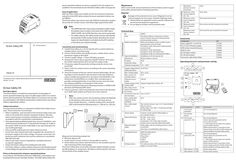
IQ box Safety
Area of application With the IQ box Safety and suitable sensors the maximum protection rating from the GEZE safety analysis for power-operated windows can be fulfilled. The IQ box Safety may only be used with GEZE IQ windowdrive window drives and non-contact sensors and safety edges approved by GEZE. Maintenance GEZE recommends annual maintenance of the window system to guarantee safety and permanent clamping protection. Disposal Damage to the environment can occur if disposal is not carried out properly. For this reason, heed the following notes: X Always follow the applicable country-specific disposal and environmental protection regulations. X Do not dispose of these with household waste. Note 193670-01 Translation of the original operating instructions for device version … / A0 IQ box Safety DR Brief description The IQ box Safety is a module for protecting the closing edges of power-operated windows by means of safety edges and/or non-contact sensors (pinch protection). The IQ box Safety is an accessory and can only be used together with GEZE IQ windowdrive window drives. One IQ box Safety is required per window. Safety instructions To ensure personal safety, it is important to follow these safety instructions. These instructions must be kept. à Before installation, read and observe the enclosed safety notes and notes on the protection of power-operated windows. Warranty claims require proper mounting, installation and maintenance in accordance with the manufacturer's specifications. à Only appropriately qualified people may carry out installation, commissioning and maintenance. If unauthorised changes are made to the system, GEZE cannot be made liable in any way whatsoever for any resulting damages. à Only use GEZE original parts for repair and service work. à Ensure that only a trained electrician completes the connection of the power supply to the mains voltage. The power connection and protective earth conductor test must be carried out in accordance DIN VDE 0100-600 à Observe the latest versions of guidelines, standards and country-specific regulations. à Protect the IQ box Safety from building dirt and water. à The IQ box Safety is a safety-related component and detailed specialist knowledge through product training is required to understand it. Notes on the protection of power-operated windows In accordance with Machinery Directive 2006/42/EC a risk analysis must be prepared for power-operated windows. The GEZE safety analysis for General information Connection and commissioning X Install IQ box Safety on a 35 mm top hat rail in a control cabinet or suitable surface-mounted casing. X Connect IQ box Safety and suitable sensors, window drives, activation/power supply as described. X Connect supply voltage -> Power LED lights up green. X Activate the sensor inputs required using DIP switches. (First, press the CLOSE window button (8) to activate the safety mode). X If necessary, adapt the parameter settings using the service case and ST220. X Teach-in the non-contact sensors according to the sensor operating instructions. X Check the function of the non-contact sensors/safety edges. All closing edges must be tested for safe operation under real conditions using a suitable testing element in accordance with EN 60335-2-103 (dimensions 25x100x300mm or smaller). Non-recorded areas or possible reaching behind the sensor field must be corrected using the setting possibilities or the position of the sensor. X Check the protection behaviour following activation in OPEN/CLOSE direction and following SHEV alarm. X Instruct customers, document protection (see note) in the risk analysis or GEZE safety analysis and hand over to the customer. Note: With non-contact sensors, the remaining residual risk depends on the distance of the sensor to the on-site limits (A) (e.g. frame, façade elements, ...) and the overlap of the risk area (B) GEZE recommends the following values: A < 300 mm, B > 500 mm. A 187677 One IQ box Safety is required per window. Up to … window drives and … locking drives can be used per window. Modes of operation SHEV and ventilation mode via SHEV control panel (polarity reversal mode) Ventilation mode with power supply (polarity reversal mode) Ventilation mode with IQ gear Ventilation mode with IQ box KNX Ventilation mode via control panel (F1200+) Type of installation Installation on 35 mm top hat rail Dimensions 90 mm x 60 mm x 35 mm IP rating IP 20 Protection rating III Ambient temperature -5°C…+70°C Supply voltage IQ box Safety and drives Max. residual ripple Max. current consumption drives Induced current intake Supply voltage of the sensors (24V) Max. total current load at 24V outputs for sensors Connection cross-section terminals Max. overall cable length for drives (LIN-BUS) Max. cable length sensors 18-30 V DC Sensor inputs … inputs, can be used for safety edges or non-contact sensors. GC 339+ (max. … pcs.) GC 342 (max. … pcs.) Combination with safety edges possible. Further sensors only after approval by GEZE Safety edges with terminating resistance of 4k5 to 22k Ohm max. … pcs. or combination with sensors. Sensor B B B Sensors EN Wiring diagram ID Note Approved sensors Approved safety edges B Compatible drives Measures for minimising residual risk: X Minimise distance (A). X Install a further sensor so that it is not possible to reach in. X IQ box Safety may only be used where the on-site conditions permit safe monitoring of the closing edges. The IQ box Safety does not provide protection against dangers caused by falling objects or components. No objects may be placed in the area of movement of the window leaves. Drives IQ box Safety DR Technical data Electrical data à The OPEN direction may not be protected in SHEV mode. If windows have to close in the event of an SHEV alarm (SHEV CLOSE), the CLOSE direction may not be protected. à For safety reasons, the safety mode must be activated by pressing the CLOSE window button (8) before the sensor inputs are deactivated or activated via the DIP switches or the drives are closed manually. Function (factory setting) power-operated windows can serve as a guide for the risk analysis. It is available in the download area for the IQ box Safety under www.geze.de. Software drives 20 U_ss [%] 10 A 100 mA Supply voltage IQ box Safety -6% Monitored direction of drive movement Behaviour when sensor triggered SI1 / SI3 Behaviour when sensor triggered SI2 / SI4 Behaviour when sensor released SI1 / SI3 Behaviour when sensor released SI2 / SI4 Close Drive stops Drive stops and reverses Drive carries out last movement command Drive waits for new movement command Accessories Designation Power supply NT … A-24 V HS NT … A-24 V HS power supply GEZE surface-mounted housing GEZE GC 339+ GC 342 (right module) GC 342 (left module) Connection cable IQ box Safety ID 151425 151424 152010 203858 167435 167432 193394 Operating elements and parameter setting … 4 … 5 … 8 … 11 121 132 10 … 1140 … 162 … 487 1980 … A … 3 … 6SI4 4L SI 24V … 7 … 13 … 5 4SI3 6A … 24V … 9 SYS … 4 SI … 1 … 10 … 8 … ON … 4 … max. … mm² 50 m … 2 … Non-contact sensors: max. 10 m - heed technical … data for sensors. Safety edges: max. 200 m - heed technical data … for safety edge. … 6 GEZE IQ windowdrives Slimchain 24 V Powerchain E 250 NT F1200 + Power lock The software status of the drives must be V3.2 or higher or V1.0 for F1200+. … 1 Pos. … Component4 … Connection activation … 2 Connection drives 3, … Connection sensor SI1 / SI3 … State … 8 4, … Connection sensor SI2 / SI4 … 7 … 8 … 9 812 … 3 … IQ box Safety … DR … 187672 PWR … 3 OUT S B DIP switches 1-4 ON DIP switches 1-4 OFF … 2 … 4 … 6 … 7 … 9 … 9 11 12 … 4 10 … 7 … 9 Explanation See wiring diagrams See wiring diagrams See wiring diagrams Sensor input pre-parameter set for non-contact sensors => deactivate sensor inputs not used by means of DIP switches. Before deactivation or activation of the sensor inputs, press the CLOSE window (8) button briefly to activate safety mode. See wiring diagrams Sensor input pre-parameter set for safety edges => deactivate sensor inputs not used by means of DIP switches. Before deactivation or activation of the sensor inputs, press the CLOSE window (8) button briefly to activate safety mode. Sensor input active Sensor input inactive … System LED … System LED … System LED on (red) 10 Power LED 10 Power LED on (green) off 10 Power LED 11 flashes (green) Service case and ST220 A B … S L … Sensor fault => Check sensor and sensor connection SI2 SI … 1 … 3 … 5 … 7 … 24V … 6 … 5 … 9 … 8 … RD BK WH … Internal error => Restart system (supply voltage OFF/ON), replace box. 24V TST A B … 4 S … + - + 24 V DC … SI1 GND SI L … 5 24V … SI2 SI … 4 … 6 … 8 N … 7 … 4 51 62 … 7 84 95 … 7 … 9 … 3 … 3 … 5 … 4 … 6 … 8 … 7 … 9 … 2 … PK … 24V … TST A PK … 3 … 5 … 4 … 6 … 8 … 7 … 9 … SI1 GND SI B … S … 1 TST … 5 24V L … SI2 … 3 … 5 … 7 … 9 GND SI GC 342 … Note: SI … 9 S … SHEV … control … panel GY … red black white … 6 BN 24V BN BU GN GY PK RD brown blue green grey pink red GC 339+ Note: X X GND SI GC 339+ RD BK … WH … PK … BU … 6 … BK … BU … RD … 5 Connection of sensors GC 342 or GC 339+ With mode of operation IQ box KNX, IQ gear, F1200+ Window GN … 4 Safety edge BU … 3 Note: X Connect safety edges to sensor inputs SI2 / SI4. X Note the permissible terminating resistors of the safety edges (see technical data). Heed the instructions for the safety edge. X The safety edges to be connected must be sized, mounted and put into operation independently, in accordance with the local circumstances and requirements of the Machinery Directive. RD … 2 … Connection window drives and activation … 1 … Connection safety edges TST GC 342 Sensors GC 342 and GC 339+ require a permanent 24 V supply. Therefore an additional 24 V power supply (e.g. power supply NT … A-24 V HS) is required in polarity reversal mode (SHEV control panel / power supply). X Connect sensors and 24 V power supply to sensor inputs SI1 / SI3. X Heed the instructions for the sensors. X X … Relay test has failed, failed initialisation process => Restart system (supply voltage OFF/ON), replace box. Sensor OK and sensor triggered; all sensor inputs deactivated. Ready for operation, power supply OK Communication to the drive OK Power supply not OK => Check power supply and connection to IQ box Safety. Power supply OK Communication to the drive not OK => Check connection of the drives to IQ box Safety. => Check software version of the drives on the type plate. SW version … or higher is required. Connection of the service case (e.g. using IQ box Safety connection cable) Connect output A,B,S,L of the service case to (1). For parameter setting see user manual ID 153523 - Parameter setting with service terminal ST220 and service case. 24V GY SI1 GND SI … BN TST … BU 24V … PK System LED IQ box Safety is in safety mode. … 24 V DC + - BK … System LED … 230 V AC 24 V power supply Connect sensor to sensor inputs SI1 / SI3. Heed the instructions for the sensors. BU … 1 230 V AC L1 N RD System LED … 5 … 7 … Connection of sensors GC 342 or GC 339+ With operating mode polarity reversal mode (SHEV control panel / power supply) GN … on (green) flashes slowly (green) 1s on/ 1s off flashes quickly (green) 100 ms on/ 100 ms off flashes slowly (red) 1s on/ 1s off flashes quickly (red) 100 ms on/ 100 ms off flashes (yellow) IQ box Safety DR IQ windowdrive window drive Optional branching box and further slave drives (with Syncro) orlocking drives IQ box KNX in flush-mounting or top hat rail casing IQ gear and power supply Power supply with polarity reversal F1200+ activation via control panel SHEV control panel; install line monitoring at the last window; S line for distinction alarm/ventilation BU System LED … 2 … PK … Button pressure activates safety mode for … seconds. Sensors can only be deactivated or activated via DIP switch in safety mode and the window drives can be closed e.g. in the event of sensor fault by pressing the CLOSE window push button again in dead man's operation. Sensor OK No sensor triggered Push button for overriding sensor signals is pressed, window closes. RD Window CLOSE push button PK 8
PDF | 570 KB
Slimchain 230 V AC
Slimchain 230 V AC DE Anschlussplan EN Wiring Diagram FR Plan de raccordement ES Esquema de conexiones PL Schemat połączeń RU Схема соединений =+ 㘴兎⦍ 182234-00 Slimchain 230 V AC Inhaltsverzeichnis … 2 Symbole und Darstellungsmittel … Bestimmungsgemäße Verwendung … Zielgruppe … Produktbeschreibung … 3 … Produkthaftung … Sicherheitshinweise … Weitere Sicherheitshinweise … Sicherheitsbewusstes Arbeiten und Benutzen … 5 … Montagehinweise … Leitungsverlegung und elektrischer Anschluss … Elektrischer Anschluss … Tausch der Anschlussleitung … 7 … 9 10 11 12 13 Prüfen der montierten Anlage … 10 Inbetriebnahme … 10 Parametrierung des Antriebs … 12 Betriebsarten … 12 Wartung … 13 Entsorgung der Fensteranlage … 13 Technische Daten … 14 Anhang: Anschlussbild Antrieb … A-I EG-Konformitäts- und Einbauerklärung … A-II DE … Slimchain 230 V AC … Symbole und Darstellungsmittel Symbole und Darstellungsmittel Warnhinweise In dieser Anleitung werden Warnhinweise verwendet, um Sie vor Sach- und Personenschäden zu warnen. X Lesen und beachten Sie diese Warnhinweise immer. X Befolgen Sie alle Maßnahmen, die mit dem Warnsymbol und Warnwort gekennzeichnet sind. Warnsymbol Warnwort GEFAHR Bedeutung Gefahren für Personen. Nichtbeachtung führt zu Tod oder schweren Verletzungen. Weitere Symbole und Darstellungsmittel Um die korrekte Bedienung zu verdeutlichen, sind wichtige Informationen und technische Hinweise besonders herausgestellt. Symbol Bedeutung bedeutet „Wichtiger Hinweis“ bedeutet „Zusätzliche Information“ X Symbol für eine Handlung: Hier müssen Sie etwas tun. X Halten Sie bei mehreren Handlungsschritten die Reihenfolge ein. … Bestimmungsgemäße Verwendung … Zielgruppe Dieses Dokument richtet sich an geschultes Fachpersonal und eingewiesene Betreiber von elektrischen Lüftungs-, Rauch- und Wärmeabzugsanlagen (RWA/NRA/NRWG) mit entsprechenden Kenntnissen der Betriebsarten und potentiellen Gefahren der Anlage. … Produktbeschreibung Der Slimchain 230 V AC ist ein Elektrokettenantrieb zum elektromotorischen Öffnen und Schließen von Fenstern im Fassaden- und Schrägfassadenbereich, geeignet für einwärts und auswärts öffnende Kipp-, Klapp- und Drehflügel; à zur täglichen Be- und Entlüftung à für den Einsatz als einzelner Antrieb (Solo-Antrieb) an einem Fenster. (die Mehrfachmontage von zwei oder mehreren einzel-Antrieben dieses Typs an einem Fenster ist nicht zulässig.) à Betriebsspannung 230 V AC à zur Verwendung in trockenen Räumen im Innenbereich DE … Produkthaftung … Slimchain 230 V AC Produkthaftung à Gemäß der im Produkthaftungsgesetz definierten Haftung des Herstellers für seine Produkte sind die hier und in den zugehörigen Montageanleitungen des Produkts enthaltenen Informationen (Produktinformationen und bestimmungsgemäße Verwendung, Fehlgebrauch, Produktleistung, Produktwartung, Informations- und Instruktionspflichten) zu beachten. Die Nichtbeachtung entbindet den Hersteller von seiner Haftungspflicht. à Nur Sachkundige, die von GEZE autorisiert sind, dürfen Montage, Funktionsprüfung und Wartung durchführen. Eigenmächtige Veränderungen an der Anlage schließen jede Haftung von GEZE für daraus resultierende Schäden aus. à Bei Kombination mit Fremdgeräten übernimmt GEZE keine Gewährleistung. Auch für Reparatur- und Wartungsaufgaben nur GEZE-Originalteile verwenden. … Sicherheitshinweise Für die Sicherheit von Personen ist es wichtig, diesen Sicherheitshinweisen Folge zu leisten. Diese Anweisungen sind aufzubewahren! Das Produkt ist nicht dafür bestimmt durch Personen, einschl. Kinder, mit eingeschränkten physischen, sensorischen oder geistigen Fähigkeiten oder mangels Erfahrung und/oder mangels Wissen benutzt zu werden, es sei denn, sie werden durch eine für ihre Sicherheit zuständige Person beaufsichtigt oder erhielten von ihr Anweisungen wie das Produkt zu benutzen ist. Kinder nicht mit fest montierten Regel- und/oder Steuereinrichtungen spielen lassen und Fernsteuerungen außerhalb der Reichweite von Kindern halten. Personen, einschl. Kinder, sind fernzuhalten, wenn ein Schalter mit AusVor- einstellung betätigt wird oder wenn sich ein Fensterflügel schließt, das durch ein Rauch- und Wärmeabzugssystem geöffnet wurde. … Weitere Sicherheitshinweise Vor Inbetriebnahme der Anlage ist eine Risikobeurteilung gemäß der Maschinenrichtlinie 2006/42/EG durchzuführen (z. B. auf Basis der GEZE Sicherheitsanalyse für kraftbetätigte Fenster) und die Anlage gemäß Anhang III der EG-Maschinenrichtlinie mit der CE-Kennzeichnung zu versehen. Der neueste Stand von Richtlinien, Normen und länderspezifischen Vorschriften ist zu beachten, insbesondere: à DGUV Vorschrift … „Unfallverhütungsvorschrift, Grundsätze der Prävention“. à DGUV Vorschrift … „Unfallverhütungsvorschrift, elektrische Anlagen und Betriebsmittel“. à ASR A1.6 „Fenster, Oberlichter, lichtdurchlässige Wände“. DE … Slimchain 230 V AC Sicherheitshinweise à VDE 0100, Teil 600 „Errichten von Niederspannungsanlagen Teil 6. Prüfungen“. à DIN EN 60335-1 „Sicherheit elektrischer Geräte für den Hausgebrauch und ähnliche Zwecke - Teil 1: Allgemeine Anforderungen“. à DIN EN 60335-2-103 „Sicherheit elektrischer Geräte für den Hausgebrauch und ähnliche Zwecke - Teil 2-103: Besondere Anforderungen für Antriebe für Tore, Türen und Fenster. à MLAR „Muster-Leitungsanlagen-Richtlinie“. à Wenn die Anschlussleitung dieses Gerätes getauscht werden muss, darf dies nur durch eine Elektrofachkraft durchgeführt werden. GEFAHR Verletzungsgefahr durch Auf- oder Zuschlagen des Fensterflügels: Die e Antriebskette darf im geöff geöffneten neten Zustand des Fensters nicht abgekoppelt werden. Bei Demontage der Verbindung Antrieb/Fenster ist der Fensterflügel fachgerecht gegen ein Auf- oder Zuschlagen abzusichern. Das Produkt sollte so eingebaut oder verbaut werden, dass ein müheloser Zugriff auf das Produkt bei etwaigen Reparaturen und/oder Wartungen mit verhältnismäßig geringem Aufwand gewährleistet ist und etwaige Ausbaukosten nicht in einem Missverhältnis zu dem Wert des Produktes stehen. … Sicherheitsbewusstes Arbeiten und Benutzen X X X X à à à à Arbeitsplatz gegen unbefugtes Betreten sichern. Schwenkbereich langer Anlagenteile beachten. Vor Arbeiten an elektrischen Anlagen die Spannungszufuhr unterbrechen, gegen Wiedereinschalten sichern und auf Spannungsfreiheit prüfen. Bei Verwendung einer unterbrechungsfreien Stromversorgung (USV) ist die Anlage auch bei netzseitiger Freischaltung unter Spannung Antriebe beim Einrichten nur im Tastbetrieb ansteuern. Verletzungsgefahr bei geöffnetem Antrieb durch bewegte Teile (Einziehen von Haaren, Kleidungsstücken usw.) Verletzungsgefahr durch nicht gesicherte Quetsch-, Stoß-, Scher- und Einzugsstellen. Verletzungsgefahr durch Glasbruch. Anfassen der Fensteranlage während des Betriebs kann zu Verletzungen führen. DE … Montagehinweise … Slimchain 230 V AC Montagehinweise GEFAHR Wichtige Anweisungen für die sichere Montage. Falsche Montage kann zu ernsthaften Verletzungen führen. Alle Anweisungen beachten. Der Antrieb ist dazu bestimmt an Fenstern in einer Höhe von ≥ 2,5 m über der Zugangsebene montiert zu werden. Nach den in Kap. … genannten Normen/Regeln muss die Schließgeschwindigkeit unter … mm/Sek. liegen, wenn keine weiteren Sicherungsmaßnahmen am Fenster selbst getroffen werden bzw. wenn das Fenster unter 2,5 m Höhe eingebaut ist (siehe hierzu S.6 ASR A1.6). GEZE Antriebe sind werksseitig auf diese Geschwindigkeit eingestellt. à Bei Einbauhöhen unter 2,5 m über Zugangsebene: à ist ein Schalter mit Aus-Voreinstellung (Taster) zu verwenden. Das Betätigungselement von Schaltern mit Aus-Voreinstellung muss in direkter Sichtweite vom Fenster, aber entfernt von sich bewegenden Teilen angebracht sein; falls es kein Schlüsselschalter ist, muss es in einer Höhe von mindestens 1,5 m und unzugänglich für die Öffentlichkeit angebracht sein. à Gemäß EN60335-2-103 Abschn. … darf bei Einbauhöhen unter 2,5 m über Zugangsebene nur der Hub von 200 mm eingestellt werden. à Der Antrieb ist ausschließlich für den Einsatz in trockenen Räumen bestimmt und darf keiner stark korrosionsgefährdenden Umgebung ausgesetzt werden (z.B. Meeres- oder Seeluft). X Lesen und beachten Sie die Angaben in der Montageanleitung und bewahren Sie diese für den späteren Gebrauch auf. Alle Maßangaben sind am Bau eigenverantwortlich zu prüfen. X Prüfen, ob die auf dem Typenschild des Antriebes angegebenen Bedingungen wie Umgebungstemperatur und elektrische Daten am vorgesehenen Einbauort eingehalten werden. X Vor dem Einbau prüfen, ob das angetriebene Teil in einem guten mechanischen Zustand ist, gewichtsmäßig ausgeglichen ist und sich leicht schließen lässt. X Um Verletzungen zu vermeiden, sind Schutzkappen auf überstehende Gewinde der Befestigungsschrauben zu setzen. X Sicherstellen, dass ein Einschließen zwischen dem Fensterflügel und den umgebenden festen Teilen aufgrund der Öffnungsbewegung des Fensterflügels verhindert wird. DE … Slimchain 230 V AC Montagehinweise GEFAHR Verletzungsgefahr durch Auf- oder Zuschlagen des Fensterflügels: Bei Kippfenstern zusätzlich zu beachten: X X X GEZE-Sicherheitsscheren (Typ 35 oder Typ 60) verwenden. Fehlen die Sicherheitsscheren, darf das Kippfenster nicht betrieben werden. Für die Montage der Scheren sind die GEZE Verarbeitungs- und Montagerichtlinien einzuhalten Achtung: Quetsch- und Klemmgefahr - Sicherstellen, dass ein Einschließen im Bereich der Sicherheitsscheren verhindert wird. Bei Montage beachten: à Zur Befestigung dürfen nur Original-Konsolen verwendet werden. à Zur Montage geeignete Befestigungselemente benutzen. Empfehlungen finden sich in den jeweiligen Montageanleitungen. Sicherstellen, dass die Befestigungselemente im Profil für einen sicheren Halt der montierten Teile sorgen. Bei Verwendung von Antrieben zur Betätigung von Kippfenstern (Öffnen/ Schließen) besteht die potentielle Gefahr des Herabstürzens der Fensterflügel. Daher schreibt GEZE zwingend die Verwendung von separaten nicht mit dem Antrieb verbundenen „GEZE-Sicherheitsscheren“ vor. Die GEZE-Sicherheitsscheren sorgen dafür, dass eine dauerhaft feste Verbindung von Rahmen und Flügel – unabhängig vom Antrieb – gewährleistet ist. Nur bei Verwendung der GEZE-Sicherheitsscheren (Typ 35 oder Typ 60) ist das angetriebene Kippfenster sicher gegenüber Abstürzen. Herabstürzende Fensterflügel können eine erhebliche Gefahr für Leib und Leben von Personen, die sich im Umkreis befinden, darstellen. Daher ist im Einsatz von GEZE Antrieben an Kippfenstern die Verwendung von GEZESicherheitsscheren zwingend vorgeschrieben. DE … Leitungsverlegung und elektrischer Anschluss … Leitungsverlegung und elektrischer Anschluss X X X X X X X … Slimchain 230 V AC Sicherstellen dass der Anschluss an die Netzspannung nur von einer Elektrofachkraft durchgeführt wird. Netzanschluss muss entsprechend DIN VDE 0100-600 durchgeführt werden. Als netzseitige Trennvorrichtung einen bauseitigen, 2-poligen Sicherungsautomaten mit Verriegelungsmöglichkeit, entsprechend der zulässigen Strombelastbarkeit des Kabels, verwenden. Bei den Anschlüssen von Komponenten müssen die Angaben in dieser Beschreibung beachtet werden. Die Planung und Berechnung des Leistungsnetzes obliegt dem sachkundigen Errichter und muss entsprechend der gesetzlichen Vorschriften durchgeführt werden (in Deutschland z. B. nach der MLAR). Vor der Freigabe der Anlage für den Betrieb eine lsolationsmessung des Leitungsnetzes der Anlage durchführen und protokollieren Nur die im Anschlussplan angegebenen Kabel verwenden. Kabelart, Leitungslänge und -querschnitt gemäß den technischen Angaben ausführen. Für Litzenkabel grundsätzlich Aderendhülsen verwenden. Nicht benutzte Adern isolieren. Elektrischer Anschluss GEFAHR Vor Arbeiten an der elektrischen Anlage die Spannungszufuhr unterbrechen, gegen Wiedereinschalten sichern und auf Spannungsfreiheit prüfen. … BU blau N BN braun ZU (230 V AC) BK schwarz AUF (230 V AC) Tausch der Anschlussleitung Falls erforderlich (z. B. andere Leitungslänge, Defekt) kann die mitgelieferte Anschlussleitung (2 m) ausgetauscht werden: à Der Austausch ist nur durch eine Elektrofachkraft zulässig. Es darf nur der gleiche Kabeltyp mit einem Temperaturbereich -5°C .... 80°C, z. B. GEZE Mat. Nr. 183191 verwendet werden. DE … Slimchain 230 V AC Leitungsverlegung und elektrischer Anschluss 1. Deckel für Netzanschluss am Antrieb öffnen und Zugentlastung lösen. 2. Kabel mit Stecker senkrecht abstecken. Torx® TX10 PZ1 3. Kabel vom Stecker abklemmen und neue Anschlussleitung anklemmen, dabei Aderendhülsen verwenden. BK BN BU A Z 4. Stecker mit neuem Kabel einstecken und Zugentlastung montieren. N 5. Deckel montieren und verschrauben. Anzugsmomente Schrauben: à Deckel für Netzanschluss: Torx ®T10, 0,7-0,9 Nm à Zugentlastung: Kreuzschlitz PZ1, 0,9-1,1 Nm DE … Prüfen der montierten Anlage … Slimchain 230 V AC Prüfen der montierten Anlage à Maßnahmen zur Absicherung bzw. Vermeidung von Quetsch-, Stoß, Scherund Einzugsstellen sind insbesondere bei Gefahrenstellen von unter 2,5 m zu prüfen und durchzuführen. Eine Maßnahme ist z. B. die Verwendung eines Schalters mit Aus-Voreinstellung (z. B. GEZE Lüftertaster LTA-LSA GEZE Mat. Nr. 118476). Bei Kindern oder Personen mit eingeschränktem Urteilsvermögen muss ein Schlüsselschalter mit Aus-Voreinstellung verwendet werden (z. B. GEZE Mat. Nr. 117996 für SCT, GEZE Mat. Nr. 090176 für Zylinder). Die Schalter müssen so angebracht sein, dass die Gefahrenstellen eingesehen werden können. X Nach der Installation ist zu überprüfen, dass die Anlage richtig eingestellt ist und richtig und gefahrlos funktioniert. X Alle Funktionen durch Probelauf überprüfen. X Der Endanwender muss nach der Fertigstellung in allen wichtigen Bedienschritten eingewiesen werden. X Zur Information des Elektrikers diesen Anschlussplan aushändigen. X Reinigungspersonal muss zu einer sicheren Nutzung der Anlage vom Gebäudebetreiber eingewiesen und entsprechend auf die Gefahren der kraftbetätigten Fenster hingewiesen werden. à Fenster darf nur im geschlossenen Zustand von außen bzw. von innen gereinigt werden. X Der Antrieb ist vor Bauschmutz und Strahlwasser zu schützen. … Inbetriebnahme Der Antrieb kann beim ersten Anlegen der Betriebsspannung sowohl in „AUF“-Richtung als auch in „ZU“-Richtung betrieben werden. Der Antrieb erkennt die Schließposition des Fensters beim ersten Schließen automatisch und speichert diese ab. Es ist zu beachten, dass dabei keine Behinderung besteht. Sollte der Antrieb beim Erreichen der Schließlage reversieren (Antrieb öffnet um ca. 15 mm) muss eine Inbetriebnahmefahrt gestartet werden, gehen Sie dazu wie folgt vor: X Servicedeckel am Antriebsgehäuse öffnen. X Taster S1 unter dem Servicedeckel für ca. … Sek. betätigen (Fenster beginnt zu schließen). X Nach der Inbetriebnahmefahrt Servicedeckel wieder schließen (Anzugsmoment max. 0,9 Nm). DE 10 Slimchain 230 V AC Inbetriebnahme Taster S1 wird nur bei anliegender Spannung und Stillstand des Fensters abgefragt. Servicedeckel Torx® TX15 Taster S1 Wenn aufgrund der Einbausituation der Servicedeckel nicht oder nur schwer zugänglich ist, kann alternativ die Inbetriebnahmefahrt auch über den eingebauten Reedkontakt und einen Magnet (ca. Ø8 x 20 mm) gestartet werden: Dazu Magnet gemäß Skizze für ca. … Sek. an den Antrieb halten. DE 11 Parametrierung des Antriebs … Slimchain 230 V AC Parametrierung des Antriebs Der Antrieb kann mit Hilfe des LIN-Parametrieradapters (GEZE Mat. Nr. 179238) und des Parametriergeräts ST 220 (GEZE Mat. Nr. 087261) parametriert werden. Dazu: X Servicedeckel öffnen und Parametrieradapter einstecken X Antrieb an 230 V anschließen und in „ZU“-Richtung betreiben X Warten bis der Antrieb die Endlage „ZU“ erreicht hat‘ X Parametrierung mittels ST 220 durchführen GN BN FSE 301 LINKabel LIN +24 V WH GND L ST 220 B A LIN-Parametrieradapter ST 220 Verbindungskabel Stiftleiste zum Aufstecken des LIN-Parametrieradapters GN grün/green BN braun/brown WH weiß/white Der mögliche Überschlagbereich für die Antriebe liegt bei 8-23 mm. Bei Fenstern mit einem Überschlag >23 mm muss der Hub des Antriebs reduziert werden. Weitere Information zur Parametrierung finden Sie in der Anleitung GEZE Mat. Nr. 153523 zum Parametriergerät. 10 Betriebsarten Betriebsart Lüftung Antrieb öffnet mit Lüftungsgeschwindigkeit bis zum Lüftungshub DE 12 Slimchain 230 V AC Wartung X Bitte beachten Sie hierzu den zugehörigen Anschlussplan im Anhang A-I dieses Dokuments. Der Lüftungshub ist auf max. Hublänge eingestellt. Mit Hilfe des Parametriergeräts ST 220 kann der Lüftungshub parametriert werden. 11 Wartung GEZE schreibt eine regelmäßige Wartung (mindestens 1x jährlich) vor. Diese ist von einem Sachkundigen auszuführen. Dabei müssen die Funktion sowie der Zustand der Mechanik (Ungleichgewicht oder Anzeichen von Verschleiß, Beschädigung von Befestigungsteilen) und der elektrischen Anschlüsse überprüft werden. Während der Reparatur- und Einstellarbeiten darf die Anlage nicht benutzt werden. X Vor Beginn der Wartungsarbeiten die Spannungszufuhr (Netz 230 V AC) unterbrechen, gegen Wiedereinschalten sichern und auf Spannungsfreiheit prüfen. X Befestigungen und Klemmschrauben auf festen Sitz prüfen. X Bei Wartung den Antrieb von Verunreinigungen befreien. GEFAHR Quetsch- und Klemmgefahr! Das Fenster schließt automatisch! Vor Montage beiliegende Sicherheitshinweise lesen und bei Montage und Betrieb des Antriebs beachten! Gewährleistungsansprüche setzen eine fachgerechte Montage, Installation und Wartung nach den Angaben des Herstellers voraus. 12 Entsorgung der Fensteranlage Die Fensteranlage besteht aus Materialen, die der Wiederverwertung zugeführt werden sollten. Dazu sind die Einzelkomponenten entsprechend ihrer Materialart zu sortieren: à Aluminium (Profile, ...) à Eisen (Schrauben, Kette, ...) à Kunststoffe à Elektronikteile (Motor, Steuerung, Transformator, Relais, ...) à Kabel X Die Teile entsprechend den gesetzlichen Bestimmungen entsorgen. DE 13 Technische Daten 13 Slimchain 230 V AC Technische Daten Slimchain 230 V Mechanische Daten Zugkraft [N] 300 Druckkraft [N] 200 Hublänge [mm] (siehe Typenschild Antrieb) 200 - 800 Standard Lüftungshub * parametrierbar = Hublänge* Hubgeschwindigkeit [mm/sek.] * parametrierbar (3 -7 mm/sek) Öffnen : 5* Schließen: 5* Endlagenabschaltung ausgefahren elektronisch über internen Weggeber Endlagenabschaltung eingefahren elektronisch über Weg und Last Überlastabschaltung elektronisch über Stromaufnahme Gewicht [kg] 1,1 - 1,7 Hub / Länge Antrieb [mm] 200 / 478 300 / 528 500 / 628 800 / 778 Elektrische Daten Spannung [V AC] DE 14 230 +/-10% Frequenz [Hz] 47-63 Einschaltdauer [%] 30 Kurzzeitbetrieb [min] … Leistungsaufnahme [W] 30 Stromaufnahme Lüftungsbetrieb [A] 0,3 Parallelschaltung Antriebe max. Umgebungstemperatur [°C] 10 -5 / +70 Schutzart [IP] / Schutzklasse IP 30 / II Anwendungsbereich trockene Räume Anschlusskabel/-querschnitt [mm²] … x 0,75, PVC, 80°C Länge Anschlusskabel [m] 2, optional Sonderlänge Technische Daten Slimchain 230 V AC Contents … 2 Symbols and illustrations … Intended use … Target group … Product description … 3 … Product liability … Safety notices … Further safety notices … Safety-conscious working and usage … 5 … Installation details … Routing cables and electrical connection … Electrical connection … Replacing the connection cable … 7 … 9 10 11 12 13 Inspection of installed system … 10 Commissioning … 10 Setting the parameters of the drive … 12 Operating modes … 12 Maintenance … 13 Disposal of the window unit … 13 Technical data … 14 Appendix: Drive wiring diagram … A-I EC Declaration of Conformity and Incorporation … A-II EN … Slimchain 230 V AC … Symbols and illustrations Symbols and illustrations Warning notices Warning notices are used in these instructions to warn you of property damage and personal injury. X Always read and observe these warning notices. X Observe all measures marked with the warning symbol and warning word. Warning symbol Warning word Meaning Danger to persons. DANGER Non-compliance will result in death or serious injuries. Further symbols and illustrations Important information and technical notes are highlighted to explain correct operation. Symbol Meaning means “important note” means “additional Information” X Symbol for an action: This means you have to do something. X If there are several actions to be taken, keep to the given order. … Intended use … Target group This document addresses trained specialists and instructed operators or electrically operated ventilation, smoke and heat extraction systems (RWA/ NRA/NRWG) with corresponding knowledge of the modes of operation and potential hazards of the system. … Product description The Slimchain 230 V AC is an electrical chain drive for the electro-motive opening and closing of windows in straight and slanted façades, suitable for inwardopening and outward-opening bottom-hung, top-hung and side-hung leaves; à for daily ventilation à for use as an individual drive (solo drive) at one window. (Multiple installation of two or more individual drives of this type on one window is not permitted.) à operating voltage 230 V AC à for use in dry rooms on the interior EN … Product liability … Slimchain 230 V AC Product liability à In accordance with the liability of the manufacturer for his products as defined in the German “Produkthaftungsgesetz” (Product Liability Act), the information contained in this brochure and in the corresponding installation instructions of the product (product information and proper use, misuse, product performance, product maintenance, obligations to provide information and instructions) is to be observed. Failure to comply with this information releases the manufacturer from its statutory liability. à Only qualified personnel who are authorised by GEZE may carry out mounting, function check and maintenance. GEZE shall not be liable for injuries or damage resulting from unauthorised modification of the equipment. à GEZE makes no guarantee for combinations with third-party devices. Use only original GEZE parts for repair and maintenance work as well. … Safety notices To ensure personal safety, it is important to follow these safety instructions. These instructions must be kept. The product has not been designed to be used by people, including children, who have restricted physical, sensory or mental abilities or a lack of experience and/or knowledge, unless they are supervised by a person responsible for their safety or have received instructions from that person as to how the product is to be used. Do not allow children to play with permanently installed control systems of any kind and keep remote controls out of reach of children. People, including children, must be kept out of the way when a switch with an OFF default setting is activated or when a leaf that has been opened by a smoke and heat extraction system closes. … Further safety notices Before commissioning of the system, a risk assessment must be carried out in compliance with the Machinery Directive 2006/42/EC (e.g. on the basis of the GEZE safety analysis for power-operated windows) and the system must be given the CE marking in compliance with Annex III of the EC Machinery Directive. Observe the latest status of directives, standards and country-specific regulations, in particular: à DGUV regulation … “Accident prevention regulations, principles of prevention”. à DGUV regulation … “Accident prevention regulations, electrical installations and equipment”. à ASR A1.6 “Windows, fanlights, translucent walls”. EN … Slimchain 230 V AC Safety notices à VDE 0100, Part 600 “Erection of low-voltage systems Part 6. Tests”. à DIN EN 60335-1 “Safety of electrical devices for home use and similar purposes - Part 1: General requirements”. à DIN EN 60335-2-103 “Safety of electrical devices for home use and similar purposes - Part 2-103: Special requirements for drives for gates, doors and windows.” à MLAR “Model Conduit Systems Directive”. à If the connection cable of this device has to be replaced, this work may only be carried out by a qualified electrician. DANGER Risk of injury by the window leaf slamming open or closed: The drive chain must not be decoupled when the window is opened. When the drive/window connection is dismantled, the window leaf must be secured properly against slamming open or closed. The product should be installed or incorporated in such a way that effortless access to the product is guaranteed during any repairs and/or maintenance, and that any removal costs do not stand out of proportion to the value of the product. … Safety-conscious working and usage X X X X à à à à Secure workplace against unauthorised entry. Watch the swivelling range of long system parts. Before working on the electrical system interrupt the power supply, secure it against being switched on again and verify the safe isolation from supply. Note that if an Uninterruptible Power Supply (UPS) is used, the system will still be supplied with voltage despite the fact that the power supply is disconnected During the set-up activate the drives only in inching mode. Risk of injury when a drive is opened through moving parts (drawing in of hair, clothing, etc.) Risk of injury by trapping, knocking, shearing and hair etc. being pulled in at unsecured points. Risk of injury due to broken glass. Touching the window unit can result in injuries during operation. EN … Installation details … Slimchain 230 V AC Installation details DANGER Important instructions for safe installation. Incorrect installation can result in serious injuries. Observe all the instructions. The drive has been designed for installation on windows at a height of ≥ … m above the access level. According to the standards/regulations mentioned in Chapter … , the closing speed must be less than … mm/sec if no further safety measures are taken on the window itself or if the window is installed at a height of less than … m (see p.6 ASR A1.6). GEZE drives have been adjusted to this speed in the factory. à For installation heights less than … m above the access level: à a switch with an OFF default setting (push button) must be used). The activation element of switches with an OFF default setting must attached in direct view of the window, but away from moving parts; if it is not a key-operated switch it must be attached at a height of at least … m and be inaccessible to the general public. à In compliance with EN60335-2-103 section … , only the 200 mm stroke may be set for installation heights less than … m. à The drive is designed solely for use in dry rooms and may not be subjected to highly corrosive environments (e.g. sea air or marine air). X Read and observe the specifications in the installation instructions and keep these for later use. All the dimensions specified have to be checked on site on own initiative and responsibility. X Check whether the conditions specified on the information plate of the drive such as the ambient temperature and electrical data are observed at the planned installation site. X Before installing the driven part check whether it is in a good mechanical state, has a balanced weight and can be closed easily. X in order to avoid injuries, protective caps are to be placed onto projecting threads of the fastening screws. X Make sure that enclosing between the window leaf and the surrounding fixed parts due to the opening movement of the window leaf is prevented. EN … Slimchain 230 V AC Installation details DANGER Risk of injury by the window leaf slamming open or closed: The following must be heeded in addition in the case of bottom-hung windows: X X X Use GEZE safety scissors (type 35 or type 60). The bottom-hung window must not be operated if the safety scissors are missing. The GEZE processing and installation guidelines must be observed during installation of the scissors. Note: Danger of pinching and clamping - make sure that nothing can become caught in the area of the safety scissors. During installation, heed the following: à Only genuine consoles may be used for attachment. à Use suitable fixing elements for installation. Recommendations can be found in the respective installation instructions. Make sure that the fixing elements in the profile fix the installed parts in place securely. When drives are used for activating bottom-hung windows (open/close), there is a potential danger of the window leaves falling out. For this reason, GEZE prescribes the compulsory use of separate GEZE safety scissors not connected with the drive. The GEZE safety scissors ensure that a permanent fixed connection between the frame and leaf is guaranteed – independently of the drive. The driven bottom-hung window is only safely protected against falling out when GEZE safety scissors (type 35 or type 60) are used. Falling window leaves can be a significant danger for the life and limb or persons near the window. For this reason, the use of GEZE safety scissors is compulsory when GEZE drives are used on bottom-hung windows. EN … Routing cables and electrical connection … Routing cables and electrical connection X X X X X X X … Slimchain 230 V AC Ensure that the connection to the power supply is only carried out by a qualified electrician. The main connection must be carried out according to DIN VDE 0100-600. Use an on-site, 2-pole automatic circuit breaker with locking option, according to the permissible current carrying capacity of the cable, as the disconnecting device on the mains side. The details in these instructions must be observed when connecting components. Planning and calculation of the power network is to be done by a qualified installer and has to be carried out in accordance with the statutory regulations (in Germany for example in accordance with MLAR). Before the system is approved for operation, carry out and log an isolation measurement of the supply network of the system Use only cables prescribed in the wiring diagram. Implement the cable type, line length and cross-section in accordance with the technical specifications. Always use wire-end ferrules for wire cores. Insulate wires that are not used. Electrical connection DANGER Before working on the electrical system interrupt the power supply, secure it against being switched on again and verify the safe isolation from supply. … BU blue N BN brown CLOSE (230 V AC) BK black OPEN (230 V AC) Replacing the connection cable The connection cable provided (2 m) can be replaced if necessary (e.g. different cable length, faulty): à Replacement is only permissible when carried out by a qualified electrician. Only the same cable type with a temperature range of -5°C .... 80°C, e.g. GEZE mat. no. 183191 may be used. EN … Slimchain 230 V AC Routing cables and electrical connection 1. Open the cover for the mains connection on the drive and loosen the strain relief. 2. Unplug the cable with connector vertically. Torx® TX10 PZ1 3. Disconnect the cable from the connector and connect the new connection cable using wire end ferrules. BK BN BU A Z 4. Plug in the connector with new cable and fit the strain relief. N 5. Fit the cover and screw in place. Screw tightening torques: à Cover for mains connection: Torx ®T10, … - … Nm à Strain relief: Cross slot PZ1, … - … Nm EN … Inspection of installed system … Slimchain 230 V AC Inspection of installed system à The measures for protection and prevention of crushing, impact, shearing or drawing-in spots, in particular at points with a height of less than … m are to be considered and carried out. One measure is, for example, to use a switch with an OFF default setting (for example GEZE vent switch LTA-LSA GEZE mat. no. 118476). In the case of children or persons with a limited ability to judge, a keyoperated switch with an OFF default setting has to be used (for example GEZE mat. no. 117996 for SCT, GEZE mat. no. 090176 for cylinder). The switches must be mounted in such a way that the danger zones can be seen. X After installation has been completed, check that the system is set correctly and is functioning correctly and safely. X Check all the functions by carrying out a trial run. X The end user has to be instructed in all the important operating and handling steps after completion. X Inform the electrician by handing out this wiring diagram. X Cleaning staff must be instructed by the building operator on safe use of the system and be made aware of the dangers of power-operated windows. à Windows may only be cleaned from the outside or inside when they are closed. X The drive must be protected from construction dirt and splashwater. … Commissioning The first time operating voltage is applied, the drive can be operated in the “OPEN” and in the “CLOSE” direction. The drive automatically detects the closing position of the window when closing for the first time and saves this. It must be ensured that there is no hindrance at that time. Should the drive reverse after reaching the closing position (drive opens by approximately 15 mm), a commissioning run must be started. To do this, proceed as follows: X Open the service cover on the drive housing. X Activate push button S1 under the service cover for approx. … seconds (window starts to close). X Following the commissioning run, close the service cover again (tightening torque max. … Nm). Push button S1 is only queried with voltage applied and the window at a standstill. EN 10 Slimchain 230 V AC Service cover Commissioning Torx® TX15 Push button S1 If the service cover is not accessible or only with difficulty due to the installation situation, the commissioning run can be started via the built-in reedcontact and a magnet (approx. Ø8 x 20 mm): To do this, hold the magnet to the drive as shown in the sketch for approx. … seconds. EN 11 Setting the parameters of the drive … Slimchain 230 V AC Setting the parameters of the drive Parameters can be set for the drive using the LIN parameter setting adapter (GEZE mat. no. 179238) and the parameter setting device ST 220 (GEZE mat. no. 087261). To do this: X Open the service cover and insert the parameter setting adapter X Connect the drive to 230 V and operate in the “CLOSE” direction X Wait until the drive has reached the “CLOSE” end position X Carry out parameter setting using ST 220 GN BN FSE 301 LIN cable LIN +24 V WH GND L ST 220 B A LIN parameter setting adapter ST 220 Connection cable Pin strip for connecting the LIN parameter setting adapter GN green BN brown WH white The possible projection range for the drives is 8-23 mm. In the case of windows with a projection > 23 mm the drive stroke must be reduced. Further information about parameter setting can be found in the instructions GEZE mat. no. 153523 for the parameter setting device. 10 Operating modes Operating mode ventilation Drive opens at ventilation speed up to ventilation stroke EN 12 Slimchain 230 V AC Maintenance X Please note the corresponding wiring diagram in Annex A-I of this document. The ventilation stroke is set to max. stroke length. Parameters can be set for the ventilation strokewith the aid of the parameter setting device ST 220. 11 Maintenance GEZE prescribes regular maintenance (at least once a year). This is to be carried out by a suitably qualified person. In the process the function as well as the state of the mechanical equipment (imbalance or signs of wear, damage to fastening parts) and the electrical connections are to be checked. The system may not be used during repair and setting work. X Before starting maintenance work, interrupt the power supply (mains 230 V AC), secure against being switched on again and verify the safe isolation from supply. X Inspect the fixations and clamping screws for firm seating. X Clean soiling from the drive during maintenance. DANGER Danger of pinching and clamping! The window closes automatically!! Before installation, read the enclosed safety notes and consider them during installation and operation of the drive! Warranty claims require proper mounting, installation and maintenance in accordance with the manufacturer's specifications. 12 Disposal of the window unit The window unit consists of materials that have to be recycled. For this purpose, the individual components must be sorted according to material type: à Aluminium (profiles, ...) à Iron (screws, chain, ...) à Plastics à Electronic components (motor, control, transformer, relay, ...) à Cables X Dispose of the parts in accordance with the statutory regulations. EN 13 Technical data 13 Slimchain 230 V AC Technical data Slimchain 230 V Mechanical data Pulling force [N] 300 Compressive force [N] 200 Stroke length [mm] (see drive identification plate) 200 - 800 Standard ventilation stroke * parameters can be set = stroke length* Stroke speed [mm/sec] * parameters can be set (3 -7 mm/sec) Open: 5* Close: 5* End position cut-off extended electronic via internal path sensor End position cut-off retracted electronic via path and load Overload cut-off electronic via current consumption Weight [kg] … - … Stroke / drive length [mm] 200/478 300/528 500/628 800/778 Electrical data Voltage [V AC] 230 +/-10% Frequency [Hz] 47-63 Duty rating [%] 30 Short-term operation [min] … Power consumption [W] 30 Current consumption ventilation mode [A] … EN 14 Parallel connection drives max. Ambient temperature [°C] 10 -5 / +70 IP rating [IP] / protection type IP 30 / II Area of application dry rooms Connection cable/cross-section [mm²] … x … , PVC, 80°C Length of power supply cable [m] 2, optional special length Slimchain 230 V AC Sommaire … 2 Symboles et moyens de représentation … Utilisation conforme aux dispositions … Groupe cible … Description du produit … 3 … Responsabilité du fabricant du fait de son produit … Consignes de sécurité générales … Autres prescriptions de sécurité … Travail et utilisation respectueux des consignes de sécurité … 5 … Consignes de montage … Pose des lignes et raccordement électrique … Raccordement électrique … Remplacement du câble de raccordement … 7 … 9 10 11 12 13 Contrôle de l‘installation montée … 10 Mise en service … 10 Paramétrage de l’entraînement … 12 Modes de fonctionnement … 12 Entretien … 13 Mise au rebut de l‘installation de fenêtre … 13 Données techniques … 14 Annexe : Schéma de raccordement de l’entraînement … A-I Déclaration de conformité et d‘incorporation CE … A-II FR … Slimchain 230 V AC … Symboles et moyens de représentation Symboles et moyens de représentation Avertissements Dans ces instructions, des avertissements sont utilisés pour vous prévenir d’éventuels dommages corporels et matériels. X Lisez et respectez toujours ces avertissements. X Appliquez toutes les mesures indiquées par le symbole et le message d‘avertissement. Symbole Message Signification d’avertissement d’avertissement Danger pour les personnes. DANGER Un non-respect provoque des blessures graves, voire mortelles. Autres symboles et moyens de représentation Afin de garantir une utilisation conforme, les informations importantes et les indications techniques sont mises en valeur. Symbole Signification signifie « Indication importante » signifie « Informations complémentaires » X Symbole d'action : Dans ce cas, vous devez effectuer une action. X Veuillez respecter l’ordre des étapes d’intervention décrites. … Utilisation conforme aux dispositions … Groupe cible Ce document est destiné au personnel qualifié et formé et aux exploitants qualifiés des systèmes de ventilation, d’extraction de fumée et de la chaleur électriques (RWA/NRA/NRWG) avec les connaissances correspondantes des modes de fonctionnement et des dangers potentiels de l’installation. … Description du produit Le Slimchain 230 V AC est un entraînement à chaîne pour l’ouverture et la fermeture à moteur électrique de fenêtres dans les façades et les façades en biais, qui convient pour les fenêtres à soufflet, rabattables et à la française à ouverture vers l’intérieur et vers l’extérieur ; à Pour la ventilation et l’aération quotidiennes ; à Pour une utilisation comme entraînement individuel (entraînement Solo) sur une fenêtre. (Le montage multiple de deux ou plusieurs entraînements individuels de ce type sur une fenêtre n’est pas autorisé.) à Tension de service 230 V AC à Pour une utilisation dans des pièces sèches à l’intérieur FR … Responsabilité du fabricant du fait de son produit … Slimchain 230 V AC Responsabilité du fabricant du fait de son produit à Conformément à la responsabilité du fabricant pour ses produits définie dans la loi de responsabilité de produit, les informations contenues dans ce document et dans les instructions de montage du produit (informations du produit et utilisation conforme, usage incorrect, performance du produit, maintenance du produit, obligations d‘information et d‘instruction) doivent être respectées. Le fabricant décline toute responsabilité en cas de non-respect de ces indications. à Seules les personnes qualifiées dûment autorisées par GEZE doivent réaliser les opérations de montage, de contrôle du fonctionnement et de maintenance. Les modifications individuelles sur l‘installation annulent toute responsabilité de GEZE pour les dommages associés. à GEZE décline tout droit à la garantie en cas de combinaison avec des appareils d’autres marques. Pour les réparations et les opérations de maintenance, utiliser uniquement des pièces d‘origine de GEZE. … Consignes de sécurité générales Pour la sécurité des personnes, il est important de respecter ces consignes de sécurité. Ces instructions sont à conserver ! Le produit ne convient pas pour une utilisation par des personnes, y compris des enfants, avec des capacités physiques, sensorielles ou intellectuelles limitées ou un manque d’expérience et/ou de connaissances, sauf si elles sont sous la surveillance d’une personne responsable de leur sécurité ou ont été formées à l’utilisation du produit. Ne pas laisser les enfants jouer avec les dispositifs de régulation et/ou de commande installés à demeure et garder les télécommandes hors de portée des enfants. Les personnes y compris les enfants doivent être maintenues à distance si un interrupteur avec un préréglage de coupure est actionné ou si un battant ouvert par un système d’extraction de fumée et de chaleur se ferme. … Autres prescriptions de sécurité Avant la mise en service de l’installation, une analyse des risques doit être effectuée conformément à la directive relative aux machines 2006/42/CE (par exemple sur la base de l’analyse de sécurité GEZE pour les fenêtres à actionnement par la force) et l’installation doit être équipée d‘un marquage CE conformément à l’annexe III de la directive relative aux machines CE. Respecter la version la plus récente des directives, normes et prescriptions spécifiques au pays, en particulier : à DGUV prescription … « Prescription de prévention des accidents, principes de prévention ». à DGUV prescription … « Prescription de prévention des accidents, installations et équipements électriques ». à ASR A1.6 « Fenêtres, impostes, parois translucides ». FR … Slimchain 230 V AC Consignes de sécurité générales à VDE 0100, Section 600 « Installation de systèmes à basse tension Section 6. Contrôles ». à DIN EN 60335-1 « Sécurité des appareils électriques à usage domestique et buts similaires - partie … : Critères généraux ». à DIN EN 60335-2-103 « Sécurité des appareils électriques à usage domestique et buts similaires - partie 2-103 : Exigences spécifiques pour les entraînements de volets, de portes et de fenêtres. à MLAR « Directive relative aux installations de câblage type ». à Si le câble de raccordement de cet appareil doit être remplacé, cela doit uniquement être effectué par un électricien qualifié. DANGER Risque de blessure lors de l'ouverture ou de la fermeture du battant: La chaîne d’entraînement ne doit pas être découplée lors que la fenêtre est ouverte. Lors du démontage de la connexion entraînement/fenêtre, le battant doit être sécurisé de façon adaptée pour éviter qu’il ne s'ouvre ou se ferme. Le produit doit être installé ou monté de façon à permettre un accès facile au produit pour les réparations et/ou opérations de maintenance éventuelles avec un effort relativement faible et afin de limiter les éventuels frais de démontage par rapport à la valeur du produit. … Travail et utilisation respectueux des consignes de sécurité X X X X à à à à Interdire l‘accès au chantier aux personnes non autorisées Respecter la zone de pivotement des pièces de grande longueur. Avant de travailler sur des installations électriques, couper l‘alimentation en tension, sécuriser contre tout risque de remise en marche et vérifier que l‘installation n‘est plus sous tension. en cas d’utilisation d’une alimentation électrique sans coupure (ASI), l’installation est sous tension même en cas de coupure du réseau d’alimentation. Contrôler les entraînements sur les équipements uniquement avec un contacteur. Risque de blessure causée par les pièces mobiles si l‘entraînement est ouvert (tirage des cheveux, des pièces de vêtements, etc.) Risque de blessure causée par des points d‘écrasement, de choc, de cisaillement et d‘entraînement non sécurisés. Risque de blessure causée par des bris de verre. Tout contact avec l‘installation de fenêtre pendant son fonctionnement risque d‘entraîner des blessures. FR … Consignes de montage … Slimchain 230 V AC Consignes de montage DANGER Indications importantes pour un montage sûr. Un montage incorrect peut entraîner des blessures sérieuses. Respecter toutes les instructions. L’entraînement convient pour un montage sur des fenêtres à une hauteur ≥ 2,5 m au-dessus du niveau d'accès. Selon les normes/règlementations mentionnées au chapitre … , la vitesse de fermeture doit être inférieure à … mm/sec, si aucune autre mesure de sécurité n‘est appliquée à la fenêtre ou si la fenêtre est montée à une hauteur inférieure à 2,5 m de hauteur (voir à ce sujet S.6 ASR A1.6). Les entraînements GEZE sont réglés à cette vitesse en usine. à Pour une hauteur de montage inférieure à 2,5 m au-dessus du niveau d‘accès : à un interrupteur avec préréglage de coupure (bouton) doit être utilisé. L’élément d‘actionnement des interrupteurs avec préréglage de coupure doit être placé à portée de vue directe de la fenêtre mais à l‘écart des pièces mobiles ; s’il ne s‘agit pas d‘un interrupteur à clé, il doit être installé à une hauteur d‘au moins 1,5 m et ne doit pas être accessible au public. à Conformément à la norme EN 60335-2-103 section … , en cas de hauteur de montage inférieure à 2,5 m au-dessus du niveau d‘accès, la course de 200 mm doit être réglée. à L‘entraînement est prévu exclusivement pour une utilisation dans une pièce sèche et ne doit pas être soumis à un environnement particulièrement corrosif (par ex. à l‘air marin). X Veuillez lire et respecter les indications contenues dans le manuel de montage et conserver ce dernier pour un usage futur. Toutes les indications de mesures doivent être vérifiées sur place de façon individuelle. X Vérifier si les conditions indiquées sur la plaque signalétique de l‘entraînement telles que la température ambiante et les données électriques sont respectées sur le lieu de montage prévu. X Avant de procéder au montage, vérifier si la partie entraînée est en bon état du point de vue mécanique, est bien équilibrée et peut être fermée facilement. X Afin d‘éviter tout risque de blessure, des capots de protection doivent être placés sur les filetages des vis de fixation qui dépassent. X S‘assurer qu‘il n’y a pas de risque de blocage entre le battant et les éléments fixes environnants suite au mouvement d‘ouverture du battant. FR … Slimchain 230 V AC Consignes de montage DANGER Risque de blessure lors de l'ouverture ou de la fermeture du battant: À prendre en compte également sur les fenêtres à soufflet : X X X Utiliser des compas de sécurité GEZE (type 35 ou type 60). En cas d'absence de compas de sécurité, la fenêtre à soufflet ne doit pas fonctionner. Pour le montage des compas, les directives d’installation et de montage GEZE doivent être respectées. Attention : Risque d'écrasement et de coincement - Veiller à éviter tout risque de coincement au niveau des compas de sécurité. Pour le montage, veiller à ce qui suit : à Pour la fixation, seules des consoles d'origine doivent être utilisées. à Pour le montage, utiliser des éléments de fixation adaptés. Des recommandations sont fournies dans les consignes de montage correspondantes. Veiller à ce que les éléments de fixation dans le profilé garantissent le bon maintien des pièces montées. En cas d’utilisation d’entraînements pour actionner les fenêtres à soufflet (ouverture/fermeture), il existe un risque de chute du battant. Par conséquent, GEZE prescrit impérativement l’utilisation de compas de sécurité GEZE séparés, non connectés à l’entraînement. Les compas de sécurité GEZE veillent à ce qu’une connexion durable des dormant et des battants soit assurée, indépendamment de l’entraînement. La fenêtre à soufflet entraînée ne peut être sécurisée contre les chutes qu’en cas d’utilisation de compas de sécurité GEZE (type 35 ou type 60). Les chutes de battants peuvent représenter un danger conséquent pour la vie et la santé des personnes situées à proximité. Par conséquent, en cas d’utilisation d’entraînements GEZE sur des fenêtres à soufflet, l’utilisation des compas de sécurité est prescrite obligatoirement. FR … Pose des lignes et raccordement électrique … Pose des lignes et raccordement électrique X X X X X X X … Slimchain 230 V AC S’assurer que seul un électricien effectue le raccordement à la tension du secteur. Le raccordement au secteur doit être effectué selon DIN VDE 0100600. Comme dispositif de coupure côté réseau, utiliser un coupe-circuit automatique bipolaire avec fonction de verrouillage dans le bâtiment en fonction de l’intensité maximale admissible du câble. Les indications figurant dans cette description doivent être respectées lors du raccordement de composants. La planification et le calcul du réseau de puissance incombent à l’installateur spécialisé et doivent être réalisés conformément aux prescriptions légales (en Allemagne, selon MLAR par ex.). Effectuer et consigner une mesure d’isolation du réseau électrique avant d’autoriser l’exploitation de l’installation. Utiliser uniquement les câbles indiqués dans le plan de raccordement. Choisir le type de câble, la longueur du conduit et la coupe transversale conformément aux indications techniques. Pour les torons de câbles, utiliser des embouts par principe. Isoler les fils non utilisés. Raccordement électrique DANGER Couper impérativement le courant et vérifier l'absence de tension avant tout travail sur l'installation électrique. … BU bleu N BN marron FERMETURE (230 V AC) BK noir OUVERTURE (230 V AC) Remplacement du câble de raccordement Si nécessaire (par ex. autre longueur de câble, défaut), le câble de raccordement fourni (2 m) peut être remplacé. à Le remplacement doit uniquement être effectué par un électricien qualifié. Seul le même type de câble doit être utilisé avec une plage de température de -5 °C à 80 °C, par ex GEZE réf. n° 183191. FR … Slimchain 230 V AC Pose des lignes et raccordement électrique 1. Ouvrir le couvercle pour le branchement au secteur sur l’entraînement et desserrer la décharge de traction. 2. Débrancher le câble sur la prise à la verticale. Torx® TX10 PZ1 3. Débrancher le câble de la prise et brancher le nouveau câble, en utilisant des cosses de câbles. BK BN BU A Z 4. Brancher la prise avec le nouveau câble et monter la décharge de traction. N 5. Monter et visser le couvercle. Couples de serrage des vis : à Couvercle pour le branchement au secteur : Torx ®T10, 0,7-0,9 Nm à Décharge de traction : Cruciforme PZ1, 0,9-1,1 Nm FR … Contrôle de l‘installation montée … Slimchain 230 V AC Contrôle de l‘installation montée à Vérifiez et respectez les mesures destinées à protéger et éviter les points d‘écrasement, de choc, de cisaillement ou d‘engagement, en particulier pour une hauteur du point dangereux inférieure à 2,5 m. Une mesure consiste notamment à utiliser un interrupteur avec un préréglage d‘arrêt (par ex. le bouton de ventilation GEZE LTA-LSA GEZE réf. n° 118476). En cas de présence d‘enfants ou de personnes avec une capacité de jugement limitée, un interrupteur à clé avec un préréglage d‘arrêt doit être utilisé (par ex. GEZE réf. n° 117996 pour SCT, GEZE réf. n° 090176 pour les cylindres). Les interrupteurs doivent être installés de façon à ce que les points de danger restent visibles. X Après la montage, contrôler que l‘installation est correctement réglée, fonctionne normalement et sans danger. X Vérifier toutes les fonctions par un test de fonctionnement. X Une fois le montage terminé, l‘utilisateur final doit avoir été initié à toutes les étapes de manipulation importantes. X Remettre le schéma de raccordement à l‘électricien à titre d‘information. X Le personnel de nettoyage doit être formé à l’utilisation sécurisée de l’installation par l’exploitant et doit être familiarisé avec les risques liés aux fenêtres à actionnement par force. à La fenêtre doit uniquement être nettoyée de l’extérieur ou de l’intérieur lorsqu’elle est fermée. X L‘entraînement doit être protégé contre les salissures liées au montage et contre les projections d‘eau. … Mise en service L’entraînement peut fonctionner lors de l‘établissement initial de la tension de service aussi bien dans le sens « OUVERTURE » que dans le sens « FERMETURE ». La position de fermeture de la fenêtre est détectée par l‘entraînement automatiquement lors de la première fermeture et est enregistrée par ce dernier. Il est nécessaire de veiller à ce qu‘il n‘y ait pas d‘obstacle. Si l‘entraînement est inversé une fois la position de fermeture atteinte (l‘entraînement s‘ouvre d‘env. 15 mm), une course de mise en service doit être démarrée. Pour ce faire, veuillez procéder de la façon suivante : X Ouvrir le couvercle de service sur le boîtier d’entraînement. X Actionner le bouton S1 sous le couvercle de service pendant env. … sec. (la fenêtre commence à se fermer). X Après la course de mise en service, refermer le couvercle de service (couple de serrage max. 0,9 Nm). FR 10 Slimchain 230 V AC Mise en service Le bouton S1 n’est requis que lorsque la tension est active et lorsque la fenêtre est à l'arrêt. Couvercle de service Torx® TX15 Bouton S1 Si à cause de la situation de montage, le couvercle de service n’est pas accessible ou est difficile d'accès, la course de mise en service peut également être démarrée à l’aide du contact reed et d'un aimant (env. Ø8 x 20 mm) : Pour cela, maintenir l’aimant sur l’entraînement selon le schéma pendant env. … sec. FR 11 Paramétrage de l’entraînement … Slimchain 230 V AC Paramétrage de l’entraînement L‘entraînement peut être paramétré à l‘aide de l’adaptateur de paramétrage LIN (GEZE réf. n° 179238) et de l‘appareil de paramétrage ST 220 (GEZE réf. n° 087261). Pour ce faire : X Ouvrir le couvercle de service et brancher l‘adaptateur de paramétrage X Raccorder l’entraînement au secteur 230 V et l‘actionner dans le sens de « FERMETURE » X Attendre que l’entraînement atteigne la position finale « FERMETURE » X Effectuer le paramétrage à l’aide du ST 220 GN BN FSE 301 LINCâble LIN +24 V WH GND L ST 220 B A Adaptateur de paramétrage LIN ST 220 Câble de raccordement Tige pour enficher l’adaptateur de paramétrage LIN GN vert/green BN brun/brown WH blanc/white La plage de chevauchement possible pour l’entraînement est de … à 23 mm. Pour les fenêtres avec un chevauchement > 23 mm, la course de l’entraînement doit être réduite. Vous trouverez de plus amples informations sur le paramétrage dans le manuel GEZE réf. n° 153523 de l'appareil de paramétrage. 10 Modes de fonctionnement Mode de fonctionnement Ventilation L’entraînement effectue l'ouverture à vitesse de ventilation jusqu'à la course de ventilation FR 12 Slimchain 230 V AC Entretien X Veuillez suivre à cet effet les plan de raccordement approprié dans l’annexe A-1 jointe à ce document. La course de ventilation est réglée sur la longueur de course max. À l’aide de l’appareil de paramétrage ST 220, la course de ventilation peut être paramétrée. 11 Entretien GEZE prescrit l‘exécution régulière d‘opérations de maintenance (au moins … x par an). Ces opérations doivent être réalisées par des professionnels. Ces opérations doivent permettre de contrôler le fonctionnement et l‘état du système mécanique (déséquilibre ou traces d‘usure, endommagement des pièces de fixation) et de vérifier les branchements électriques. Pendant les opérations de réparation et de réglage, l‘installation ne doit pas être utilisée. X Avant de commencer les travaux de maintenance, couper l‘alimentation en tension (secteur 230 V AC), sécuriser pour éviter tout risque de remise en marche et vérifier l‘absence de tension. X Vérifier le bon maintien des fixations et des vis de serrage. X Lors des opérations de maintenance, retirer les impuretés présentes dans l‘entraînement. DANGER Risque d'écrasement et de pincement ! La fenêtre se ferme automatiquement ! Avant le montage, lire les consignes de sécurité jointes et les respecter pour le montage et l'utilisation de l'entraînement ! Les conditions de garantie impliquent un montage conforme, ainsi qu'une installation et une maintenance conformes aux indications du fabricant. 12 Mise au rebut de l‘installation de fenêtre L‘installation de fenêtre est composée de matériaux qui doivent être recyclés. En outre, les composants individuels doivent être triés en fonction du type de matériau : à Aluminium (profilés, etc.) à Fer (vis, chaînes, etc.) à Matières plastiques à Pièces électroniques (moteur, contrôle, transformateur, relais, etc.) à Câble X Traitement des pièces conformément aux dispositions légales. FR 13 Données techniques 13 Slimchain 230 V AC Données techniques Slimchain 230 V Caractéristiques mécaniques Force de traction [N] 300 Force de pression [N] 200 Longueur de course [mm] (cf. plaque signa- 200 - 800 létique de l'entraînement) Course de ventilation standard = longueur de course * * paramétrable Vitesse de course [mm/sec.] * paramétrable (3 -7 mm/sec.) Ouverture : 5* Fermeture : 5* Coupure de fin de course en sortie électronique, par capteur de déplacement interne Coupure de fin de course en rentrée électronique, par déplacement et charge Coupure de surcharge électronique par consommation de courant Poids [kg] 1,1 - 1,7 Course / longueur entraînement [mm] 200 / 478 300 / 528 500 / 628 800 / 778 Caractéristiques électriques Tension [V AC] 230 +/-10% Fréquence [Hz] 47-63 Durée de démarrage [%] 30 Fonctionnement courte durée [min] … Puissance consommée [W] 30 Consommation de courant mode ventilation [A] 0,3 Commutation parallèle entraînement max. 10 Température ambiante [°C] -5 / +70 Indice de protection [IP] / classe de protection IP 30 / II Domaines d'application FR 14 en atmosphère sèche Câble/section de raccordement [mm²] … x 0,75, PVC, 80 °C Longueur du câble de raccordement [m] 2, longueur spéciale en option Données techniques Slimchain 230 V AC Tabla de contenido … 2 Símbolos y medios de representación … Utilización conforme a su finalidad … Grupo destinatario … Descripción del producto … 3 … Responsabilidad del producto … Instrucciones de seguridad … Otras instrucciones de seguridad … Trabajo y uso consciente con la seguridad … 5 … Indicaciones de montaje … Tendido de cables y conexión eléctrica … Conexión eléctrica … Recambio del cable de conexión … 7 … 9 10 11 12 13 Comprobación de la instalación montada … 10 Puesta en marcha … 10 Parametrizaje del automatismo … 12 Modos de servicio … 12 Mantenimiento … 13 Eliminación de la instalación de la ventana … 13 Datos técnicos … 14 Anexo: Esquema de conexión automatismo … A-I Declaración CE de conformidad y de instalación … A-II ES … Slimchain 230 V AC … Símbolos y medios de representación Símbolos y medios de representación Avisos de advertencia En estas instrucciones se emplean avisos de advertencia, para advertirle ante posibles daños materiales y personales. X Lea y observe siempre estos avisos de advertencia. X Cumpla todas las medidas a tomar que están marcadas con el símbolo y el aviso de advertencia. Símbolo de advertencia Aviso PELIGRO Significado Riesgos para las personas. La no observancia puede causar la muerte o lesiones graves. Otros símbolos y medios de representación A fin de obtener un correcto manejo, las informaciones y las indicaciones técnicas importantes están especialmente realzadas. Símbolo Significado Significa “Indicación importante” Significa “Información adicional” X … Símbolo para una acción: Aquí usted debe hacer algo. X Mantenga el orden sucesivo en caso de varios pasos de acción. Utilización conforme a su finalidad Grupo destinatario Este documento está destinado al personal cualificado formado y a las empresas explotadoras instruidas de sistemas eléctricos de ventilación y de extracción de humos y calor (RWA/NRA/NRWG) con los conocimientos correspondientes de los modos de funcionamiento y los riesgos potenciales del equipo. … Descripción del producto El Slimchain 230 V AC es un motor eléctrico de cadena para la apertura y el cierre electromotorizados de las ventanas en la zona de la fachada y la fachada oblicua, apto para hojas batientes, abatibles y giratorias con apertura interior y exterior; à para la ventilación y la aireación diarias à para el uso como automatismo individual (automatismo sencillo) en una ventana. (no está permitido el montaje múltiple de dos o más automatismos individuales de este tipo en una ventana.) à tensión de funcionamiento 230 V à para el uso en estancias secas en aplicación interna ES … Responsabilidad del producto … Slimchain 230 V AC Responsabilidad del producto à Se respetará la información contenida en este folleto y en las instrucciones de montaje correspondientes del producto (datos de productos y utilización según reglamento, uso incorrecto, rendimiento del producto, mantenimiento del producto, obligaciones sobre información e instrucción) conforme a la responsabilidad de productos del fabricante definida en la ley de responsabilidad de productos. La omisión exime al fabricante de su responsabilidad. à El montaje, la comprobación del funcionamiento y el mantenimiento deben ser realizados únicamente por expertos autorizados por GEZE. Las modificaciones hechas por cuenta propia en la instalación excluyen a GEZE de toda responsabilidad por los daños resultantes. à En combinación con dispositivos de otro fabricante, GEZE no concede ninguna garantía. Utilizar también en los trabajos de reparación y de mantenimiento solamente piezas originales de GEZE. … Instrucciones de seguridad Para la seguridad de las personas es importante cumplir con estas instrucciones. ¡Estas instrucciones se han de guardar! El producto no está destinado al uso por parte de personas, incl. niños, con capacidades físicas, sensorias o intelectuales reducidas o con escasa experiencia y conocimiento, a no ser que sean supervisadas o hayan sido instruidas en el uso seguro del producto. No permitir jugar a los niños con dispositivos de regulación y/o de control de montaje fijo y mantener los telemandos fuera del alcance de los niños. Mantenga alejada a toda persona, especialmente a los niños, si se acciona un conmutador con preajuste de apagado o si se cierra una hoja de ventana abierta mediante un sistema de extracción de humos y calor. … Otras instrucciones de seguridad Antes de la puesta en marcha del equipo deberá llevarse a cabo una evaluación de los riesgos conforme a la Directiva de máquina 2006/42/CE (p. ej. basándose en el análisis de seguridad GEZE para ventanas de apertura motorizada) y el equipo deberá estar provisto del marcado CE conforme al anexo III de la Directiva de máquinas CE. Observar las directivas, normas y prescripciones específicas del país más recientes, en particular: à Disposición … DGUV· “Normas en materia de prevención de accidentes, fundamentos de prevención”. à Disposición … DGUV “Normas en materia de prevención de accidentes, equipos eléctricos y materiales”. à ASR A1.6 “Ventanas, tragaluces, paredes transparentes”. ES … Slimchain 230 V AC Instrucciones de seguridad à VDE 0100, parte 600 “Levantamiento de instalaciones de baja intensidad parte 6. Comprobaciones”. à DIN EN 60335-1 “Seguridad eléctrica de equipos para uso doméstico y fines semejantes - parte 1: Requisitos generales”. à DIN EN 60335-2-103 “Seguridad eléctrica de equipos para uso doméstico y fines semejantes - parte 2-103: Requisitos especiales para automatismos, portales, puertas y ventanas. à MLAR “Directiva de tendidos eléctricos de muestra”. à Si es necesario recambiar el cable de conexión de este equipo, esto sólo podrá ser efectuado por un electricista cualificado. PELIGRO Riesgo de lesiones por golpes al abrir o cerrar la hoja de ventana: No está permitido desconectar la cadena de automatismo de la ventana mientras se encuentre abierta. En caso de desmontaje de la conexión automatismo/ventana, deberá protegerse profesionalmente la hoja de ventana para evitar que se abra o se cierre repentinamente. El producto ha de ser integrado o montado de tal manera que quede garantizado el fácil acceso en caso de reparaciones y/o mantenimiento con un esfuerzo relativamente reducido y los posibles costes de ampliación no sean desproporcionados respecto al valor del producto. … Trabajo y uso consciente con la seguridad X X X X à à à à Asegurar el puesto de trabajo contra la entrada no autorizada. Observar el radio de giro de las piezas de instalación largas. Antes de trabajar en los equipos eléctricos, interrumpa el suministro de tensión, protéjale ante la reconexión y compruebe que éste está desconectado. Si se utiliza una alimentación permanente sin corte de corriente (APS), la instalación está también bajo tensión con desconexión de la red. Accionar los automatismos durante el montaje sólo en el modo de teclado. Riesgo de lesiones con el accionamiento abierto mediante componentes en movimiento (arrastre de cabellos, prendas de vestir, etc.) Riesgo de lesiones en lugares de aplastamiento, impacto, cizallamiento y arrastre no asegurados. Riesgo de lesiones por rotura de vidrio. La manipulación de las ventanas durante el servicio puede provocar lesiones. ES … Indicaciones de montaje … Slimchain 230 V AC Indicaciones de montaje PELIGRO Instrucciones importantes para el montaje seguro. El montaje incorrecto puede causar lesiones graves. Observar todas las instrucciones. El automatismo está destinado al montaje en ventanas con una altura de ≥ 2,5 m sobre el nivel de acceso. Según las normas o reglas mencionadas en el capítulo … , la velocidad de cierre debe ser inferior a … mm/sec si no se han tomado más medidas de protección en la ventana o si la ventana está instalada a menos de 2,5 m de altura (véase al respecto S.6 ASR A1.6). Los automatismos GEZE están ajustados de fábrica a esta velocidad. à En caso de alturas constructivas inferiores a 2,5 m sobre el nivel de acceso: à deberá emplearse un conmutador con ajuste previo de apagado (pulsador). El elemento accionador de los conmutadores con preajuste de apagado debe quedar directamente a la vista desde la ventana, pero alejado de las piezas móviles; si no es un interruptor de llave, deberá estar a una altura de al menos 1,5 m e inaccesible para el público. à Según EN60335-2-103 apdo. … , con alturas inferiores a 2,5 m sobre el nivel de acceso, sólo se puede ajustar un recorrido de 200 mm à El automatismo está destinado exclusivamente al uso en estancias secas y no debe ser expuesto a un entorno con alto riesgo de corrosión (por ejemplo aire de mar). X Lea y observe los datos en las instrucciones de montaje y conserve éstas para su uso futuro. Todas las medidas deberán ser verificadas durante el montaje bajo su propia responsabilidad. X Compruebe si se cumplen las condiciones indicadas en la placa de características del automatismo, como por ejemplo temperatura ambiente y datos eléctricos en el lugar de instalación previsto. X Antes del montaje, compruebe si la pieza accionada presenta un buen estado mecánico, si su peso está equilibrado y se puede cerrar fácilmente. X Para evitar lesiones, se deberán emplear tapones protectores sobre las roscas sobrantes de los tornillos de fijación. X Asegúrese de que no es posible quedarse atrapado entre la hoja de ventana y las piezas fijas que la rodean debido al movimiento de apertura de la hoja de ventana. ES … Slimchain 230 V AC Indicaciones de montaje PELIGRO Riesgo de lesiones por golpes al abrir o cerrar la hoja de ventana: En caso de las ventanas batientes, observe además lo siguiente: X X X Emplee compases de seguridad GEZE (tipo 35 o tipo 60). Si faltan los compás de seguridad, no podrá accionarse la ventana batiente apertura exterior. Para el montaje de los compases deberán cumplirse las directrices de procesamiento y montaje de GEZE Atención: Riesgo de aplastamiento y apriete - Asegúrese de que no es posible quedarse atrapado en la zona de los compases de seguridad. Tener en cuenta durante el montaje: à Para la fijación sólo se pueden emplear consolas originales. à Para el montaje, emplear elementos de fijación adecuados. En las instrucciones de montaje respectivas encontrará las recomendaciones. Asegúrese de que los elementos de fijación en el perfil garantizan el soporte seguro de las piezas montadas. En caso de empleo de automatismos para accionar las ventanas batientes (apertura/cierre) existe el riesgo potencial de desprendimiento de la hoja de ventana. Por este motivo, GEZE obliga al uso de “compases de seguridad GEZE” independientes y no conectados al automatismo. Los compases de seguridad se encargan de garantizar una conexión fija y duradera del marco y la hoja - independiente del automatismo. Sólo en caso de empleo de los compases de seguridad GEZE (tipo 35 o tipo 60) la ventana batiente apertura exterior estará segura frente a desprendimientos. Las hojas de ventana desprendidas pueden conllevar un riesgo considerable para las personas que se encuentran en el entorno. Por eso es obligatorio el uso de automatismos GEZE en ventanas batientes que obligan al uso de compases de seguridad GEZE. ES … Tendido de cables y conexión eléctrica … Tendido de cables y conexión eléctrica X X X X X X X … Slimchain 230 V AC Asegúrese de que se ha efectuado la conexión a la red de tensión por parte de un electricista autorizado. La conexión a la red debe realizarse según la norma DIN VDE 0100-600. Como dispositivo de desconexión de la red utilizar un fusible automático de dos polos de la propiedad con opción de bloqueo conforme a la capacidad de corriente del cable. Observe los datos incluidos en este manual a la hora de efectuar las conexiones. La planificación y el cálculo de la red de suministro es responsabilidad del instalador experto y debe realizarse conforme a las disposiciones legales (por ejemplo, en Alemania conforme a la norma MLAR). Antes de habilitar el equipo para el servicio, se deberá efectuar la medición del aislamiento de la red de potencia del equipo y protocolarla. Utilizar sólo los cables que se indican en el esquema de conexiones. Ejecutar el tipo de cable, la longitud y la sección del cable conforme a los datos técnicos. Para los cordones, se deberán emplear fundamentalmente manguitos para cables terminales. Aislar los conductores sin utilizar. Conexión eléctrica PELIGRO Antes de trabajar en los equipos eléctricos, interrumpa el suministro de tensión, protéjale ante la reconexión y compruebe que éste está desconectado. … BU azul N BN marrón CERRADO (230 V AC) BK negro ABIERTO (230 V AC) Recambio del cable de conexión En caso necesario (p. ej. otra longitud de cable, defecto), se podrá recambiar el cable de conexión entregado (2 m): à El recambio sólo está permitido por parte de un electricista cualificado. Sólo se puede emplear el mismo tipo de cable con un rango de temperatura -5°C .... 80°C, p. ej. GEZE nº de mat. 183191. ES … Slimchain 230 V AC Tendido de cables y conexión eléctrica … Abra la tapa para la conexión de red en el automatismo y afloje la descarga de tracción. … Conecte el cable con la clavija en vertical. Torx® TX10 PZ1 … Desconecte el cable de la clavija y conecte una nueva conexión de cable. Emplee para ello terminales de cable. BK BN BU A Z … Conecte la clavija con el nuevo cable y monte la descarga de tracción. N … Monte y atornille la tapa. Pares de apriete tornillos: à Tapa para conexión de red: Torx ®T10, 0,7-0,9 Nm à Descarga de tracción: Tornillo en cruz PZ1, 0,9-1,1 Nm ES … Comprobación de la instalación montada … Slimchain 230 V AC Comprobación de la instalación montada à Las medidas para protegerse o evitar lugares de aplastamiento, impacto, cizallamiento y arrastre deberán realizarse y comprobarse especialmente en las zonas de riesgo de menos de 2,5 m. Una medida es por ejemplo el empleo de un conmutador con preajuste de apagado (p. ej. interruptor del ventilador GEZE LTA-LSA nº de mat. 118476). Para proteger a los niños o las personas con discernimiento limitado se debe emplear un interruptor de llave con preajuste de desconexión (p.ej. GEZE nº 117996 para SCT, GEZE nº de mat. 090176 para cilindros). Los conmutadores deben estar instalados de tal manera que se puedan ver las zonas de riesgo. X Tras la instalación se deberá comprobar que el equipo está ajustado correctamente y funciona a la perfección y sin riesgos. X Comprobar todas las funciones mediante la marcha de prueba. X Tras la fabricación, el usuario final deberá estar instruido en todos los pasos de mando importantes. X Para la información del electricista, entréguele este plan de conexión. X El personal de limpieza deberá ser instruido en el uso seguro del equipo por parte del explotador del edificio y ser informado debidamente acerca de los riesgos de las ventanas de apertura motorizada. à La ventana sólo se puede limpiar en estado cerrado desde arriba o desde el interior. X El automatismo deberá ser protegido ante la suciedad de la obra y los chorros de agua. … Puesta en marcha Al conectar por primera vez la tensión de funcionamiento, el automatismo se puede accionar tanto en dirección “ABIERTA”, como en dirección “CERRADA”. El automatismo detecta la posición de cierre de la ventana automáticamente en el primer cierre y la guarda. Observe que no haya ningún obstáculo. Si el automatismo se invierte al alcanzar la posición de cierre (el automatismo abre aprox. 15 mm), se debe iniciar una marcha de puesta en servicio. Para ello, proceda del siguiente modo: X Abra la tapa de servicio en la carcasa del automatismo. X Accione el pulsador S1 bajo la tapa de servicio durante aprox. … seg. (la ventana comienza a cerrarse). X Tras la marcha de puesta en marcha, cierre de nuevo la tapa de servicio (par de apriete máx. 0,9 Nm). ES 10 Slimchain 230 V AC Puesta en marcha El pulsador S1 sólo se acciona en caso de que haya tensión y la ventana esté detenida. Tapa de servicio Torx® TX15 Pulsador S1 Si, debido al montaje de referencia, la tapa de servicio no es accesible o sólo con dificultad, de forma alternativa se puede iniciar la marcha de puesta en marcha también mediante el relé reed instalado y un imán (aprox. Ø8 x 20 mm): Sujete el imán conforme al boceto durante tres seg. en el automatismo. ES 11 Parametrizaje del automatismo … Slimchain 230 V AC Parametrizaje del automatismo El automatismo se puede parametrar con la ayuda del adaptador de parametrizaje LIN (nº de mat. GEZE 179238) y el parametrizador ST 220 (GEZE nº de mat. 087261). Para ello: X Abra la tapa de servicio y conecte el adaptador de parametrizaje X Conecte el automatismo a 230 V y accione en dirección “CERRADO” X Espere hasta que el automatismo haya alcanzado la posición “CERRADO” X Efectúe el parametrizaje mediante ST 220 GN BN FSE 301 LINCables LIN +24 V WH GND L ST 220 B A Adaptador de parametrización LIN ST 220 Cable de conexión Regleta de bornes para conectar el adaptador de parametrizaje LIN GN verde/green BN marrón/brown WH blanco/white La posible área de solape para los automatismos comprende 8-23 mm. En caso de ventanas con un solape >23 mm, deberá reducirse la carrera del automatismo. Para más información acerca del parametrizaje, consulte el manual GEZE, nº de mat. 153523 del parametrizador. 10 Modos de servicio Modo de funcionamiento Ventilación El automatismo se abre con velocidad de ventilación hasta el recorrido de ventilación ES 12 Slimchain 230 V AC Mantenimiento X Observe al respecto el esquema de conexiones correspondiente en el anexo A-I de este documento. La carrera de ventilación está configurada a la longitud de carrera máxima. Con ayuda del parametrizador ST 220, se podrá parametrizar la carrera de ventilación. 11 Mantenimiento GEZE prescribe un mantenimiento periódico (al menos una vez al año). Éste será ejecutado por un experto. En éste se debe comprobar la función, así como el estado del sistema mecánico (desequilibrio o indicios de desgaste, daños de las piezas de fijación) y de las conexiones eléctricas. Durante los trabajos de reparación y ajuste no se podrá utilizar el equipo. X Antes de comenzar las tareas de mantenimiento, interrumpa el suministro de tensión (red 230 V AC), prótejalo ante la reconexión y compruebe la ausencia de tensión. X Comprobar el asiento firme de las fijaciones y los tornillos. X Para el mantenimiento, elimine las impurezas del automatismo. PELIGRO ¡Riesgo de apriete y aplastamiento! ¡La ventana se cierra automáticamente! Antes del montaje, ¡lea las indicaciones de seguridad y téngalas en cuenta durante el montaje y el servicio del automatismo! Los derechos de garantía exigen un montaje autorizado, la instalación y el mantenimiento conforme a los datos del fabricante. 12 Eliminación de la instalación de la ventana La instalación de la ventana consta de materiales que deberán llevarse al reciclaje. Con este fin se tienen que clasificar los componentes sueltos según su tipo de material: à Aluminio (perfiles, ...) à Hierro (tornillos, cadena, ...) à PVC à Componentes electrónicos (motor, control, transformador, relé, ...) à Cables X Desechar las piezas conforme a las disposiciones legales. ES 13 Datos técnicos 13 Slimchain 230 V AC Datos técnicos Slimchain 230 V Datos mecánicos Fuerza de tracción [N] 300 Fuerza de compresión [N] 200 Longitud del recorrido [mm] (véase placa de características automatismo) 200 - 800 Carrera de ventilación estándar * parametrizable = Longitud de carrera* Velocidad de carrera [mm/seg.] * parametrizable (3 -7 mm/seg.) Apertura: 5* Cierre: 5* Desconexión de fin de carrera extendida electrónico mediante sensor interno Desconexión de fin de carrera recogida electrónica mediante desplazamiento y carga Desconexión por sobrecarga electrónico por consumo de corriente Peso [kg] 1,1 - 1,7 Recorrido / Longitud accionamiento [mm] 200 / 478 300 / 528 500 / 628 800 / 778 Datos eléctricos Tensión [V AC] 230 +/-10% Frecuencia [Hz] 47-63 Duración de conexión [%] 30 Servicio breve [min] … Consumo de potencia [W] 30 Consumo eléctrico modo de ventilación [A] 0,3 Conexión en paralelo automatismos máx. Temperatura ambiente [°C] 10 -5 / +70 Tipo de protección [IP] / Clase de protección IP 30 / II Campo de aplicación Estancias secas Cable de conexión / sección transversal [mm²] … x 0,75, PVC, 80°C Longitud cable de conexión [m] PL 14 2, longitud especial opcional Slimchain 230 V AC Spis treści … 2 Symbole i środki prezentacji … Zastosowanie zgodne z przeznaczeniem … Grupa docelowa … Opis produktu … 3 … Odpowiedzialność za produkt … Zasady bezpieczeństwa … Pozostałe zasady bezpieczeństwa … Praca i eksploatacja ze świadomością bezpieczeństwa … 5 … Wskazówki dotyczące montażu … Układanie przewodów i podłączenie do sieci elektrycznej ....8 … Podłączenie do instalacji elektrycznej … Wymiana przewodu przyłączeniowego … 7 … 9 10 11 12 13 Sprawdzenie zamontowanego urządzenia … 10 Uruchomienie … 10 Parametryzacja napędu … 12 Tryby pracy … 12 Konserwacja … 13 Utylizacja instalacji okiennej … 13 Dane techniczne … 14 Załącznik: Schemat podłączania napędu … A-I Deklaracja zgodności i włączenia WE … A-II PL … Slimchain 230 V AC … Symbole i środki prezentacji Symbole i środki prezentacji Wskazówki ostrzegawcze Niniejsza instrukcja zawiera ostrzeżenia informujące o szkodach materialnych i osobowych. X Należy przeczytać te wskazówki ostrzegawcze i zawsze się do nich stosować. X Należy postępować zgodnie ze wszystkimi zaleceniami oznaczonymi symbolem i hasłem ostrzegawczym. Symbol Hasło ostrze- Znaczenie ostrzegawczy gawcze Niebezpieczeństwo dla ludzi. NIEBEZPIEZignorowanie grozi śmiercią lub ciężkimi CZEŃSTWO obrażeniami ciała. Inne symbole i środki prezentacji Aby obsługa była bardziej przejrzysta, ważne informacje i wskazówki techniczne są szczególnie podkreślone. Symbol Znaczenie „Ważna wskazówka” „Dodatkowa informacja” X Symbol czynności: należy wykonać określoną czynność. X W przypadku kilku czynności należy zachować właściwą kolejność. … Zastosowanie zgodne z przeznaczeniem … Grupa docelowa Niniejszy dokument jest skierowany do przeszkolonego personelu specjalistycznego i poinstruowanych użytkowników instalacji wentylacji, oddymiania i odprowadzania ciepła (RWA/NRA/NRWG), którzy posiadają odpowiednią wiedzę na temat trybów pracy i potencjalnych zagrożeń instalacji. … Opis produktu Slimchain 230 V AC jest elektrycznym napędem łańcuchowym do elektromotorycznego otwierania i zamykania okien w systemach fasadowych, odpowiednim do skrzydeł uchylnych, odchylnych i rozwiernych otwieranych do wewnątrz lub na zewnątrz; à do codziennego napowietrzania i odpowietrzania à do stosowania jako napęd indywidualny (napęd solo) przy oknie (wielokrotny montaż dwóch lub kilku napędów indywidualnych tego typu przy oknie jest niedopuszczalny) à napięcie robocze 230 V AC à do stosowania w pomieszczeniach suchych PL … Odpowiedzialność za produkt … Slimchain 230 V AC Odpowiedzialność za produkt à Zgodnie z odpowiedzialnością producenta za swoje produkty opisaną w ustawie o odpowiedzialności za produkt należy przestrzegać informacji zawartych w tej broszurze i odpowiednich instrukcjach montażu (informacji o produkcie i użytkowaniu zgodnym z przeznaczeniem, niewłaściwym użyciu, wydajności produktu, konserwacji produktu, obowiązkach informacyjnych i instruktażowych). Nieprzestrzeganie powyższych informacji zwalnia producenta z odpowiedzialności. à Montaż, kontrolę działania i konserwację mogą wykonywać wyłącznie specjaliści autoryzowani przez firmę GEZE. Samowolne modyfikacje urządzenia wykluczają wszelką odpowiedzialność firmy GEZE za powstałe szkody. à W przypadku łączenia z urządzeniami innych producentów firma GEZE nie udziela gwarancji. Również do napraw i prac konserwacyjnych wolno stosować wyłącznie oryginalne części firmy GEZE. … Zasady bezpieczeństwa W celu zapewnienia bezpieczeństwa osób trzeba przestrzegać przedstawionych zasad bezpieczeństwa. Instrukcje te należy zachować! Produkt nie może być używany przez osoby, w tym dzieci, o ograniczonych możliwościach fizycznych, sensorycznych lub intelektualnych bądź nieposiadające doświadczenia i/lub wiedzy, chyba że są one nadzorowane przez osobę odpowiedzialną za ich bezpieczeństwo lub zostały poinstruowane w zakresie stosowania produktu. Nie wolno pozwalać dzieciom na zabawę zamontowanymi na stałe urządzeniami regulującymi i/lub sterującymi. Piloty zdalnego sterowania trzymać poza zasięgiem dzieci. Nie pozwalać na zbliżanie się osób, w tym dzieci, jeśli załączony jest przełącznik ze wstępnym ustawieniem wyłączenia lub gdy zamyka się skrzydło okienne, które zostało otwarte przez system odprowadzania dymu i ciepła. … Pozostałe zasady bezpieczeństwa Przed uruchomieniem urządzenia należy przeprowadzić ocenę ryzyka zgodnie z dyrektywą maszynową nr 2006/42/WE (np. na podstawie analizy bezpieczeństwa GEZE dotyczącej okien otwieranych siłowo) i umieścić na urządzeniu oznaczenie CE zgodnie z załącznikiem III dyrektywy maszynowej WE. Przestrzegać dyrektyw, norm i przepisów krajowych w najbardziej aktualnej wersji, zwłaszcza: à DGUV przepis … „Przepis dotyczący zapobiegania wypadkom, główne zasady prewencji”. à DGUV przepis … „Przepis dotyczący zapobiegania wypadkom, elektryczne urządzenia i materiały robocze”. à ASR A1.6 „Okna, naświetla, ściany przepuszczające światło”. PL … Slimchain 230 V AC Zasady bezpieczeństwa à VDE 0100, część 600 „Wykonywanie instalacji niskiego napięcia – cz. 6. Badania”. à DIN EN 60335-1 „Elektryczny sprzęt do użytku domowego i podobnego – Bezpieczeństwo użytkowania – część 1: Wymagania ogólne”. à DIN EN 60335-2-103 „Elektryczny sprzęt do użytku domowego i podobnego. Bezpieczeństwo użytkowania. Część 2-103: Wymagania szczegółowe dotyczące napędów bram, drzwi i okien”. à MLAR „Dyrektywa wzorcowa w sprawie instalacji przewodowych”. à Wymianę przewodu przyłączeniowego tego urządzenia może wykonać wyłącznie wykwalifikowany elektryk. NIEBEZPIECZEŃSTWO Ryzyko obrażeń fizycznych z powodu otwierania lub zamykania się skrzydła okiennego: Łańcucha napędu nie wolno odłączać, gdy okno jest otwarte. W przypadku demontażu połączenia napęd / okno należy prawidłowo zabezpieczyć skrzydło okienne przed otwieraniem lub zamykaniem. Produkt powinno się wbudować lub zabudować w taki sposób, aby w przypadku ewentualnych napraw i/lub konserwacji zapewniony był bezproblemowy dostęp do produktu przy stosunkowo niewielkim nakładzie pracy, a ewentualne koszty demontażu nie okazały się niewspółmierne w stosunku do wartości produktu. … Praca i eksploatacja ze świadomością bezpieczeństwa X X X X à à à à Zabezpieczyć miejsce pracy przed wejściem osób nieuprawnionych. Uwzględnić zakres obrotu długich części urządzenia. Przed rozpoczęciem prac przy urządzeniach elektrycznych odłączyć dopływ napięcia, zabezpieczyć przed ponownym włączeniem i sprawdzić, czy na pewno nie ma napięcia. W przypadku stosowania zasilacza bezprzerwowego (USP) urządzenie znajduje się pod napięciem także po odłączeniu od sieci. Podczas regulacji sterować napędami wyłącznie w trybie ręcznym. Niebezpieczeństwo obrażeń fizycznych przy otwartym napędzie z powodu poruszających się części (wciągnięcie włosów, części ubrań itd.). Niebezpieczeństwo obrażeń w niezabezpieczonych miejscach grożących zgnieceniem, uderzeniem, obcięciem lub wciągnięciem. Niebezpieczeństwo obrażeń na skutek pęknięcia szkła. Dotykanie instalacji okiennej podczas eksploatacji może prowadzić do obrażeń ciała. PL … Wskazówki dotyczące montażu … Slimchain 230 V AC Wskazówki dotyczące montażu NIEBEZPIECZEŃSTWO Ważne instrukcje umożliwiające bezpieczny montaż. Nieprawidłowy montaż może prowadzić do poważnych obrażeń ciała. Przestrzegać wszystkich instrukcji. Napęd jest przeznaczony do montażu przy oknach na wysokości ≥ 2,5 m nad poziomem dostępu. Zgodnie z normami / zasadami wymienionymi w rozdz. … prędkość zamykania musi wynosić poniżej … mm/s, jeśli nie są podejmowane żadne inne środki bezpieczeństwa przy oknie lub jeśli okno jest zamontowane na wysokości poniżej 2,5 m (patrz str. … ASR A1.6). Napędy GEZE są ustawione fabrycznie na taką prędkość. à W przypadku wysokości montażu powyżej 2,5 m nad poziomem dostępu: à Zastosować przełącznik ze zdefiniowaną pozycją wyłączenia (przycisk). Element roboczy przełączników ze zdefiniowaną pozycją wyłączenia musi być umieszczony w bezpośrednim zasięgu okna, ale z dala od poruszających się części; jeśli nie jest to przełącznik z kluczem, należy go umieścić na wysokości przynajmniej 1,5 m i w miejscu niedostępnym publicznie. à Zgodnie z normą EN60335-2-103 punkt … w przypadku wysokości montażu poniżej 2,5 m nad poziomem dostępu wolno ustawić tylko skok 200 mm. à Napęd przeznaczony jest do użytku wyłącznie w suchych pomieszczeniach. Nie eksploatować napędu w środowisku zagrażającym korozją (np. morskim, brzegi jezior). X Przeczytać informacje zawarte w instrukcji montażu i przestrzegać ich. Instrukcję zachować do późniejszego użytku. Sprawdzić samodzielnie wszystkie wymiary na miejscu montażu. X Sprawdzić, czy w przewidzianym miejscu montażu spełnione są warunki podane na tabliczce znamionowej (np. temperatura otoczenia) i parametry elektryczne. X Przed zamontowaniem sprawdzić, czy element napędzany jest sprawny mechanicznie, odpowiednio wyważony i łatwo się zamyka. X Aby uniknąć obrażeń, na wystające gwinty śrub mocujących należy założyć nasadki ochronne. X Upewnić się, że podczas otwierania skrzydła okiennego nie zachodzi ryzyko zakleszczenia między skrzydłem okiennym a otaczającymi elementami stałymi. PL … Slimchain 230 V AC Wskazówki dotyczące montażu NIEBEZPIECZEŃSTWO Ryzyko obrażeń fizycznych z powodu otwierania lub zamykania się skrzydła okiennego: W przypadku okien uchylnych dodatkowo pamiętać o: X X X Stosowaniu nożyc bezpiecznych GEZE (typu 35 lub 60). W razie braku nożyc bezpiecznych nie wolno eksploatować okna uchylnego. Przy montażu nożyc należy przestrzegać wytycznych GEZE dotyczących obróbki i montażu. Uwaga: niebezpieczeństwo zmiażdżenia i zakleszczenia – zadbać o to, aby nie doszło do zakleszczenia w obszarze nożyc bezpiecznych. Podczas montażu pamiętać o następujących zasadach: à Do zamocowania wolno stosować wyłącznie oryginalne konsole. à Do montażu używać odpowiednich elementów mocujących. Rekomendacje znajdują się w odpowiednich instrukcjach montażu. Upewnić się, czy elementy mocujące w profilu zapewniają bezpieczne osadzenie zamontowanych części. W przypadku stosowania napędów do eksploatacji okien uchylnych (otwieranie/zamykanie) istnieje potencjalne niebezpieczeństwo spadnięcia skrzydeł okiennych. Dlatego GEZE bezwzględnie wymaga zastosowania oddzielnych, niepołączonych z napędem „nożyc bezpiecznych GEZE”. Nożyce bezpieczne GEZE zapewniają trwałe, mocne połączenie ramy i skrzydła – niezależnie od napędu. Tylko w przypadku zastosowania nożyc bezpiecznych GEZE (typu 35 lub 60) napędzane okno uchylne jest zabezpieczone przed spadnięciem. Spadające skrzydła okienne mogą stanowić poważne zagrożenie dla zdrowia i życia osób przebywających w pobliżu. Dlatego w przypadku stosowania napędów GEZE przy oknach uchylnych bezwzględnie wymagane jest użycie nożyc bezpiecznych GEZE. PL … Układanie przewodów i podłączenie do sieci elektrycznej … Układanie przewodów i podłączenie do sieci elektrycznej X X X X X X X … Slimchain 230 V AC Prace związane z podłączeniem do sieci mogą być wykonane wyłącznie przez wykwalifikowanego elektryka. Podłączenie do sieci musi zostać wykonane zgodnie z DIN VDE 0100-600. Jako zabezpieczenie sieciowe należy zastosować 2-stykowy bezpiecznik samoczynny z możliwością zaryglowania, zgodnie z dopuszczalną obciążalnością prądową kabla. W przypadku podłączania komponentów należy przestrzegać danych w tym opisie. Zaprojektowanie i wykonanie obliczeń instalacji należy do obowiązków wykwalifikowanego wykonawcy i podlega ustawowym przepisom (w Niemczech np. wg MLAR). Przed dopuszczeniem urządzenia do użytku trzeba wykonać pomiar izolacji w sieci elektrycznej instalacji i sporządzić stosowny protokół. Używać wyłącznie przewodów podanych na schemacie połączeń. Rodzaj kabla, długość i przekrój przewodu muszą być zgodne z danymi technicznymi. Do kabli splatanych używać zawsze tulejek do końcówek żył. Niewykorzystane żyły zaizolować. Podłączenie do instalacji elektrycznej NIEBEZPIECZEŃSTWO Przed rozpoczęciem prac przy urządzeniach elektrycznych odłączyć dopływ napięcia, zabezpieczyć przed ponownym włączeniem i sprawdzić, czy na pewno nie ma napięcia. … BU niebieski N BN brązowy ZAMK. (230 V AC) BK czarny OTW. (230 V AC) Wymiana przewodu przyłączeniowego W razie potrzeby (np. inna długość przewodu, defekt) można wymienić dołączony przewód przyłączeniowy (2 m): à Wymianę może wykonać tylko wykwalifikowany elektryk. Wolno zastosować tylko taki sam typ kabla z zakresem temperatury -5°C .... 80°C, np. GEZE nr mat. 183191. PL … Slimchain 230 V AC Układanie przewodów i podłączenie do sieci elektrycznej 1. Otworzyć pokrywkę przyłącza sieciowego przy napędzie i poluzować uchwyt kablowy odciążający. 2. Pionowo odpiąć kabel z wtyczką. Torx® TX10 PZ1 3. Odłączyć kabel od wtyczki i podłączyć nowy przewód przyłączeniowy, zastosować tulejki do końcówek żył. BK BN BU A Z 4. Włożyć wtyczkę z nowym kablem i zamontować uchwyt kablowy odciążający. N 5. Zamontować i przykręcić pokrywkę. Momenty dokręcania śrub: à Pokrywka przyłącza sieciowego: Torx ®T10, 0,7-0,9 Nm à Uchwyt kablowy odciążający: rowek krzyżowy PZ1, 0,9-1,1 Nm PL … Sprawdzenie zamontowanego urządzenia … Slimchain 230 V AC Sprawdzenie zamontowanego urządzenia à Zamontować i sprawdzić zabezpieczenia miejsc grożących przygnieceniem, uderzeniem, odcięciem lub wciągnięciem, w szczególności na wysokości poniżej 2,5 m. Jednym z zabezpieczeń jest np. przełącznik ze zdefiniowaną pozycją wyłączenia (np. przycisk przewietrzania GEZE LTA-LSA nr mat. 118476). W przypadku dzieci i osób z ograniczoną zdolnością oceny sytuacji należy stosować przełącznik kluczykowy ze zdefiniowaną pozycją wyłączenia (np. GEZE nr mat. 117996 do SCT, GEZE nr mat. 090176 do siłowników). Przełączniki muszą być umieszczone w sposób umożliwiający widoczność miejsc zagrożeń. X Po zakończeniu instalacji sprawdzić prawidłowe ustawienie i bezpieczne działanie systemu. X Sprawdzić wszystkie funkcje podczas biegu próbnego. X Po zakończeniu użytkownik końcowy musi zostać poinstruowany w zakresie wszystkich ważnych kroków obsługi. X Celem poinformowania elektryka przekazać mu ten schemat montażowy. X Administrator budynku musi poinstruować personel wykonujący prace czyszczące celem bezpiecznego używania urządzenia i odpowiednio poinformować o zagrożeniach związanych z oknami uruchamianymi siłowo. à Okna wolno czyścić od zewnątrz i od środka, tylko gdy są zamknięte. X Zabezpieczyć napęd przed zanieczyszczeniami montażowymi i strumieniami wody. … Uruchomienie Przy pierwszym włączeniu napięcia roboczego napęd można wykorzystywać zarówno w kierunku otwierania „OTW.”, jak i zamykania „ZAMK.”. Napęd rozpoznaje automatycznie pozycję zamkniętą okna przy pierwszym zamknięciu i zapisuje ją w pamięci. Należy zwracać uwagę na to, aby nie występowały przeszkody. Jeżeli po osiągnięciu pozycji zamkniętej ma nastąpić odwrócenie kierunku pracy napędu (otwarcie o ok. 15 mm), należy uruchomić jazdę rozruchową. W tym celu należy: X Otworzyć pokrywę serwisową na obudowie napędu. X Naciskać przez ok. … s przycisk S1 pod pokrywą serwisową (okno zacznie się zamykać). X Po uruchomieniu z powrotem zamknąć pokrywę serwisową (moment dokręcania maks. 0,9 Nm). PL 10 Slimchain 230 V AC Uruchomienie Przycisk S1 jest potrzebny tylko przy podłączonym napięciu i zatrzymaniu okna. Pokrywa serwisowa Torx® TX15 Przyciski S1 Jeśli ze względu na sytuację montażową pokrywa serwisowa jest niedostępna lub trudno dostępna, alternatywnie można wykonać uruchomienie za pomocą wbudowanego zestyku kontaktronowego i magnesu (ok. Ø … x 20 mm). W tym celu trzymać magnes przez ok. … s przy napędzie zgodnie ze szkicem. ok ok . . PL 11 Parametryzacja napędu … Slimchain 230 V AC Parametryzacja napędu Napęd można sparametryzować za pomocą adaptera parametryzacji LIN (GEZE nr mat. 179238) i programatora ST 220 (GEZE nr mat. 087261). W tym celu: X Otworzyć pokrywę serwisową i włożyć adapter parametryzacji. X Podłączyć napęd do 230 V i uruchomić w kierunku zamykania. X Poczekać, aż napęd osiągnie położenie krańcowe „zamknięte”. X Wykonać parametryzację za pomocą ST 220. GN BN FSE 301 Kabel LIN LIN +24 V WH GND L ST 220 B A Adapter parametryzacji LIN ST 220 Kabel połączeniowy Listwa sztyftowa do nasadzenia adaptera parametryzacji LIN GN zielony / green BN brązowy / brown WH biały / white Możliwy obszar przylgi dla napędów wynosi ok. 8-23 mm. W przypadku okien z przylgą > 23 mm należy zmniejszyć skok napędu. Dalsze informacje na temat parametryzacji znajdują się w instrukcji GEZE nr mat. 153523 dotyczącej urządzenia do ustawiania parametrów. 10 Tryby pracy Tryb pracy wentylacja Napęd otwiera okno z prędkością dla trybu wentylacji do skoku otwar cia PL 12 Slimchain 230 V AC Konserwacja X Należy przestrzegać tu odpowiedniego schematu montażowego w załączniku A-I tego dokumentu. Skok otwarcia jest ustawiony na maks. długość skoku. Za pomocą urządzenia do parametryzacji ST 220 można ustawić parametry skoku otwarcia. 11 Konserwacja GEZE zaleca regularną konserwację (co najmniej raz w roku). Musi ją przeprowadzać specjalista. Należy sprawdzić działanie oraz stan układu mechanicznego (niewyważenie lub oznaki zużycia, uszkodzenia elementów mocujących) i podłączenia do sieci elektrycznej. Podczas napraw i regulacji nie wolno użytkować urządzenia. X Przed rozpoczęciem prac konserwacyjnych przerwać dopływ napięcia (sieć 230 V AC), zabezpieczyć przed ponownym włączeniem i sprawdzić, czy na pewno nie występuje napięcie. X Sprawdzić osadzenie zamocowań i śrub zaciskowych. X Podczas konserwacji oczyścić napęd. NIEBEZPIECZEŃSTWO Niebezpieczeństwo zmiażdżenia i przytrzaśnięcia! Okno zamyka się automatycznie! Przed montażem przeczytać dołączone zasady bezpieczeństwa i przestrzegać ich podczas montażu i eksploatacji napędu! Roszczenia gwarancyjne zakładają prawidłowy montaż, instalację i konserwację zgodnie z danymi producenta. 12 Utylizacja instalacji okiennej Instalacja okienna składa się z materiałów, które należy doprowadzić do ponownego wykorzystania. Poszczególne elementy należy posortować według rodzaju materiału: à aluminium (profile, ...) à żelazo (śruby, łańcuch, ...) à tworzywa sztuczne à części elektroniczne (silnik, sterownik, transformator, przekaźnik, ...) à kable X Części należy zutylizować zgodnie z przepisami prawa. PL 13 Dane techniczne 13 Slimchain 230 V AC Dane techniczne Slimchain 230 V Dane mechaniczne Siła ciągnąca [N] 300 Siła pchająca [N] 200 Długość skoku [mm] (patrz tabliczka znamionowa napędu) Standardowy skok otwarcia * parametryzowalny 200-800 Prędkość skoku [mm/s] * parametryzowalna (3-7 mm/s) otwieranie: 5* zamykanie: 5* = długość skoku* Wyłączenie w pozycji końcowej wysuniętej elektronicznie za pomocą wewnętrznego czujnika drogi Wyłączenie w pozycji końcowej wsuniętej elektronicznie za pomocą drogi i przeciążenia Wyłączenie przeciążeniowe elektronicznie za pomocą poboru prądu Masa [kg] 1,1-1,7 Skok / długość napędu [mm] 200 / 478 300 / 528 500 / 628 800 / 778 Dane elektryczne Napięcie [V AC] 230 +/-10% Częstotliwość [Hz] 47-63 Czas włączenia [%] 30 Tryb krótkotrwały [min] … Pobór mocy [W] 30 Pobór prądu w trybie wentylacji [A] 0,3 Maks. liczba napędów połączonych równolegle 10 Temperatura otoczenia [°C] -5 / +70 PL 14 Stopień ochrony [IP] / klasa ochronności IP 30 / II Zakres zastosowań pomieszczenia suche Kabel przyłączeniowy / przekrój [mm²] … x 0,75, PVC, 80°C Długość kabla przyłączeniowego [m] 2, opcjonalnie długość specjalna Slimchain 230 B AC Содержание … 2 Символы и условные обозначения … Использование согласно назначению … Целевая группа … Описание изделия … 3 … Ответственность производителя за изделие … Указания по технике безопасности … Прочие указания по технике безопасности … Работа и использование изделия с ответственным подходом к безопасности … 5 … Инструкции по монтажу … Прокладка проводов и подсоединение к электросети … Подсоединение к электросети … Замена соединительного провода … 7 … 9 10 11 12 13 Проверка смонтированной системы … 10 Ввод в эксплуатацию … 10 Задание параметров привода … 12 Рабочие режимы … 12 Техническое обслуживание … 13 Утилизация оконной системы … 13 Технические характеристики … 14 Приложение: Схема подключения привода … A-I Декларация соответствия ЕС и Декларация о соответствии компонентов стандартам ЕС … A-II RU … Slimchain 230 B AC … Символы и условные обозначения Символы и условные обозначения Предупредительные указания В этой инструкции используются указания, предупреждающие о возможности повреждения устройства и опасности травмирования. X Прочитайте и всегда соблюдайте эти предупредительные указания. X Выполняйте все меры, помеченные предупредительным символом и предупредительным словом. ПредупредиПредупреди- Значение тельный символ тельное слово ОПАСНОСТЬ Опасности для людей. Несоблюдение ведет к летальному исходу или тяжелым травмам. Дополнительные символы и условные обозначения Для указания на правильный способ обращения с устройством важная информация и технические указания выделены особым образом. Символ Значение означает «Важное указание» означает «Дополнительная информация» X символ, обозначающий действие: от вас требуется выполнение определенных действий. X В случае нескольких действий соблюдайте их последовательность. … Использование согласно назначению … Целевая группа Данный документ предназначен для обученных специалистов и проинструктированных операторов электрических вентиляционных установок и установок для отвода дыма и тепла (RWA/NRA/NRWG), обладающих соответствующими знаниями о рабочих режимах и потенциальных опасностях, связанных с установкой. … Описание изделия Устройство Slimchain 230 В AC представляет собой электрический цепной привод для открывания и закрывания с помощью электродвигателя окон в области фасадов и наклонных фасадов, может использоваться для нижнеподвесных, верхнеподвесных и вращающихся створок, открывающихся внутрь или наружу: à для ежедневного проветривания; à для использования в качестве отдельного привода на окне (привода «соло»). (Комбинированный монтаж двух или нескольких отдельных приводов этого типа на одном окне недопустим); à рабочее напряжение 230 В перем. тока; à для использования в сухих помещениях внутренней зоны. RU … Ответственность производителя за изделие … Slimchain 230 B AC Ответственность производителя за изделие à В соответствии с определением понятия ответственности производителя в «Законе об ответственности за продукцию» необходимо учитывать информацию, содержащуюся здесь и в соответствующих инструкциях по монтажу изделия (информацию об изделии, его надлежащем и ненадлежащем использовании, функциональном назначении, техобслуживании и необходимости информирования и инструктирования персонала). При несоблюдении этих требований производитель снимает с себя ответственность за продукцию. à Монтаж, функциональное испытание и техобслуживание разрешается проводить только специалистам, авторизованным компанией GEZE. В случае самостоятельных изменений системы компания GEZE не берет на себя никакой ответственности за вытекающие из этого последствия. à При использовании вместе с устройствами других производителей GEZE не берет на себя гарантийных обязательств. Для ремонта и техобслуживания использовать также только оригинальные детали GEZE. … Указания по технике безопасности Для обеспечения безопасности персонала важно соблюдать эти указания по технике безопасности. Необходимо хранить эти инструкции! Изделие не предназначено для использования людьми, включая детей, с ограниченными физическими, органолептическими или умственными возможностями или не обладающими опытом и/или знаниями, за исключением случаев, когда они работают под присмотром лица, ответственного за их безопасность, или получили от этого лица инструкции, как следует использовать изделие. Нельзя позволять детям играть со стационарно установленными системами регулирования и/или управления, пульты дистанционного управления следует держать вне досягаемости для детей. Люди, включая детей, должны находиться на безопасном расстоянии, если задействуется выключатель с предварительной настройкой отключения или закрывается створка окна, которое было открыто системой для отвода дыма и тепла. … Прочие указания по технике безопасности Перед вводом системы в эксплуатацию необходимо выполнить оценку рисков согласно директиве по машинному оборудованию 2006/42/ЕС (например, на основе анализа безопасности окон с силовым приводом, выполненного компанией GEZE) и согласно Приложению III директивы ЕС по машинному оборудованию снабдить систему знаком CE. Необходимо учитывать последнюю редакцию директив, стандартов и национальных предписаний, особенно это касается следующих документов: à DGUV (Немецкое общество законного страхования от несчастных случаев), предписание … «Предписание по предотвращению несчастных случаев, основные принципы предотвращения». à DGUV, предписание … «Предписание по предотвращению несчастных случаев, электрические установки и рабочее оборудование». à ASR (директивные указания по организации рабочих мест) A1.6 «Окна, фрамуги, светопроницаемые стены». RU … Slimchain 230 B AC Указания по технике безопасности à VDE (Союз немецких электротехников) 0100, часть 600 «Сооружение низковольтных электроустановок, часть 6. Испытания». à DIN EN 60335-1 «Безопасность бытовых электроприборов и приборов подобного назначения - часть 1: Общие требования». à DIN EN 60335-2-103 «Безопасность бытовых электроприборов и приборов подобного назначения - часть 2-103: Специальные требования для приводов ворот, дверей и окон». à MLAR «Директива по образцам электросистем». à Работы по замене соединительного провода устройства должен выполняться только специалист-электрик. ОПАСНОСТЬ Опасность травмирования при открывании или закрывании створки окна: Приводная цепь при открытом окне не должна отсоединяться. При демонтаже соединения «привод/окно» створку окна следует надлежащим образом защитить от открывания/закрывания. Изделие должно быть установлено таким образом, чтобы был обеспечен простой доступ при проведении возможных ремонтных работ и/или работ по техобслуживанию со сравнительно небольшой трудоемкостью, а потенциальные расходы не были несоразмерно большими относительно стоимости изделия. … Работа и использование изделия с ответственным подходом к безопасности X X X X à à à à Оградить рабочее место от доступа посторонних лиц. Учитывать зону поворота длинногабаритных частей установки. Перед работами с электрическими системами отключить электропитание, защитить от повторного включения и проверить отсутствие напряжения. При использовании источника бесперебойного питания (ИБП) система находится под напряжением даже после отключения от сети При настройке активировать приводы только в импульсном режиме. Опасность травмирования двигающимися деталями при открытом приводе (затягивание волос, предметов одежды и т. д.) Опасность травмирования в местах возможного сдавливания, ударов, порезов и затягивания. Опасность травмирования осколками стекла. Прикосновение к оконной системе во время ее работы может привести к травмам. RU … Инструкции по монтажу … Slimchain 230 B AC Инструкции по монтажу ОПАСНОСТЬ Важные указания для безопасного монтажа. Неправильный монтаж может привести к серьезным травмам. Соблюдать все инструкции. Привод предназначен для монтажа на окнах, находящихся на высоте ≥ 2,5 м над уровнем доступа. Согласно приведенным в гл. … стандартам/правилам скорость закрывания должна быть менее … мм/с, если на самом окне не предприняты никакие другие меры предосторожности или если окно установлено на высоте ниже 2,5 м (см. также стр. … ASR A1.6). Настройка приводов компании GEZE на данную скорость производится на заводе. à При монтаже на высоте ниже 2,5 м над уровнем доступа: à Следует использовать выключатель с предварительной настройкой отключения (кнопку). Исполнительный элемент выключателей с предварительной настройкой отключения должен быть размещен в зоне прямой видимости от окна, однако на удалении от движущихся частей; если это не замковый выключатель, его необходимо установить на высоте не менее 1,5 м в недоступном для посторонних людей месте. à Согласно EN60335-2-103 разд. … при монтажной высоте менее 2,5 м над уровнем доступа ход может быть установлен только на 200 мм. à Привод предусмотрен исключительно для применения в сухих помещениях, его нельзя подвергать воздействию среды с высокой опасностью образования коррозии (например, воздействию морского воздуха). X Прочитайте и соблюдайте информацию в инструкции по монтажу и храните ее для дальнейшего использования. При монтаже необходимо самостоятельно проверить все размеры. X Необходимо проверить, соблюдаются ли в предусмотренном месте монтажа условия, указанные на заводской табличке привода, например, температура окружающей среды и электрические характеристики. X Перед монтажом проверить, находится ли приводимая деталь в хорошем механическом состоянии, сбалансирована ли она по весу и легко ли она закрывается. X Для того чтобы предотвратить нанесение травм, необходимо надеть на выступающую резьбу крепежных винтов колпачки. X Необходимо гарантировать невозможность защемления между створкой окна и окружающими ее неподвижными деталями при открывании створки. RU … Slimchain 230 B AC Инструкции по монтажу ОПАСНОСТЬ Опасность травмирования при открывании или закрывании створки окна: Для нижнеподвесных окон необходимо дополнительно учесть следующее: X X X Использовать страховочные ножницы GEZE (тип 35 или 60). Если страховочные ножницы отсутствуют, нижнеподвесное окно использовать нельзя. При монтаже ножниц необходимо соблюдать директивы GEZE по использованию и монтажу Внимание: Опасность защемления и зажатия - Обеспечить невозможность защемления в области страховочных ножниц. При монтаже необходимо соблюдать следующее: à Для крепления допускается использование только оригинальных консолей. à Для монтажа применять только подходящие крепежные элементы. Рекомендации приведены в соответствующих инструкциях по монтажу. Обеспечить надежное удерживание смонтированных деталей крепежными элементами в профиле. При использовании приводов для срабатывания нижнеподвесных окон (открывания/закрывания) существует потенциальная опасность неожиданного падения створки окна. Поэтому компания GEZE категорически предписывает использовать отдельные «страховочные ножницы GEZE», не соединенные с приводом. Страховочные ножницы GEZE гарантируют длительное и прочное соединение рамы и створки независимо от привода. Только при использовании страховочных ножниц GEZE (типа 35 или 60) нижнеподвесное окно с приводом надежно защищено от падения. Падающие створки окон могут представлять серьезную опасность для здоровья и жизни находящихся поблизости людей. Поэтому при использовании приводов компании GEZE на нижнеподвесных окнах категорически предписано применение страховочных ножниц GEZE. RU … Прокладкапроводовиподсоединениекэлектросети … Прокладка проводов и подсоединение к электросети X X X X X X X … Slimchain 230 B AC Необходимо гарантировать, что подсоединение к электросети будет выполнять только квалифицированный электрик. Подсоединение к электросети должно осуществляться в соответствии с DIN VDE 0100-600. В качестве сетевого разъединяющего устройства следует использовать предоставляемый заказчиком 2-полюсный автоматический предохранитель с возможностью блокирования в соответствии с допустимой токовой нагрузкой кабеля. При подключении компонентов необходимо учитывать информацию, содержащуюся в настоящем описании. Планирование и расчет силовой сети должны осуществляться экспертом-монтажником и в соответствии с законными предписаниями (например, в Германии в соответствии с MLAR). Перед разблокировкой системы для ее эксплуатации необходимо провести измерение сопротивления изоляции электросети системы и занести данные в протокол Использовать только кабели, указанные на схеме подключения. Тип кабелей, длину и поперечное сечение проводов выбирать в соответствии с техническими данными. Для многожильной проводки принципиально использовать гильзы для оконцевания жил. Неиспользуемые жилы необходимо изолировать. Подсоединение к электросети ОПАСНОСТЬ Перед работами с электрической системой отключить электропитание, защитить от повторного включения и проверить отсутствие напряжения. … BU синий нейтральный BN коричневый ЗАКРЫТЬ (230 В перем. тока) BK черный ОТКРЫТЬ (230 В перем. тока) Замена соединительного провода При необходимости (например, при использовании провода другой длины или при наличии дефекта) входящий в комплект поставки соединительный провод (2 м) можно заменить: à Замену разрешается выполнять только специалисту-электрику. Можно использовать только кабель такого же типа с температурным диапазоном от –5 °C до 80 °C, например, GEZE мат. № 183191. RU … Slimchain 230 B AC Прокладка проводов и подсоединение к электросети 1. Открыть крышку на приводе для подсоединения к электросети и ослабить зажим для разгрузки провода от натяжения. 2. Вынуть кабель со штекером движением вертикально вверх. Torx® TX10 PZ1 3. Отсоединить кабель от штекера и подсоединить новый соединительный провод, при этом использовать гильзы для оконцевания жил. BK BN BU A Z 4. Вставить штекер с новым кабелем и смонтировать зажим для разгрузки провода от натяжения. N 5. Установить и прикрутить крышку. Моменты затяжки винтов: à крышка для подсоединения к электросети: Torx®T10, 0,7–0,9 Нм à зажим для разгрузки провода от натяжения: крестообразный шлиц PZ1, 0,9–1,1 Нм RU … Проверка смонтированной системы … Slimchain 230 B AC Проверка смонтированной системы à Провести и проверить меры по обеспечению безопасной работы или предотвращению возможного сдавливания, ударов, порезов и затягивания, особенно, в опасных местах на высоте менее 2,5 м. Одной из мер является, например, использование выключателя с предварительной настройкой отключения (например, выключатель вентиляции GEZE LTA-LSA, GEZE мат. № 118476). При возможности доступа детей или лиц с ограниченными умственными способностями необходимо использовать замковый выключатель с предварительной настройкой отключения (например, GEZE мат. № 117996 для SCT, GEZE мат. № 090176 для цилиндра). Выключатели должны быть размещены так, чтобы опасные места были хорошо видны. X После установки проверить правильность настройки системы, а также правильность и безопасность ее функционирования. X Проверить все функции, выполнив пробный пуск. X По окончании монтажа конечный пользователь должен быть проинструктирован по всем важным операциям управления. X В целях ознакомления выдать электрику данную схему подключения. X Владелец здания должен проинструктировать персонал по мойке окон о безопасном использовании системы, а также указать на опасности, связанные с окнами с силовым приводом. à Снаружи или изнутри можно мыть только закрытое окно. X Необходимо защитить привод от строительной грязи и струй воды. … Ввод в эксплуатацию Во время первой подачи рабочего напряжения привод может работать как в направлении «ОТКРЫТЬ», так и в направлении «ЗАКРЫТЬ». При первом закрывании окна привод автоматически распознает позицию закрытого окна и запоминает ее. При этом необходимо следить за тем, чтобы на пути перемещения не было никаких препятствий. Если при достижении закрытого положения срабатывает реверс привода (привод открывает окно примерно на 15 мм), необходимо запустить движение для ввода в эксплуатацию следующим образом: X Открыть сервисную крышку на корпусе привода. X Примерно на … секунды нажать кнопку S1 под сервисной крышкой (окно начинает закрываться). X После выполнения движения для ввода в эксплуатацию снова закрыть сервисную крышку (момент затяжки макс. 0,9 Нм). RU 10 Slimchain 230 B AC Задание параметров привода Кнопка S1 срабатывает только при наличии приложенного напряжения и при остановленном окне. Сервисная крышка Torx® TX15 Кнопка S1 Если из-за монтажной ситуации сервисная крышка труднодоступна или вообще недоступна, альтернативно движение для ввода в эксплуатацию можно запустить и с помощью смонтированного геркона и магнита (ок. Ø … x 20 мм): Для этого примерно … секунды подержать магнит у привода согласно схеме. ок . . ок … Задание параметров привода Параметры привода могут быть заданы с помощью адаптера параметризации (GEZE мат. № 179238) и устройства параметризации ST 220 (GEZE мат. № 087261). RU 11 Рабочие режимы Slimchain 230 B AC Для этого: X Открыть сервисную крышку и вставить адаптер параметризации X Подсоединить привод к источнику питания 230 В и запустить в направлении «ЗАКРЫТЬ» X Подождать, пока привод достигнет конечного положения «ЗАКРЫТО» X Выполнить параметрирование с помощью ST 220 GN BN LIN 24 В FSE 301 LINкабель WH «Земля» L ST 220 B A Адаптер параметризации LIN ST 220 Соединительный кабель Штырьковая колодка для подсоединения адаптера параметризации LIN GN BN WH зеленый/green коричневый/brown белый/white Возможная область переворота для приводов составляет … -23 мм. Для окон с диапазоном переворота >23 мм ход привода должен быть уменьшен. Более подробную информацию о параметрировании можно найти в инструкции, GEZE мат. № 153523, к устройству параметризации. 10 Рабочие режимы Рабочий режим «Вентиляция» Привод открывается со скоростью вентиляции до достижения хода вентиляции X Просьба соблюдать в этом случае соответствующую схему подключения, приведенную в приложении A-I к данному документу. Ход вентиляции настроен на максимальную величину хода. С помощью устрой- RU 12 Slimchain 230 B AC Техническое обслуживание ства параметризации ST 220 можно задать значение хода вентиляции. 11 Техническое обслуживание Компания GEZE предписывает регулярное проведение техобслуживания (не реже … раза в год). Оно должно проводиться квалифицированным специалистом. При этом необходимо проверить функционирование, а также состояние механических деталей (дисбаланс или признак износа, повреждение крепежных деталей) и электрических разъемов. Во время ремонта и настройки запрещается использовать систему. X Перед началом работ по техобслуживанию отключить электропитание (сеть 230 В перем. тока), защитить от повторного включения и проверить отсутствие напряжения. X Проверить крепления и зажимные винты на прочность посадки. X При проведении техобслуживания очистить привод от загрязнений. ОПАСНОСТЬ Опасность защемления и зажатия! Окно закрывается автоматически! Перед монтажом прочитать прилагаемые указания по технике безопасности и соблюдать их при монтаже и эксплуатации привода! Гарантийные требования предполагают проведение профессионального монтажа, установки и техобслуживания в соответствии с указаниями изготовителя. 12 Утилизация оконной системы Оконная система состоит из материалов, которые должны быть сданы на вторичную переработку. Для этого необходимо отсортировать отдельные компоненты в зависимости от материала изготовления: à Алюминий (профили и т. д.) à Железо (винты, цепь и т. д.) à Пластмассы à Электронные компоненты (двигатель, система управления, трансформатор, реле и т. д.) à Кабели X Утилизировать компоненты в соответствии с положениями законодательных актов. RU 13 Технические характеристики 13 Slimchain 230 B AC Технические характеристики Slimchain 230 В Механические характеристики Усилие тяги [Н] 300 Сила закрывания [Н] 200 Длина хода [мм] (см. заводскую табличку привода) Стандартное значение хода вентиляции * параметрируемое 200 - 800 Скорость хода [мм/с] * параметрируемая (3–7 мм/с) открыть: 5* закрыть: 5* = длина хода* Отключение в конечном выдвинутом по- электронным способом посредством ложении внутреннего датчика перемещения Отключение в конечном задвинутом по- электронным способом по величине пеложении ремещения и нагрузки Отключение при перегрузке Вес [кг] Ход / длина привода [мм] электронным способом по величине потребления тока 1,1 - 1,7 200/478 300/528 500/628 800/778 Электрические характеристики Напряжение [В перем. тока] 230 +/-10 % Частота [Гц] 47–63 Время включения [%] 30 Кратковременный режим [мин] … Потребляемая мощность [Вт] 30 Потребление тока в режиме вентиляции [А] 0,3 Параллельное включение приводов, макс. 10 Температура окружающей среды [°C] -5 / +70 RU 14 Степень защиты [IP] / класс защиты IP 30 / II Область применения сухие помещения Соединительный кабель / поперечное сечение [мм²] … x 0,75, ПВХ, 80 °C Длина соединительного кабеля [м] 2, дополнительно специальная длина Slimchain 230 V AC 䥽 ⦍㪖✛㣍䯉⏒侯 䶵⚗屓⸩䤓∎䞷 䥽㪖刳⇢ ℶ❐広㢝 ℶ❐徲↊ ⸘⏷㙟䯉 ␅Ⅵ⸘⏷㙟䯉 㦘⸘⏷㎞幕⦿ぴ⇫✛∎䞷 ⸘孔㙟䯉 䟄冕㠆幍✛䟄㺣扭㘴 䟄㺣扭㘴 㦃㗱扭㘴䟄冕 㭏㩴㓏⸘孔䤓幍 庒幤 ⺈洀┷⣷扪嫛♑㟿▥ 扟嫛㲰㆞ 冃㔳 ㄮ㆒⮓䚕䴦㓆幍 㔏㦾♑㟿 棓᧶ 洀┷⣷扭㘴⦍ $ , (& ⚗屓⭿㢝✛⸘孔⭿㢝 $ ,, ZH … ⦍㪖✛㣍䯉⏒侯 Slimchain 230 V AC ⦍㪖✛㣍䯉⏒侯 巵⛙㙟䯉 㦻広㢝₼䤓巵⛙㙟䯉᧨㡷⦷㙟搡♾厌⒉䘿䤓徱ℶ㗮⯀✛ⅉ⛧↳ℰᇭ X 庆ⱚ兗梔床✛挄⸗年巵⛙㙟䯉ᇭ X 庆挄⸗㓏㦘め㪖帿巵⛙䶵⚆✛巵⛙幼䤓㷴洳ᇭ 巵⛙䶵⚆ 巵⛙幼 ☀棸 ⚺⃘ ⅉ⛧♦↳☀棸ᇭ Ⱁ㦹挄⸗屓⸩↩⺋咃㸊ℰ㒥摜↳ᇭ ␅Ⅵ⦍㪖✛㣍䯉⏒侯 広㢝㷲䫽䤓㝜⇫᧨⺈摜尐≰㋾✛㔏㦾≰㋾扪嫛摜䍈⅚兜ᇭ 䶵⚆ ⚺⃘ 嫷䯉ಯ摜尐㙟䯉ರ 嫷䯉ಯ嫴⏔≰㋾ರ X 嫷䯉㝜⇫䤓䶵⚆᧶㷳㢅㉔權扪嫛䦇ㄣ㝜⇫ᇭ X ㇢㦘⮩₹㝜⇫㷴洳㢅᧨庆㖘欉ㄞ㓶嫛ᇭ 䶵⚗屓⸩䤓∎䞷 䥽㪖刳⇢ 㦻広㢝䥽㪖刳⇢兞扖⪈帼䤓₢₩ⅉ⛧᧨ⅴ♙♦扖㖖⺋₣厌⮮扟嫛䟄㺣 抩歝幍ᇬ㘡䍮幍ᇬ㘡䍼幍 5:$ 15$ 15:* ✛⺈ℝ幍扟嫛㲰㆞ ✛䇫⦷☀棸␆㦘䦇ㄣ䩴幕䤓㝜⇫⛧ᇭ ℶ❐広㢝 6OLPFKDLQ … $& 㢾㷍䟄┷↯┷枍洀┷⣷᧨䞷ℝ㧉䟄㆞㓢✛␂桼⮥䵚槱✛ ⋍㠫䵚槱◉⩮䤓䴦㓆᧨抑䞷ℝ⚠␔✛⚠⮥㓢䤓㌻䴦ᇬ⚙㆞䴦✛㡚懻䴦䤓䴦㓖᧷ à 抑ℝ䞷⇫㡴デ抩歝㘡㺣᧷ à 抑ℝ䞷⇫䴦㓆ₙ䤓䕻䵚洀┷⣷᧤◤⇢㆞洀┷⣷᧥ᇭ 抑ℝ䞷⇫䴦㓆ₙ䤓䕻䵚洀┷⣷᧤◤⇢㆞洀┷⣷᧥ᇭ ᧤ₜ⏐幇⺕₳₹㒥⮩₹㷳伊⨚䕻䵚洀┷⣷♯┯⸘孔Ⓙ䴦㓆ₙᇭ᧥ à ぴ⇫䟄☚ … $& à 抑䞷ℝ␔捷◉⩮䤓䑴⸳␔ ZH … ℶ❐徲↊ Slimchain 230 V AC ℶ❐徲↊ à 㫈㗽ಯℶ❐徲↊㽤ರ₼屓⸩䤓Ⓟ抯⟕⺈␅ℶ❐微㦘䤓徲↊᧨㉔權挄⸗㦻広㢝 ₼ⅴ♙ℶ❐䦇ㄣ⸘孔広㢝₼䤓≰㋾᧤ℶ❐≰㋾✛䶵⚗屓⸩䤓∎䞷ᇬ枨 幾∎䞷ᇬℶ❐㊶厌ᇬℶ❐冃㔳ᇬ抩䩴⃘┰✛㖖䯉⃘┰᧥ᇭ㡯展㦻ᇵ㓚␛ᇶ₼ 䤓屓⸩⺕⏜棳Ⓟ抯⟕䤓徲↊⃘┰ᇭ à ⅔⏐幇䟀兞扖䥥㾌㘗㧒䤓₢₩ⅉ⭺⸘孔ᇬ┮厌㭏㩴✛冃㔳⇫₩ᇭⰑ㨫㦹 兞㘗㧒㝔呹㦃㟈㦻幍᧨⒨䥥㾌⺈⥯㷳抯㒟䤓㗮⹂ₜ㔎㕔↊⇤徲↊ᇭ à Ⱁ㨫䶻ₘ㡈ℶ❐兓⚗∎䞷᧨⒨䥥㾌ₜ㔎㕔≬≽徲↊ᇭ冃≽✛≬␊㢅⃮ ♹⏐幇∎䞷䥥㾌☮孔榅ↅᇭ ⸘⏷㙟䯉 ℕ䫽≬ⅉ⛧⸘⏷᧨㉔權挄⸗年⸘⏷広㢝ᇭ庆ⰴ⠓≬ⷧ㦻広㢝 ⦷㡯微徲⸘⏷䤓ⅉ⛧䥠䧲䤓㍔⑄ₚ᧨㒥㦹兞扖␂ℝℶ❐∎䞷䤓⪈帼᧨⒨㦻ℶ ❐ₜ抑⸫䟀⏎䵴ᇬⷧ⦷愺⇢ⅴ♙㎮⸧㒥位䯭椫䬜䤓ⅉ刳ᇬ凉⃞兞洛✛ 㒥凉 ⃞₢₩䩴幕䤓ⅉ刳∎䞷ᇭ ₜ㈦⺕⦉⸩⸘孔䤓庒唑孔函✛ 㒥㘶Ⓟ孔函䞷⋩⏎䵴䘸␆᧨庆⺕拴㘶孔函ⷧ㟍 ⦷⏎䵴㡯㽤屵䬿䤓⇜函ᇭ ⦷∎䞷␂桼欓幍孔函㝜⇫␂㢅᧨㒥劔㇢␂桼嬺㘡䍮✛㘡䍼侊兮㓢䤓䴦 㓖㢅᧨庆䠞㟲⏎䵴䷘ⅉ刳ᇭ ␅Ⅵ⸘⏷㙟䯉 ⦷庒唑幍ⓜ᧨㉔權㫈㗽㧉㬿㖖ⅳ (& 扪嫛歝棸幓↿᧤√Ⱁ㫈㗽 朗⺈䟄┷䴦㓆䤓䥥㾌⸘⏷⒕㨟᧥᧨ㄅ㫈㗽 (& 㧉㬿㖖ⅳ棓 ,,, ⺈幍扪嫛 &( ⚗屓㪖幕ᇭ ㉔權挄⸗㦏㠿䓗㦻䤓㖖ⅳᇬ㪖✛㦻⦌㽤屓᧨⺳␅㢾㉔權挄⸗᧶ à '*89 䶻 㧰屓⸩ಯℚ㟔欓棁㧰√ᇬ欓棁☮⒨ರᇭ à '*89 䶻 㧰屓⸩ಯℚ㟔欓棁屓⸩ᇬ䟄㺣幍✛ぴ⇫幍ರᇭ à $65 䶻 $ 㧰屓⸩ಯ䴦㓆ᇬ⮸䴦ᇬ◙択㢝⬨ರᇭ ZH … Slimchain 230 V AC ⸘⏷㙟䯉 à 9'( ᧨䶻 捷⒕ಯ⇝☚幍䤓⸘孔 䶻 捷⒕㭏㩴ರᇭ à ',1 (1 ಯ䞷ℝ⸳␔∎䞷✛伊⇋䞷抣䤓䟄㺣幍䤓⸘⏷ ಧ 䶻 捷⒕᧶咻尐㻑ರᇭ à ',1 (1 ಯ䞷ℝ⸳␔∎䞷✛伊⇋䞷抣䤓䟄㺣幍䤓⸘⏷ ಧ 䶻 捷⒕᧶朗⺈⮶桷ᇬ桷✛䴦㓆洀┷⣷䤓䔈㸙尐㻑ᇭ à 0/$5 屓⸩ಯ㫆㧉丰拢侊兮㖖ⅳರᇭ à Ⱁ㨫權㦃㗱㦻幍䤓扭㘴䟄冕᧨⒨權䟀₢₩䟄ぴ㓶嫛㦃㗱ᇭ ☀棸 㓢㒥␂桼䴦㓖⺕⺋咃♦↳☀棸᧶ ⦷䴦㓆⮓ℝ㓢䕅㊐㢅᧨ₜ㈦㠼洀┷枍䤓扭㘴ᇭ⦷㕕☇洀┷⣷ 䴦㓆 扭㘴ↅ㢅᧨權㷲䫽⦉⸩䴦㓖᧨棁㷱♠䞮䬿㜭㒥桼⚗ᇭ 孔⏴㒥⸘孔㦻ℶ❐䤓㢅⊨᧨榏≬幐⦷㓶嫛冃≽✛ 㒥冃㔳⇫₩㢅厌⮮欉Ⓒ ⦿屵䬿Ⓙ㦻ℶ❐᧨厌⮮戊㨍⸛㒟⇫₩↊┰᧨力₣㕕⒉㒟㦻ₜ↩✛ℶ❐ↆ ⋋ₜ㒟㹣√ᇭ 㦘⸘⏷㎞幕⦿ぴ⇫✛∎䞷 X X X X à à à à 挎⏜㦹兞㘗㧒䤓ⅉ⛧扪⏴ぴ⇫⧉㓏ᇭ 㽷㎞栎幍捷ↅ䤓㡚懻喒⦃ᇭ ⦷䟄㺣幍ₙ扪嫛ぴ⇫ⓜ᧨㉔權⏗㠼䟄䄟ᇬ析⸩䟄䄟挎⏜摜⚾᧨ㄅ㭏㩴 㢾⚵⮓ℝ㡯䟄☚䕅㊐ᇭ⦷∎䞷ₜ梃㠼䟄䄟 836 䤓㍔ㇱₚ᧨☂∎㠼䟄 䄟᧨幍⃮⺕⮓ℝ㦘䟄☚䕅㊐ ⸘孔㢅⅔⦷䍈⒊㲰㆞ₚ㘶Ⓟ洀┷孔函ᇭ ⦷洀┷⣷⮓ℝ㓢䕅㊐㢅᧨㿊┷捷ↅ⺕⺋咃♦↳☀棸᧤☆⏴⯃♠ᇬ嫲䓸䷘᧥ 䟀ℝ㡯棁㔳䤓㖳☚ᇬ䬿㜭ᇬ⓹⒖✛☆⏴䤓⦿㡈抯㒟ⅉ⛧♦↳☀棸ᇭ 䙊䜒䬝孑♾厌抯㒟ⅉ⛧♦↳ᇭ ⦷扟嫛㦮梃㔢㙰䴦㓆幍♾厌↩⺋咃♦↳ᇭ ZH … ⸘孔㙟䯉 Slimchain 230 V AC ⸘孔㙟䯉 ☀棸 朗⺈⸘⏷⸘孔䤓摜尐広㢝ᇭ 枨幾⸘孔♾厌⺋咃₴摜♦↳ᇭ 庆挄⸗㓏㦘広㢝ᇭ 洀┷⣷ㄣ⸘孔⦷䴦㓆㡐ᇬ₣⇜ℝ㹣㘴⏴⻑浧 ุ P 䤓⇜函ᇭ 㫈㗽䶻 䵯唑㓏承䤓㪖 㧰√᧨Ⱁ㨫㼰㦘呹嫛⦷䴦㓆ₙ摖♥␅Ⅵ≬㔳㘹 㡌㒥㇢䴦㓆⸘孔浧ㄵ⇝ℝ P᧨⒨␂桼抮ㄵ㉔權⺞ℝ PP V᧤幵兕≰㋾ 庆♑屐 $65 $ 屓⸩䶻 欄᧥ᇭ⒉☑ⓜ᧨䥥㾌洀┷⣷め幍函㷳抮ㄵᇭ à ⦷⸘孔浧ㄵ⇝ℝ㘴⏴⻑ⅴₙ P 䤓㍔ㇱₚ᧶ à 榏尐∎䞷サ㦘␂桼欓幍孔函᧤㖘朽᧥䤓␂ᇭ サ␂桼欓幍孔函␂䤓㝜⇫⏒ↅ㉔權⸘孔⦷䴦㓆㷲槱䥽展喒⦃␔᧨⇕ ㉔權扫䱊䲊┷捷ↅ᧷Ⱁ㨫㦹∎䞷朴▨␂᧨⒨␅浧ㄵ㉔權咂⺠ P ₣㣽抩恾ⅉ權㡯㽤屵䬿Ⓙ㦻❐ᇭ à 㫈㗽 (1 䶻 㧰㷍᧨⦷⸘孔浧ㄵ⇝ℝ㘴⏴⻑ⅴₙ P 䤓㍔ㇱₚ᧨⑁䲚⅔♾幍函 PPᇭ à 洀┷孔函屓⸩⅔䞷ℝ䑴⸳␔᧨ₜ㈦㥃槁⦷㇉䍗叟夏㊶☀棸䘾⬒ₚ᧤√ Ⱁ䀆㾚䴉㺣᧥ᇭ X 梔床ㄅ挄⸗⸘孔広㢝␔䤓␔⹈᧨ⰴ⠓≬丰ⅴ㡴⚝∎䞷ᇭ㓏㦘⻉⺇⦷⸘ 孔㢅權呹嫛微徲㭏㩴ᇭ X 㭏㩴㢾⚵挄⸗洀┷孔函杼䓛ₙ広㢝䤓㧰ↅ᧨庇Ⱁ㖖⸩⸘孔⦿䍈⮓䤓䘾⬒ 䂸ㄵ✛䟄㺣㟿㗽ᇭ X ⦷⸘孔ⓜ㭏㩴᧨㓏洀┷榅ↅ䤓㧉㬿䕅⑄㢾⚵哾Ⰼᇬ摜摞嫰ㄅ₣⹈㢢␂桼ᇭ X 挎⏜♦↳᧨㉔權⦷⦉⸩婉㪢䤓䴐⒉婉先ₙ⸘孔≬㔳ヌᇭ X ⦷㓢䴦㓖㢅᧨ㄣ䫽≬ₜ↩⺋咃䴦㓖⛷⦃䤓⦉⸩捷ↅ䦇䬿㜭ᇭ ZH … Slimchain 230 V AC ⸘孔㙟䯉 ☀棸 㓢㒥␂桼䴦㓖⺕⺋咃♦↳☀棸᧶ 朗⺈㌻䴦执榏㽷㎞᧶ X X X 䥥㾌⸘⏷↯㎮⣷᧤⨚⚆ 㒥⨚⚆ ᧥ᇭⰑ㨫㼰㦘⸘⏷↯㎮⣷᧨⒨ₜ㈦扟 嫛㌻䴦ᇭ ⸘孔年↯㎮⣷㢅權挄⸗䥥㾌⮓䚕✛⸘孔㧰√ 庆㽷㎞᧶☚↳✛⯈↳☀棸 ಧ 挎⏜嬺⸘⏷↯㎮⣷◉⩮⺐析ᇭ ⦷⸘孔㢅㽷㎞᧶ à ℕ⦉⸩⅔⏐幇∎䞷☮孔㓧㩅ᇭ à ⸘孔㢅∎䞷抑㇢䤓⦉⸩⏒ↅᇭ䦇␂ㆉ帽庆♑屐䦇ㄣ⸘孔広㢝ᇭ䫽≬⨚ 㧟₼䤓⦉⸩⏒ↅ厌䓱⦉⦉⸩㓏⸘孔䤓捷ↅᇭ ⦷∎䞷洀┷⣷㝜⇫㌻䴦䤓㍔ㇱₚ᧤㓢 ␂桼᧥᧨䴦㓖ⷧ⦷⧯囌䤓䇫⦷☀棸ᇭ ⥯㷳᧨䥥㾌広㢝᧨㇉Ⓟ尐㻑∎䞷ₜ洀┷⣷䦇扭䤓䕻䵚ಯ䥥㾌⸘⏷↯㎮⣷ರᇭ 䥥㾌⸘⏷↯㎮⣷䞷ℝ䫽≬᧨㡯幉㢾⚵∎䞷洀┷⣷᧨䴦㓆㫕䴦㓖⧖㻇⃔㊶⦉ ⸩䦇扭ᇭ♹㦘⦷∎䞷䥥㾌⸘⏷↯㎮⣷᧤⨚⚆ 㒥⨚⚆ ᧥䤓㍔ㇱₚ᧨㓜厌 棁㷱䟄┷㌻䴦⧯囌ᇭ 䴦㓖⧯囌♾厌↩⺈⛷⦃ⅉ⛧䤓⋴ㅆ䞮✌⸘⏷抯㒟₴摜Ⲑ卐ᇭ⥯㷳᧨⦷㌻䴦 ₙ∎䞷䥥㾌洀┷⣷㢅᧨㇉Ⓟ尐㻑∎䞷䥥㾌⸘⏷↯㎮⣷ᇭ ZH … 䟄冕㠆幍✛䟄㺣扭㘴 䟄冕㠆幍✛䟄㺣扭㘴 X X X X X X X Slimchain 230 V AC 䫽≬⅔♾䟀₢₩䟄ぴ㓶嫛䟄䄟扭㘴ᇭ㉔權㫈㗽 ',1 9'( 㪖 㓶嫛䟄䄟扭㘴ᇭ 㫈㗽幇♾䤓䟄冕䟄㿐㔎戌厌┪力⸩᧨⺕サ℡析折ↅ䤓䘿⧉ 㨐㆞⸘⏷呹 ┷␂䞷⇫䟄䄟∶㠼孔函ᇭ 扭㘴兓ↅ㢅᧨㉔權挄⸗㦻広㢝₼䤓≰㋾ᇭ䟀₢₩⸘孔ⅉ⛧⺈䟄┪几 八扪嫛屓⒡✛帰並᧨ㄅ₣㉔權㫈㗽㽤㈚屓⸩㓶嫛᧤√Ⱁ⦷㉆⦌᧨㫈㗽 0/$5 㓶嫛᧥ᇭ 幍扟嫛⚾䞷ⓜ᧨權⺈幍䟄┪几八扪嫛公冧㿚摞ㄅ帿ₚ㧴ᇭ ⅔⏐幇∎䞷㘴兎⦍₼屓⸩䤓䟄冕ᇭ㔏㦾屓㫋₼⒦㦘䟄冕伊⨚ᇬ䟄冕栎ㄵᇬ 䟄冕㲹㒹槱≰㋾ᇭ 朗⺈㓏㦘六⚗䟄冕庆∎䞷㘴兎⯦䷡ᇭ ⺈ₜ∎䞷䤓唾兎扪嫛公冧ᇭ 䟄㺣扭㘴 ☀棸 ⦷䟄㺣幍ₙ扪嫛ぴ⇫ⓜ᧨㉔權⏗㠼䟄䄟ᇬ析⸩䟄䄟挎⏜摜⚾᧨ㄅ 㭏㩴㢾⚵⮓ℝ㡯䟄☚䕅㊐ᇭ %8 坬唁 … 㭤唁 㭤唁 ␂桼 … $& %. 煠唁 㓢 … $& 㦃㗱扭㘴䟄冕 Ⱁ㦘㉔尐᧤√Ⱁ∎䞷ℕ␅Ⅵ栎ㄵ䤓ᇬ㒥㗮⧞䤓䟄冕᧥᧨⒨♾∎䞷椞棓䤓扭㘴䟄 冕 P ℗ⅴ㦃㗱᧶ à ⅔⏐幇䟀₢₩䟄ぴ㓶嫛㦃㗱ᇭ ⅔⏐幇∎䞷䦇⚛伊⨚䤓䟄冕᧨⦷䂸ㄵ喒⦃ r& ಹ r& ₚ᧨√Ⱁ∎䞷䥥㾌 㧟㠨冥⚆᧶ ᇭ ZH … 䟄冕㠆幍✛䟄㺣扭㘴 Slimchain 230 V AC 㓢洀┷⣷䟄䄟扭㘴ↅ䤓㔳䥥ㄅ㨍ㄣ┪ 䀗棳孔函ᇭ ⨑䦃㠼サ㙡⯃䤓䟄冕ᇭ 7RU[p 7; 3= 㠼䟄冕㙡⯃䤓扭㘴᧨∎䞷㘴兎⯦䷡扭 㘴㠿䤓扭㘴䟄冕ᇭ BK BN BU A Z 㙡⏴サ㠿䟄冕䤓㙡⯃ㄅ⸘孔ㄣ┪䀗棳孔 函ᇭ N ⸘孔ㄅ㡚侶㔳䥥ᇭ 婉㪢㓼䩸᧶ à 䟄䄟勣㘴ↅ㔳䥥᧶7RU[ p7 ᇬ 1P à ㄣ┪䀗棳孔函᧶◐ⷦㇱ㲌 3= ᇬ 1P ZH … 㭏㩴㓏⸘孔䤓幍 Slimchain 230 V AC 㭏㩴㓏⸘孔䤓幍 à ℕ棁㷱㒥挎⏜㖳☚ᇬ䬿㜭ᇬ⓹⒖✛☆⏴䤓⦿㡈᧨䔈Ⓔ權⅝☀棸⦿㡈ₚ P ⱚ㭏㩴ㄅ㓶嫛㘹㡌ᇭ 㘹㡌⃚▔㕻√Ⱁ∎䞷サ␂桼欓幍孔函䤓␂᧤√Ⱁ䥥㾌抩歝⣷㖘朽 /7$ /6$᧨䥥㾌㧟㠨冥⚆ ᧥ᇭ 朗⺈⏎䵴㒥⒳㠼┪㦘棟䤓ⅉ刳᧨㉔權∎䞷サ␂桼欓幍孔函䤓朴▨␂᧤ √Ⱁ䥥㾌㧟㠨冥⚆ ᧨䞷ℝ 6&7᧨㒥劔㧟㠨冥⚆ ᧨䞷ℝ㺣 凇᧥ᇭ ⸘孔␂㢅᧨㉔權䫽≬厌⮮㩴䦚☀棸䍈ᇭ X ⸘孔⚝權㭏㩴幍㢾⚵め㷲䫽庒唑₣㷲䫽✛㡯☀棸㈦怆⇫䞷ᇭ X 抩扖㿚幤扟嫛㭏㩴㓏㦘┮厌ᇭ X ⦷⸛㒟⸘孔⚝᧨㉔權⺈㦏兗䞷㓆⻀㓏㦘摜尐㝜⇫㷴洳扪嫛㖖⺋ᇭ X 庆㙟ℳ㦻扭㘴⦍᧨ⅴ≎ℝ䟄ぴ㙟∪䦇ㄣ≰㋾ᇭ X ㆉ䷠扟嚴⟕㉔權⺈䂔㾐ⅉ⛧⻀幍䤓⸘⏷∎䞷㡈㽤扪嫛㖖⺋᧨ㄅ㙟䯉䟄 ┷䴦㓆ⷧ⦷䤓☀棸ᇭ à ⅔⏐幇⦷䴦㓆␂桼䤓䕅㊐ₚ᧨⅝␔捷㒥⮥捷䂔㾐䴦㓆ᇭ X 棁㷱洀┷孔函拼♦厞㻰✛䄔㻃ᇭ 庒幤 ⦷氥㶰扪嫛ぴ⇫䟄☚扭㘴㢅᧨ ♾⺈洀┷⣷扪嫛ಯ␂桼ರ㡈⚠✛ಯ㓢ರ㡈⚠䤓㝜⇫ᇭ ⦷氥㶰␂桼㢅᧨洀┷⣷⺕呹┷幕Ⓔㄅ≬ⷧ䴦㓆䤓␂桼⇜函ᇭ ㉔權㽷㎞㦮梃ₜⷧ⦷椫䬜䓸ᇭ Ⱁ㨫洀┷孔函⦷Ⓙ才␂桼⇜函⚝♜⚠扟嫛᧤洀┷孔函㓢儵 PP᧥᧨ ⒨㉔權⚾┷幤扟嫛᧨㝜⇫㡈㽤Ⱁₚ᧶ X 㓢洀┷⣷⮥⮂ₙ䤓㭏≽䥥ᇭ X ⺕㭏≽䥥ₚ㡈䤓 … 㖘朽栎㖘儵 䱡᧤ⱚ␂桼䴦㓆᧥ᇭ X ⦷庒幤扟嫛⃚⚝␜㶰␂桼㭏≽䥥᧤㦏⮶㓼䩸 1P᧥ᇭ ZH 10 庒幤 Slimchain 230 V AC ⅔㇢ⷧ⦷䟄☚₣䴦㓆⮓ℝ⋫㷱䕅㊐㢅᧨ … 㖘朽㓜↩❜ㄣᇭ 㭏≽䥥 7RU[p 7; … 㖘朽 㫈㗽⸘孔㍔⑄力⸩᧨Ⱁ㨫㡯㽤㓢㒥㈗楍㓢㭏≽䥥᧨⒨⃮♾折㕸抩扖␔函 咛亶屵䍈✛䭐材⚾┷庒幤扟嫛᧤儵 [ PP ᇭ 㫈㗽を函⦍᧨⺕䭐材⦷洀┷⣷ₙ㖘 䱡ᇭ ZH 11 ⺈洀┷⣷扪嫛♑㟿▥ Slimchain 230 V AC ⺈洀┷⣷扪嫛♑㟿▥ ♾∎䞷 /,1 ♑㟿▥抑揜⣷᧤䥥㾌㧟㠨冥⚆ ᧥✛♑㟿▥抑揜⣷ 67 ᧤䥥㾌㧟㠨冥⚆ ᧥⺈洀┷⣷扪嫛♑㟿▥ᇭ⚛㢅᧶ X 㓢㭏≽䥥ㄅ㙡⏴♑㟿▥抑揜⣷ X ⺕洀┷⣷扭㘴咂 … 䟄䄟ㄅ⦷ಯ␂桼ರ㡈⚠ₙ㝜⇫ X ䷘㈔洀┷⣷Ⓙ才兢㧮⇜函ಯ␂桼ರ X ∎䞷 67 扪嫛♑㟿▥ 冎唁 㭤唁 )6( /,1 :+ 䟄冕 /,1 … *1' / 67 % $ /,1 ♑㟿抑揜⣷ 67 扭㘴䟄冕 䞷ℝ㙡ₙ /,1 ♑㟿▥抑揜⣷ 䤓扭㘴サ *1 冎唁 JUHHQ %1 㭤唁 EURZQ :+ 䤌唁 ZKLWH 洀┷⣷䤓♾嫛劊懻喒⦃ PPᇭ 朗⺈劊懻喒⦃ ! PP 䤓䴦㓆᧨㉔權⺞洀┷⣷䤓⑁䲚ᇭ 㦘␂♑㟿▥䤓㦃⮩≰㋾庆♑屐㦘␂♑㟿▥幍䤓䥥㾌広㢝᧤㧟㠨冥⚆ ᧥ᇭ 扟嫛㲰㆞ 抩歝孔函扟嫛㲰㆞ 洀┷孔函ⅴ抩歝抮ㄵ䦃Ⓙ抩歝⑁䲚 ZH 12 Slimchain 230 V AC X 冃㔳 㷳庆㽷㎞㦻㠖㫲棓 $ , ₼䤓䦇ㄣ㘴兎⦍ᇭ 抩歝⑁䲚♾幍函㦏⮶⑁䲚栎ㄵᇭ抩扖♑㟿▥幍 67 厌⮮⺈抩歝⑁ 䲚扪嫛♑㟿▥ᇭ 冃㔳 䥥㾌屓⸩⸩㦮冃㔳᧤咂⺠㹞 㶰᧥ᇭ權䟀₢₩ⅉ⛧㓶嫛㷳㝜⇫ᇭ㷳⮥᧨执 榏⺈㧉㬿孔函᧤㢾⚵嫰ⅴ♙⦉⸩ↅ㢾⚵ⷧ⦷䭷㗮ᇬ㗮⧞抈廰᧥✛䟄㺣勣㘴 ↅ䤓┮厌䕅㊐扪嫛㭏㩴ᇭ≽䚕✛庒㠃⇫₩㦮梃ₜ㈦∎䞷幍ᇭ X ⦷ⱚ冃㔳ぴ⇫⃚ⓜ庆㠼䟄䄟᧤ … $& 䟄䄟᧥ᇬ 析⸩䟄䄟挎⏜摜 ⚾᧨ㄅ㭏㩴㢾⚵⮓ℝ㡯䟄☚䕅㊐ᇭ X 㭏㩴⦉⸩ↅ✛侶⦉婉㪢㢾⚵䓱⦉ᇭ X ⺈洀┷孔函冃㔳㢅䂔㾐㧑䓸ᇭ ☀棸 㖳☚✛⯈⇞☀棸 䴦㓆⺕呹┷␂桼 ⸘孔ⓜ᧨庆梔床椞棓䤓⸘⏷㙟䯉᧨ㄅ⦷⸘孔✛㝜⇫洀┷⣷㢅挄⸗㷳⸘⏷㙟䯉 權㫈㗽Ⓟ抯⟕䤓広㢝㷲䫽㓶嫛孔揜ᇬ⸘孔✛冃㔳ぴ⇫᧨Ⱁ㷳㓜␆㦘≬≽ 㧒Ⓒ尐㻑ᇭ ㄮ㆒⮓䚕䴦㓆幍 㦻䴦㓆幍䟀♾⥭㟅㧟㠨兓㒟᧨ㄮ㆒⮓䚕㢅ㄣ℗ⅴ⥭㟅ᇭ㷳᧨ㄣ㖘䏶㧟㠨 伊⨚⺈◤₹兓ↅ扪嫛⒕伊᧶಼ à 杬᧤⨚㧟ᇬಹಹ᧥ à 材᧤婉㪢ᇬ枍㧰ᇬ᧥ à ⫠㠨 à 䟄榅ↅ᧤䟄㧉ᇬ㘶Ⓟ孔函ᇬ♧☚⣷ᇬ其䟄⣷ᇬಹಹ᧥ à 䟄冕 X 㫈㗽㽤㈚屓⸩ㄮ㆒⮓䚕捷ↅᇭ ZH 13 㔏㦾♑㟿 Slimchain 230 V AC 㔏㦾♑㟿 6OLPFKDLQ … 㧉㬿♑㟿 㕘┪>1@ ☚┪>1@ ⑁䲚栎ㄵ>PP@ ᧤♑屐洀┷孔函杼䓛᧥ 㪖抩歝⑁䲚 ♾幍⸩♑㟿 ⑁䲚栎ㄵ ⑁䲚抮ㄵ>PP V@ ♾幍⸩♑㟿᧤ PP V᧥ 㓢᧶ ␂桼᧶ め⇇⒉␂桼⇜函 抩扖␔捷⇜䲊冥䪐⣷᧨䟄㡈㆞ め⇇⏴␂桼⇜函 抩扖⑁䲚✛微戌᧨䟄㡈㆞ 扖戌␂桼⇜函 抩扖䀗劦䟄㿐᧨䟄㡈㆞ 摜摞>NJ@ 洀┷孔函⑁䲚 栎ㄵ>PP@ 䟄㺣㟿㗽 ZH 14 䟄☚>9 $&@ 欠䘖>+]@ 㘴抩㢅栎> @ 䩼㦮扟嫛>PLQ@ ┮䘖䀗劦摞>:@ 抩歝洀┷⣷䟄㿐䀗劦>$@ 洀┷⣷㦏⮶ㄅ勣扭㘴 䘾⬒䂸ㄵ>r&@ 棁㔳ㇱ㆞>,3@ 棁㔳䷘儶 ,3 ,, ㄣ䞷欕⩮ 䑴⸳␔ 扭㘴䟄冕㲹㒹槱䱾>PPt@ [ ᇬ39&ᇬ r& 扭㘴䟄冕栎ㄵ>P@ ᧨♾折䔈㸙栎ㄵ N BU BN BK BU BN BK LTA-LSA (GEZE Mat. Nr.: 118476) 3x1,5mm2 L1 N PE 230 V AC BU blau/blue N N BN braun/brown - 230 V AC BK schwarz/black 230 V AC - A-I A-II A-III
PDF | 5 MB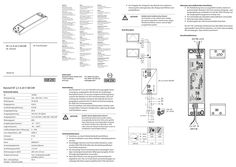
NT … A-24 V SM DIR
XX Vor Freigabe der Anlage für den Betrieb eine Isolationsmessung des Leitungsnetzes der Anlage durchführen und protokollieren. GEFAHR! Gefahr durch elektrischen Strom! Vor Arbeiten an der elektrischen Anlage die Spannungszufuhr unterbrechen, gegen Wiedereinschalten sichern und auf Spannungsfreiheit prüfen. Anschlussplan Hinweise zum elektrischen Anschluss: XX Die Verkabelung muss so ausgeführt werden, damit ein ausreichender Abstand (>20 mm) zwischen Eingangs- und Ausgangsleitung vorhanden ist und die 230V-Leitung und die Ausgangsleitung getrennt verlegt sind XX Für Litzenkabel grundsätzlich Aderendhülsen verwenden XX Nicht benutzte Adern isolieren XX Anschlussplan der 24V-Fensterantriebe beachten. Bei 24 V DC und langer Zuleitung muss das Kabel einen genügend großen Querschnitt aufweisen, um einen Spannungsabfall vorzubeugen. Querschnitt berechnen! Anschlussklemmen 24 V DC, 2,5 A ∓ ± DE Anschlussplan NT 2,5 A-24 V SM DIR DE Netzteil 195297-01 Netzteil NT 2,5 A-24 V SM DIR Technische Daten ID 195293 Netzspannung 220 - 240 V AC +/-10% Netzfrequenz 50-60 Hz Eingangsstrom 0,58 A Leerlaufeingangsleistung 0,24 W Ausgangsleistung 60 W Ausgangsspannung 24 V DC ±5% (SELV) Ausgangsstrom 2,5 A, ED 30%, … Min ON, … Min OFF Wirkungsgrad 89% Umgebungstemperatur -10 …+70° C Lagertemperatur -40 …+80°C Luftfeuchtigkeit (ohne Betauung) 0…95% max. Einbauhöhe ü. NN 2000 m Schutzart IP 20 Schutzklasse II Norm EN60335-1 Anwendungsbereich trockene Räume Anschlussquerschnitt 1,5 mm² Abmessungen (LxBxH) 200 x 50 x 25 mm Gruppensteuerung max. 10 Netzteile parallel schaltbar (230 V) Max. Leitungslänge Schalter ↔ Netzteil (230V) 50 m 230V AC NT 2,5 A-24 V SM DIR Anwendung Das Netzteil NT 2,5 A-24 V SM DIR ist eine geregelte Stromversorgung, ausgelegt für den Einsatz am einphasigen Wechselstromnetz. Es hat eine integrierte Richtungssteuerung für den Betrieb von 24 V-Fensterantrieben. Die Laufrichtung der Antriebe wird durch die Polarität der Versorgungsspannung bestimmt. Es dient als Stromversorgung für GEZE 24 V-Fensterantriebe. Der einwandfreie und sichere Betrieb dieses Gerätes setzt sachgemäßen Transport, fachgerechte Lagerung, Montage und Installation voraus. GEFAHR! LTA-LSA (ID: 118476) Gefahr durch elektrischen Strom! Beim Betrieb elektrischer Geräte stehen zwangsläufig bestimmte Teile unter gefährlicher Spannung. Unsachgemäßer Umgang mit diesen Geräten kann deshalb zu Tod oder schweren Körperverletzungen sowie zu erheblichen Sachschäden führen. Sicherheitshinweise XX Anschluss nur durch Elektrofachkraft durchführen. XX Vor der Installation muss dieses Beiblatt unbedingt gelesen werden. XX Einschlägige Normen und Vorschriften beachten, insbesondere DIN VDE 0100-600 oder die länderspezifischen Vorschriften beachten. XX Als netzseitige Trennvorrichtung einen bauseitigen 2-poligen Leistungsschutzschalter (Überspannungskat. III) mit Verrieglungsmöglichkeit verwenden. XX Nach dem Einbau muss der gesamte Klemmenbereich abgedeckt sein. Nur so ist das Gerät ausreichend gegen unzulässiges Berühren spannungsführender Teile geschützt. 230V AC L1i L2h N 230 V AC 24V A 24V B Signal LIN 230V AC GND +24V L1-N +24V GND L2-N DANGER! Danger of electric shock! Before working on the electrical system interrupt the power supply, secure it against being switched on again and verify the safe isolation from supply. Wiring diagram Notes on electrical connection: XX The cabling must be carried out in such a way that there is sufficient clearance (> 20 mm) between input and output line and the power line and output line are laid separately XX Always use wire-end ferrules for wire cores XX Insulate wires that are not used XX Wiring diagram of the 24V window drives has to be considered. At 24 V DC and with long supply cable, the cable must have a sufficiently large cross-section to prevent voltage drop. Calculate cross-section! Connection terminals 24 V DC, 2,5 A ∓ ± EN Wiring diagram NT 2,5 A-24 V SM DIR EN Power supply NT 2,5 A-24 V SM DIR 230V AC 195297-01 NT 2,5 A-24 V SM DIR power supply Technical data ID 195293 Mains voltage 220 - 240 V AC +/-10% Mains frequency 50-60 Hz Input current 0,58 A Idling input power 0,24 W Output power 60 W Output voltage 24 V DC ±5% (SELV) Output current 2,5 A, ED 30%, … Min ON, … Min OFF Efficiency 89% Ambient temperature -10 …+70° C Storage temperature -40 …+80°C Air humidity (without condensation) 0…95% max. installation height a.s.l. 2000 m IP rating IP 20 Protection rating II Standard EN60335-1 Application area dry rooms Connection cross-section 1,5 mm² Dimensions (LxWxH) 200 x 50 x 25 mm Group control max. 10 power supplies can be connected in parallel (230 V) Max. cable length switch ↔ power supply (230V) 50 m Application The NT 2,5 A-24 V SM DIR power supply is a controlled power supply designed for use in the one-phase AC network. It has an integrated direction control for the operation of 24 V window drives. The running direction of the drives is determined by the polarity of the supply voltage. It serves as a power supply for GEZE 24 V window drives. Perfect and safe device operation requires adequate transport, proper storage, assembly and installation. DANGER! LTA-LSA (ID: 118476) Danger of electric shock! During the operation of electrical devices, certain parts are always energised with hazardous voltage. Improper use of these devices can thus lead to death or serious physical injuries as well as to considerable property damage. Safety instructions XX Always have the connection set up by a qualified electrician. XX This supplementary sheet must always be read before installation. XX Heed the relevant standards and regulations, in particular DIN VDE 0100-600 or country-specific regulations. XX As a line-side disconnecting device, use an on site 2-pole circuit breaker (overvoltage cat. III) with locking possibility. XX The entire connector area must be covered after installation. This is the only way to protect the device sufficiently against impermissible contact with live parts. XX Before the system is released for operation, an insulation measurement of the system's line network must be performed and logged. 230V AC 24V A 24V B Signal LIN 230V AC GND +24V L1-N +24V GND L2-N L1i L2h N 230 V AC
PDF | 1 MB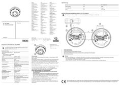
GC 162 RWA smoke detector
Signalisierung LED Stromaufnahme spannungslos aus … mA Normalbetrieb aus 70 μA Alarm ein 15-20 mA Anschluss Notstromsteuerzentrale MBZ300, THZ, THZ Comfort: Die maximale Anzahl der Rauch- bzw. Wärmemelder je Linie ist abhängig von der Zentrale. + - … DE Beiblatt … 1 … - DE Deckenrauchmelder + 24 V GC 162 RWA + … 184134-01 Deckenrauchmelder GC 162 RWA … 1 … Dazu Montageanleitungen MBZ 300, THZ und THZ Comfort beachten, siehe www.geze.com. Magnetsensor zum Testen (hinter GEZE Logo) LED zur Zustandsanzeige Technische Daten Deckenrauchmelder GC 162 RWA mit: à Rauchmelder GC 002 D RWA à Sockel GC 160 B RWA Farbe Abmessungen (mit Sockel, DxH) Gewicht Standard Funktionsprinzip Insektengitter Eingangsspannung Eingangsstrom Einbaulage Umgebungstemperatur Alarmwiderstand Signalübertragung Alarmrücksetzung Verwendung Meldertest Mat. Nr. 184110 … weiß, RAL 9010 110 mm x 54 mm 130 g EN 54-7: 2018 Streulicht, Alarmschwellennachführung speichernd verhindert das Eindringen von Insekten in die Messkammer 24 V DC (10-30 V DC) Ruhe: max. 60 µA Alarm: max. 20 mA Deckenmontage -30°C bis 70°C 1,2 kΩ 2-Leiter-Technik Stromerhöhung mit Selbsthaltung durch Taste in Zentrale nur mit GEZE Notstromsteuerzentrale Alarmauslösung - mit Testmagnet in der Nähe des Magnetsensors - mit Prüfgas Verwendung Der GC 162 RWA ist ein Deckenrauchmelder zur Verwendung in GEZE RWA-Anlagen. Rauchmelder erkennen Rauch. Sie arbeiten nach dem Streulichtprinzip. Ein Lichtsender und ein Lichtempfänger sind in der Messkammer so angeordnet, dass normalerweise kein Licht auf den Empfänger fällt. Befinden sich Schwebeteilchen (Rauch) in der Messkammer, so streuen diese einen Teil des Lichtes auf den Empfänger, der dieses in ein elektrisches Signal umsetzt. Ein Rauchmelder erkennt also nicht nur Rauch, sondern auch alle anderen Schwebeteilchen und reagiert empfindlich auf Verschmutzung. Diese Rauchmelder arbeiten nach dem Stromerhöhungsprinzip. Im Alarmfall ändert sich die Stromaufnahme des Melders. Schutz des Rauchmelders vor Verschmutzung à Die Staubschutzkappe des Rauchmelders erst bei der Inbetriebnahme entfernen. à Nach Einbau des Rauchmelders und Entfernung des Staubschutzes darauf achten, dass kein Staub in die Messkammer gelangt. Dies führt zu einer erhöhten Verschmutzung und kann die Lebensdauer des Rauchmelders erheblich verkürzen. à Die Messkammer eines Rauchmelders darf nicht geöffnet werden. Abschlusswiderstand zur Leitungsüberwachung Im Sockel GC 160 B des letzten Rauchmelders einer Linie muss ein 10 kΩ Abschlusswiderstand eingebaut werden. Der Widerstand liegt der Zentrale bei. … 2 … 4 … Erster Rauchmelder Letzter Rauchmelder Endwiderstand im letzten Melder einsetzen Klemmleiste GEZE Notstromsteuerzentrale (siehe zugehörigen Anschlussplan) Rauchmelderanschluss Testen Zum Testen, Prüfgas eines anerkannten Herstellers verwenden und entsprechend den Hersteller-Anweisungen anwenden. à Die rote LED am Melder muss innerhalb von 40 Sekunden in den Alarmzustand gehen. à An der Zentrale muss ein Alarm aktiviert werden. à Nach Abschluss des Tests, Alarm an der Zentrale zurücksetzten und Melderlinien-Reset durchführen. Hiermit erklärt die GEZE GmbH, dass diese Produkte den Richtlinien 2014/30/EU und 2011/65/EU entsprechen. Der vollständige Text der EU-Konformitätserklärung, sowie die Leistungserklärung, ist unter der folgenden Internetadresse verfügbar: www.geze.com. Signalling LEDs Current consumption Voltage-free off … mA Normal operation off 70 μA Alarm on 15-20 mA Connection of the emergency power supply control unit MBZ300, THZ, THZ Comfort: The maximum number of smoke or heat detectors per line depends on the control unit. + - … EN Supplement … 1 … - EN Ceiling-mounted smoke detector + 24 V GC 162 RWA + … 184134-01 Ceiling-mounted smoke detector GC 162 RWA … Refer to installation instructions MBZ 300, THZ and THZ Comfort, see www.geze.com. … 2 Magnetic sensor for testing (behind the GEZE logo) LED for displaying state Technical data Ceiling-mounted smoke detector GC 162 RWA with: à Smoke detector GC 002 D RWA à Base GC 160 B RWA Colour Dimensions (with base, DxH) Weight Standard Functional principle Mat. no. 184110 Insect grid prevents insects getting into the measuring chamber Input voltage Input current 24 V DC (10-30 V DC) Static: max. 60 µA Alarm: max. 20 mA Installation position Ambient temperature Alarm resistance Signal transmission Ceiling mounting -30°C to 70°C … kΩ 2-conductor technology current increase with self-locking Alarm reset Use by key in control unit only with GEZE emergency power supply control unit Detector test Alarm triggering - using test magnet near the magnetic sensor - using test gas … white, RAL 9010 110 mm x 54 mm 130 g EN 54-7: 2018 Scatter light, adaption of the alarm threshold, retentive Use The GC 162 RWA is a ceiling-mounted smoke detector for use in GEZE RWA systems. Smoke detectors detect smoke. They work using the light scatter principle. A light transmitter and a light receiver are arranged in the measuring chamber in such a way that no light reaches the receiver module in the normal case. If there are suspended particles (smoke) in the measuring chamber, these scatter part of the light onto the receiver module, which converts this into an electric signal. In other words, a smoke detector not only detects smoke but all other suspended particles and responds sensitively to soiling. These smoke detectors work according to the principle of current increase. In the event of an alarm, the current consumption of the detector changes. Protection of the smoke detector from soiling à Do not remove the dust protection cap from the smoke detector until commissioning is about to take place. à After the smoke detector has been installed and the dust protection removed, make sure no dust gets into the measuring chamber. This leads to increased soiling and can significantly shorten the service life of the smoke detector. à The measuring chamber of a smoke detector must not be opened. Terminating resistor for line monitoring There must be a 10 kΩ terminating resistor built into the base GC 160 B of the last smoke detector in a line. The resistor is included with the control unit. … 2 … 4 … First smoke detector Last smoke detector Insert the terminal resistor in the last detector Terminal strip GEZE emergency power supply control unit (see respective wiring diagram) Smoke detector connection Test Use test gas from a recognised manufacturer for testing in accordance with the manufacturer’s instructions. à The red LED on the detector must change to the alarm state within 40 seconds. à An alarm must be activated on the control unit. à After the test has been completed, reset the alarm on the control unit and carry out a detector line reset. GEZE GmbH hereby declares that this product comply with directives 2014/30/EU and 2011/65/EU. The complete text of the EU Declaration of Conformity, and the Declaration of Performance, is available at the following Internet address: www.geze.com.
PDF | 5 MB
Tandem power supply E 48
PDF | 224 KB

E 212, 24V
DWG | 38 KB
E 212 R1 /230 V AC, E 212 R /230 V AC, E 212 /24 V DC
E 212 R1 /230 V AC E 212 R /230 V AC E 212 /24 V DC DE Linearantrieb GB Linear drive DE Anschlussplan GB Wiring diagram E 212 R1 / E 212 R / E 212 Inhaltsverzeichnis … 2 Symbole und Darstellungsmittel … Sicherheitshinweise … Produkthaftung … Allgemeine Sicherheitshinweise … Montagehinweise … Leitungsverlegung und elektrischer Anschluss … Sicherheitsbewusstes Arbeiten und Benutzen … Prüfen der montierten Anlage … 3 … 5 … 7 Entsorgung der Fensteranlage … Wartung … Elektrischer Anschluss … Technische Daten … Hub-/Endlageeinstellung … 10 Anhang: Anschlussplan E 212 R1 /230 V … I Anschlussplan E 212 R /230 V … II Anschlussplan E 212 /24 V … III EG-Konformitäts- und Einbauerklärung … IV DE … Symbole und Darstellungsmittel E 212 R1 / E 212 R / E 212 … Symbole und Darstellungsmittel Warnhinweise In dieser Anleitung werden Warnhinweise verwendet, um Sie vor Sach- und Personenschäden zu warnen. XX Lesen und beachten Sie diese Warnhinweise immer. XX Befolgen Sie alle Maßnahmen, die mit dem Warnsymbol und Warnwort gekennzeichnet sind. Warnsymbol Warnwort GEFAHR! Bedeutung Gefahren für Personen. Nichtbeachtung führt zu Tod oder schweren Verletzungen. Weitere Symbole und Darstellungmittel Um die korrekte Bedienung zu verdeutlichen, sind wichtige Informationen und technische Hinweise besonders herausgestellt. Symbol Bedeutung bedeutet „Wichtiger Hinweis“ bedeutet „Zusätzliche Information“ XX … Symbol für eine Handlung: Hier müssen Sie etwas tun. XX Halten Sie bei mehreren Handlungsschritten die Reihenfolge ein. Sicherheitshinweise Für die Sicherheit von Personen ist es wichtig, diesen Sicherheitshinweisen Folge zu leisten. Diese Anweisungen sind aufzubewahren! Das Produkt ist nicht dafür bestimmt durch Personen, einschl. Kinder, mit eingeschränkten physischen, sensorischen oder geistigen Fähigkeiten oder mangels Erfahrung und/oder mangels Wissen benutzt zu werden, es sei denn, sie werden durch eine für ihre Sicherheit zuständige Person beaufsichtigt oder erhielten von ihr Anweisungen wie das Produkt zu benutzen ist. Kinder nicht mit fest montierten Regel- und/oder Steuereinrichtungen spielen lassen und Fernsteuerungen außerhalb der Reichweite von Kindern halten. Personen, einschl. Kinder, sind fernzuhalten, wenn ein Schalter mit Aus-Voreinstellung betätigt wird oder wenn sich ein Fenster schließt, das durch ein Rauch- und Wärmeabzugssystem geöffnet wurde. … Produkthaftung àà Gemäß der im Produkthaftungsgesetz definierten Haftung des Herstellers für seine Produkte sind die hier und in den zugehörigen MonDE … Sicherheitshinweise E 212 R1 / E 212 R / E 212 tageanleitungen des Produkts enthaltenen Informationen (Produktinformationen und bestimmungsgemäße Verwendung, Fehlgebrauch, Produktleistung, Produktwartung, Informations- und Instruktionspflichten) zu beachten. Die Nichtbeachtung entbindet den Hersteller von seiner Haftungspflicht. àà Nur Sachkundige, die von GEZE autorisiert sind, dürfen Montage, Funktionsprüfung und Wartung durchführen. Eigenmächtige Veränderungen an der Anlage schließen jede Haftung von GEZE für daraus resultierende Schäden aus. àà Bei Kombination mit Fremdgeräten übernimmt GEZE keine Gewährleistung. Auch für Reparatur- und Wartungsaufgaben nur GEZE-Originalteile verwenden. … Allgemeine Sicherheitshinweise Nach der Maschinenrichtlinie 2006/42/EG ist vor der Inbetriebnahme der Anlage die Risikobeurteilung durchzuführen und die Anlage gemäß Anhang III der EG-Maschinenrichtlinie mit der CE-Kennzeichnung zu versehen. XX Den neuesten Stand von Richtlinien, Normen und länderspezifischen Vorschriften beachten, insbesondere: àà BGV A1 „Unfallverhütungsvorschrift, Grundsätze der Prävention“. àà BGV A3 „Elektrische Anlagen und Betriebsmittel“. àà ASR A1.6 „Fenster, Oberlichter, lichtdurchlässige Wände“. àà VDE 0100, Teil 600 „Errichten von Niederspannungsanlagen Teil 6. Prüfungen“. àà DIN EN 60335-1 „Sicherheit elektrischer Geräte für den Hausgebrauch und ähnliche Zwecke - Teil 1: Allgemeine Anforderungen“. àà DIN EN 60335-2-103 „Sicherheit elektrischer Geräte für den Hausgebrauch und ähnliche Zwecke - Teil 2-103: Besondere Anforderungen für Antriebe für Tore, Türen und Fenster; àà MLAR „Muster-Leitungsanlagen-Richtlinie“. Wenn die Risikobeurteilung ergibt, dass die werkseitig vorgegebene Schließgeschwindigkeit von ca. … mm/s eine besondere Gefahr (z. B. für Kinder) darstellt, sind weitere Schutzmaßnahmen, z.B. Schalter mit AusVoreinstellung (Taster / Totmannbetrieb), zu treffen. Keine Schutzmaßnahmen sind notwendig, wenn die Einbauhöhe des Fensters ≥ 2,5 m über der Zugangsebene ist. … Montagehinweise WARNUNG DE … Wichtige Anweisungen für die sichere Montage. Alle Anweisungen beachten. Falsche Montage kann zu ernsthaften Verletzungen führen. Der Antrieb ist dazu bestimmt an Fenstern in einer Höhe von ≥ 2,5 m über der Zugangsebene montiert zu werden. E 212 R1 / E 212 R / E 212 Sicherheitshinweise Lesen und beachten Sie die Angaben in der Montageanleitung und bewahren Sie diese für den späteren Gebrauch auf. Alle Maßangaben sind am Bau eigenverantwortlich zu prüfen. àà Der Antrieb ist ausschließlich für den Einsatz in trockenen Räumen bestimmt und darf keiner stark korrosionsgefährdenden Umgebung ausgesetzt werden (z.B. Meeres- oder Seeluft). XX Um Verletzungen zu vermeiden, sind Schutzkappen auf überstehende Gewinde der Befestigungsschrauben zu setzen. XX Prüfen, ob die auf dem Typenschild des Antriebes angegebenen Bedingungen wie Umgebungstemperatur und elektrische Daten am vorgesehenen Einbauort eingehalten werden. XX Vor dem Einbau prüfen, ob das angetriebene Teil in einem guten mechanischen Zustand ist, gewichtsmäßig ausgeglichen ist und sich leicht schließen lässt. XX Sicherstellen, dass ein Einschließen zwischen dem Fenster und den umgebenden festen Teilen aufgrund der Öffnungsbewegung des Fensters verhindert wird. XX Bei Einbauhöhen unter 2,5m über Zugangsebene ist ein Schalter mit Aus-Voreinstellung (Taster) zu verwenden. XX Das Betätigungselement von Schaltern mit Aus-Voreinstellung muss in direkter Sichtweite vom Fenster, aber entfernt von sich bewegenden Teilen angebracht sein; falls es kein Schlüsselschalter ist, muss es in einer Höhe von mindestens 1,5 m und unzugänglich für die Öffentlichkeit angebracht sein. XX Bei Montage beachten: àà Bei Kippfenstern eine geeignete Fangsicherung verwenden (z.B. GEZE Sicherheitsschere Nr. 35) àà Zur Befestigung dürfen nur Original-Konsolen verwendet werden. àà Zur Montage geeignete Befestigungselemente benutzen. Empfehlungen finden sich in den Montageanleitungen. Sicherstellen, dass die Befestigungselemente im Profil für einen sicheren Halt der montierten Teile sorgen. … Leitungsverlegung und elektrischer Anschluss XX XX XX Vor Arbeiten an der elektrischen Anlage die Spannungszufuhr (Netz und Akku) unterbrechen und auf Spannungsfreiheit prüfen. Sicherstellen dass der Anschluss an die Netzspannung nur von einer Elektrofachkraft durchgeführt wird. Netzanschluss und Schutzleiterprüfung müssen entsprechend DIN VDE 0100-600 durchgeführt werden. Als netzseitige Trennvorrichtung einen bauseitigen, 2-poligen Sicherungsautomaten, entsprechend der zulässigen Strombelastbarkeit des Kabels, verwenden. DE … Sicherheitshinweise E 212 R1 / E 212 R / E 212 Bei den Anschlüssen von Komponenten müssen die Angaben in dieser Beschreibung beachtet werden. Die Planung und Berechnung des Leistungsnetzes obliegt dem sachkundigen Errichter und muss entsprechend der gesetzlichen Vorschriften durchgeführt werden (in Deutschland z. B. nach der MLAR). XX Vor der Freigabe der Anlage für den Betrieb eine lsolationsmessung des Leitungsnetzes der Anlage durchführen und protokollieren. XX Nur die im Anschlussplan angegebenen Kabel verwenden. Kabelart, Leitungslänge und -querschnitt gemäß den technischen Angaben ausführen. XX Für Litzenkabel grundsätzlich Aderendhülsen verwenden. XX Nicht benutzte Adern isolieren. Bei 24VDC und langer Zuleitung muss das Kabel einen genügend großen Querschnitt aufweisen, um einem Spannungsabfall vorzubeugen. Zur Querschnittberechnung siehe Kabelplan für RWA-Zentralen. … Sicherheitsbewusstes Arbeiten und Benutzen XX XX XX XX àà àà àà àà … Arbeitsplatz gegen unbefugtes Betreten sichern. Schwenkbereich langer Anlagenteile beachten. Vor Arbeiten an elektrischen Anlagen die Spannungszufuhr unterbrechen und die Spannungsfreiheit prüfen. Bei Verwendung einer unterbrechungsfreien Stromversorgung (USV) ist die Anlage auch bei netzseitiger Freischaltung unter Spannung. Antriebe beim Einrichten nur im Tastbetrieb ansteuern. Verletzungsgefahr bei geöffnetem Antrieb durch bewegte Teile (Einziehen von Haaren, Kleidungsstücken usw.) Verletzungsgefahr durch nicht gesicherte Quetsch-, Stoß-, Scher- und Einzugsstellen. Verletzungsgefahr durch Glasbruch. Anfassen der Fensteranlage während des Betriebs kann zu Verletzungen führen. Prüfen der montierten Anlage àà Maßnahmen zur Absicherung bzw. Vermeidung von Quetsch-, Stoß, Scher- und Einzugsstellen sind insbesondere bei Gefahrenstellen von unter 2,5 m zu prüfen und durchzuführen. Eine Maßnahme ist z.B. die Verwendung eines Schalters mit Aus-Voreinstellung (z.B. GEZE Lüftertaster LTA-LSA Mat.Nr. 118476). Bei Kindern oder Personen mit eingeschränktem Urteilsvermögen muss ein Schlüsselschalter mit Aus-Voreinstellung verwendet werden (z.B. GEZE Mat.Nr. 117996 für SCT, 090176 für Zylinder). Die Schalter müssen so angebracht sein, dass die Gefahrenstellen eingesehen werden können. DE … E 212 R1 / E 212 R / E 212 Entsorgung der Fensteranlage Nach der Installation ist zu überprüfen, dass die Anlage richtig eingestellt ist und richtig und gefahrlos funktioniert. XX Alle Funktionen durch Probelauf überprüfen. àà Der Endanwender muss nach der Fertigstellung in allen wichtigen Bedienschritten eingewiesen werden. XX … Entsorgung der Fensteranlage Die Fensteranlage besteht aus Materialen, die der Wiederverwertung zugeführt werden sollten. Dazu sind die Einzelkomponenten entsprechend ihrer Materialart zu sortieren. àà Aluminium (Profile) àà Eisen (Schrauben, Kette, ...) àà Kunststoff àà Elektronikteile (Motor, Steuerung, Transformator, Relais, ....) àà Kabel XX Die Teile entsprechend den gesetzlichen Bestimmungen entsorgen. … Wartung GEZE schreibt eine regelmäßige Wartung (mindestens 1x jährlich) vor. Diese ist von einem Sachkundigen auszuführen. Dabei müssen die Funktion sowie der Zustand der Mechanik (Ungleichgewicht oder Anzeichen von Verschleiß, Beschädigung von Befestigungsteilen) und der elektrischen Anschlüsse überprüft werden. Während der Reparatur- und Einstellarbeiten darf die Anlage nicht benutzt werden. XX Vor Beginn der Wartungsarbeiten die Spannungszufuhr (Netz und Akku) unterbrechen und auf Spannungsfreiheit prüfen. XX Befestigungen und Klemmschrauben auf festen Sitz prüfen. XX Bei Wartung den Antrieb von Verunreinigungen befreien. Achtung: Das Fenster schließt automatisch! Quetsch- und Klemmgefahr! Vor Montage beiliegende Sicherheitshinweise lesen und bei Montage und Betrieb des Antriebs beachten! Gewährleistungsansprüche setzen eine fachgerechte Montage, Installation und Wartung nach den Angaben des Herstellers voraus. XX XX Zur Information des Elektrikers diesen Anschlussplan aushändigen. Der Antrieb ist vor Bauschmutz und Strahlwasser zu schützen. DE … Elektrischer Anschluss … E 212 R1 / E 212 R / E 212 Elektrischer Anschluss GEFAHR! Gefahr durch elektrischen Strom! Beim Anschluss des Antriebs sicherstellen, dass keine Netzspannung an den Anschlussklemmen anliegt! E 212 R1 /230 V E 212 R /230 V E 212 /24 V Kabelführungsöffnung ausbrechen. Bei Leitungsdurchmesser >11 mm muss die Seitenkappe entsprechend größer ausgesägt werden. Nach dem Anschluss Seitenkappe wieder aufstecken und festschrauben. 230V N 230V PE Einfahren Ausfahren E 212 /24 V Einfahren, Impuls Ausfahren, Impuls L1 Dauerphase 230 V Leitungsüberwachung durch anschließen von Ader „3“ am letzten Motor der Gruppe. Für eine Bedienstelle, Dauersignale 230 V DE … 230V N 230V 230V PE … 2 … Für mehrere Bedienstellen mit integrierter Selbsthaltung, Impulssignale 230 V 24V 24V … 2 + Einfahren 1+2 Ausfahren Versorgung 24 V DC Versorgung 24 V DC Leitungsüberwachung Wechsel der Polarität der Versorgungsspannung, RWA-Zentralen E 212 R1 / E 212 R / E 212 … Technische Daten Technische Daten Hauptmaße Mechanische Daten E 212 /24 V DC max. Zug- und Druckkraft [N] E212 R1 230 V / E 212 R 230 V AC 1500 Hubgeschwindigkeit [mm/s] 1,5 1,5 Endlagenabschaltung Endschalter Endschalter Gewicht [kg] 1,2 1,2 max. Hublänge [mm] 70 mm, einstellbar 70 mm, einstellbar Einstellbereich Hub [mm] 42-70 42-70 Spannung 230 V AC +/- 10% 24 V DC +/- 25% Frequenz [Hz] 50 --- Einschaltdauer [%], S3 25 25 Kurzzeitbetrieb [min] … 3 Leistungsaufnahme [W] 50 29 Stromaufnahme [A] , ca. 0,2 1,2 Umgebungstemperatur [°C] -20/+60 -20/+60 Schutzart [IP] / Schutzklasse IP 42 / I IP 42 / III Anschlussart Festanschluss Festanschluss Anschlussquerschnitt max. [mm2] 1,5 Zuleitung E 212 R1: … x 1,5 mm E 212 R: … x 1,5 mm2 mit PE … x 1,5 mm2 ohne PE Anwendungsbereich trockene Räume trockene Räume 1500 Elektrische Daten 2,5 … Technische Änderungen vorbehalten! Die Endlagenabschaltung über Endschalter muss korrekt eingestellt werden. DE … Hub-/Endlageeinstellung … E 212 R1 / E 212 R / E 212 Hub-/Endlageeinstellung - … 2 + LED (grün) Einstellschraube Hub Der Hub ist ab Werk auf 52 mm eingestellt. XX Hub entsprechend Beschlaghub einstellen und prüfen. Einstellwert = Beschlaghub -2 mm. Beispiel OL90: Beschlaghub 54 mm = Einstellwert Antrieb 52 mm. Bei der Einstellung des Endschalters ist es wichtig, dass er richtig abschaltet und die grüne LED im Antrieb erlischt. Die Einstellung ist durch Probelauf zu überprüfen und sicherzustellen. DE 10 E 212 R1 / E 212 R / E 212 DE 11 E 212 R1 / E 212 R / E 212 Contents … 2 Symbols and means of representation … Safety instructions … 3 … 5 … 7 Disposal of the window unit … Maintenance … Electrical connection … Technical data … Product liability … General safety precautions … Installation notes … Routing cables and electrical connection … Safety-conscious working and usage … Inspection of installed system … Stroke/end position setting … 10 Appendix: Wiring diagram E 212 R1 /230 V … I Wiring diagram E 212 R /230 V … II Wiring diagram E 212 /24 V … III EC-declaration of conformity and incorporation … IV GB … E 212 R1 / E 212 R / E 212 … Symbols and means of representation Symbols and means of representation Warnings In these instructions, warnings are used to warn against material damage and injuries. XX Always read and observe these warnings. XX Observe all the measures that are marked with the warning symbol and warning word . Warning symbol Warning word Meaning Danger for individuals. DANGER! Failure to comply will result in death or serious injuries. Other symbols and means of representation Important information and technical notes are especially highlighted to explain correct operation. Symbol Meaning means "important note" means "additional information" XX … Symbol for an action: Here you have to do something. XX If there are several actions to be taken, keep to the given order. Safety instructions To ensure personal safety, it is important to follow these safety instructions. These instructions are to be retained! The product has not been designed to be used by people, including children, who have restricted physical, sensory or mental abilities or a lack of experience and/or knowledge, unless they are supervised by a person responsible for their safety or have received instructions from that person as to how the product is to be used. Do not allow children to play with permanently installed control systems of any kind and keep remote controls out of reach of children. People, including children, must be kept out of the way when a switch with OFF default setting is actuated or when a window that has been opened by a smoke and heat extraction system closes. … Product liability àà In accordance with the liability of the manufacturer for his products as defined in the German "Produkthaftungsgesetz" (Product Liability Act), GB … Safety instructions E 212 R1 / E 212 R / E 212 the information contained in this brochure and in the corresponding mounting instructions of the product (product information and proper use, misuse, product performance, product maintenance, obligations to provide information and instructions) is to be observed. Failure to comply releases the manufacturer from their statutory liability. àà Only qualified personnel who are authorised by GEZE may carry out mounting, function check and maintenance. GEZE shall not be liable for injuries or damage resulting from unauthorised modification of the equipment. àà GEZE shall not be liable if devices from other manufacturers are used with GEZE equipment. Use only original GEZE parts for repair and maintenance work as well. … General safety precautions In accordance with Machine Directive 2006/42/EC, a risk assessment must be performed and the system identified with the CE marking in accordance with Appendix III of the EC Machine Directive before commissioning the system. XX Observe the latest versions of guidelines, standards and country-specific regulations, in particular: àà BGV A1 "Accident-prevention regulations, General regulations" àà BGV A3 "Electrical systems and equipment" àà ASR A1.6 "Windows, skylights, translucent walls“. àà VDE 0100, Part 600 "Erection of low-voltage systems Part … Tests". àà DIN EN 60335-1 "Safety of electrical devices for home use and similar purposes - Part 1: General requirements" àà DIN EN 60335-2-103 "Safety of electrical devices for home use and similar purposes - Part 2-103: Special requirements for drives for gates, doors and windows" àà MLAR "Model Guideline for Line Systems" If the risk assessment shows that the closing speed of approx. … mm/s prescribed by the factor represents a special danger (e.g. for children), further protective measures, e.g. switch with OFF default setting (pushbutton / dead-man operation) must be taken. No protective measures are necessary if the installation height of the window is ≥ … m above the access level. … Installation notes WARNING GB … Important instructions for safe installation. Observe all the instructions. Incorrect installation can result in serious injuries. The drive has been designed for installation on windows at a height of ≥ … m above the access level. E 212 R1 / E 212 R / E 212 Safety instructions Read and observe the specifications in the mounting instructions and keep these for later use. All the dimensions specified have to be checked on site on own initiative and responsibility. àà The drive is designed solely for use in dry rooms and may not be subjected to highly corrosive environments (e.g. sea air or marine air). XX In order to avoid injuries protective caps are to be placed onto projecting threads of the fastening screws. XX Check whether the conditions specified on the information plate of the drive such as the ambient temperature and electrical data are observed at the planned installation site. XX Before mounting the driven part check whether it is in a good mechanical state, has a balanced weight and can be closed easily. XX Ensure that nothing can become trapped between the window and the surrounding components due to the opening movement of the window. XX In the case of installation heights less than … m above the access level, a switch with OFF default setting (push-button) must be used. XX The actuation element of switches with OFF default setting must be attached in direct view of the window, but away from moving parts; if it is not a key-operated switch it must be attached at a height of at least … m and be inaccessible to the general public. XX During installation, heed the following: àà With bottom-hung windows, use a suitable collecting safety device (e.g. GEZE safety scissor no. 35). àà Only genuine consoles may be used for attachment. àà Use suitable fixing elements for installation. Recommendations can be found in the installation instructions. Make sure that the fixing elements in the profile guarantee safe fixing of the installed parts. … Routing cables and electrical connection Before working on the electrical system, interrupt the power supply (mains and battery) and verify the safe isolation from supply. XX Ensure that the connection to the power supply is only carried out by a qualified electrician. The power connection and safety earth conductor test must be carried out in accordance with DIN VDE 0100-600 XX Use a customer-accessible double pole overload cut-out as the line-side disconnecting device in accordance with the permissible current carrying capacity of the cable. The specifications in this description have to be observed when connecting components. Planning and calculation of the power network is to be done by a qualified installer and has to be carried out in accordance with the statutory regulations (in Germany for example in accordance with MLAR). XX GB … Safety instructions XX XX XX XX E 212 R1 / E 212 R / E 212 Before the system is approved for operation carry out and log an isolation measurement of the supply network of the system. Use only cables prescribed in the wiring diagram. Implement the cable type, line length and cross-section in accordance with the technical specifications. Always use wire-end ferrules for wire cores. Insulate the cores that are not used. In the case of 24 V DC and a longer power supply cable, the cable must have a sufficiently large cross-section in order to prevent a voltage drop. See cable plan for RWA central control units for cross-section calculation. … Safety-conscious working and usage XX XX XX XX àà àà àà àà … Secure workplace against unauthorised entry. Watch swivelling range of long system parts. Before working on the electrical system interrupt the power supply and verify the safe isolation from supply. When using an uninterrupted power supply (UPS), the system will still be under power even when disconnected from the mains. During the set-up actuate the drives only in inching mode. Risk of injury through moving parts when a drive is opened (drawing in of hair, clothing, etc.) Risk of injury by unsecured trapping, knocking, shearing and draw-in points Risk of injury due to glass breakage. Touching the window unit can result in injuries during operation. Inspection of installed system àà The measures for security and prevention of crushing, impact, shearing or drawing-in spots, in particular at points with a height of less than … m are to be considered and carried out. One measure, for example, is the use of switch with OFF default setting (e.g. GEZE vent switch LTA-LSA Mat. No. 118476). In the case of children or persons with a limited ability to judge, a key-operated switch with an OFF default setting must be used (e.g. GEZE Mat. No. 117996 for SCT, 090176 for cylinder). The switch has to be mounted so that the points of danger can be seen. XX After the installation has been completed, check that the system is set correctly and is functioning correctly and safely. XX Check all the functions by means of a trial run. àà The end user has to be instructed in all the important operating and handling steps after completion. GB … E 212 R1 / E 212 R / E 212 … Disposal of the window unit Disposal of the window unit The window unit consists of materials that have to be recycled. The individual components have to be sorted in accordance with their material type. àà Aluminium (profiles) àà Iron (screws, chain, ...) àà Plastic àà Electronic components (motor, controller, transformer, relay, ...) àà Cables XX Dispose of the parts in accordance with the statutory regulations. … Maintenance GEZE prescribes regular maintenance (at least once a year). This is to be carried out by a suitably qualified person. In the process the operation as well as the condition of the mechanical equipment (imbalance or signs of wear, damage to fastening parts) and the electrical connections are to be checked. The system may not be used during repair and setting work. XX Before starting maintenance work, interrupt the power supply (mains and battery) and verify the safe isolation from supply. XX Inspect the fixations and clamping screws for firm seating. XX Clean soiling from the drive during maintenance. Caution: The window closes automatically!! Danger of pinching and clamping! Before installation, read the enclosed safety notes and follow these during installation and operation of the drive! Warranty claims require proper mounting, installation and maintenance in accordance with the manufacturer's specifications. XX XX Inform the electrician by handing out this wiring diagram. The drive must be protected from construction dirt and splash water. GB … Electrical connection … E 212 R1 / E 212 R / E 212 Electrical connection DANGER! Danger of electric shock! When connecting the drive, make sure there is no mains voltage at the supply terminals! E 212 R1 /230 V E 212 R /230 V E 212 /24 V Break to the cable duct opening. With cable diameter > 11 mm, the side cap must be sawn out correspondingly larger. After connection, put the side cap back in place and screw tightly. 230V N 230V PE Retract Extend E 212 /24 V Line control by connecting wire "3" to the last motor of the group. For one operating point, permanent signal 230 V. GB … 230V N 230V 230V PE Retract, pulse Extend, pulse L1 Permanent phase 230 V … 2 … For several operating points with integrated self-locking module, pulse signals 230 V. 24V 24V … 2 + Retract … +2 Extend Supply 24 V DC Supply 24 V DC Line control Change the polarity of the supply voltage, RWA controls E 212 R1 / E 212 R / E 212 … Technical data Technical data Main dimensions Mechanical data E212 R1 230 V / E 212 R 230 V AC Max. tensile force and force of pressure [N] 1500 E 212 /24 V DC Stroke speed [mm/s] … End position cut-off Limit switch Limit switch Weight [kg] … Max. stroke length [mm] 70 mm, adjustable 70 mm, adjustable Setting range, stroke [mm] 42-70 42-70 Voltage 230 V AC +/- 10% 24 V DC +/- 25% Frequency [Hz] 50 --- Switch-on duration [%], S3 25 25 Short-term operation [min] … 3 Power consumption [W] 50 29 Current consumption [A], approx. … Ambient temperature [°C] -20/+60 -20/+60 Enclosure rating [IP] / protection type IP 42 / I IP 42 / III Type of connection Fixed connection Fixed connection Max. connection cross-section [mm] … Supply cable E 212 R1: … x … mm E 212 R: … x … mm² with PE … x … mm2 without PE Area of application dry rooms dry rooms 1500 Electrical data … Subject to technical modifications! The end position cut-off over the limit switch must be set properly. GB … Stroke/end position setting … E 212 R1 / E 212 R / E 212 Stroke/end position setting - + … LED (green) … Setting screw stroke The stroke is set to 52 mm in the factory. XX Set and check the stroke according to fitting stroke Setting value = Fitting stroke – … mm Example OL90: Setting stroke 54 mm = Setting value drive 52 mm When adjusting the limit switch make sure that it is switched off correctly and the green LED on the drive has gone out. The setting must be checked and safeguarded by means of a test run. GB 10 E 212 R1 … x 1,5 mm2 LTA-LSA (ID: 118476) … x 1,5 mm2 230 V AC N PE BK 230 V AC BU N N BN - 230 V AC PE PE GN/YE - A-I E 212 R … x 1,5 mm2 LTA-230 (ID: 118474) … x 1,5 mm2 … x 1,5 mm2 230 V AC N A-II BK 230 V AC - BU N N GY - 230 V AC L1 BN 230 V AC 230 V AC PE GN/YE PE PE E 212 … x 1,5 mm2 24 V DC … GND 24 V DC … - - … 24 V DC GND A-III Notizen/Notes E 212 R1 / E 212 R / E 212 E 212 R1 / E 212 R / E 212 Notizen/Notes Germany GEZE Sonderkonstruktionen GmbH Planken … 97944 Boxberg-Schweigern Tel. +49 (0) 7930-9294-0 Fax +49 (0) 7930-9294-10 E-Mail: sk.de@geze.com GEZE GmbH Niederlassung Süd-West Tel. +49 (0) 7152-203-594 E-Mail: leonberg.de@geze.com GEZE GmbH Niederlassung Süd-Ost Tel. +49 (0) 89-120 07 42-50 E-Mail: garching.de@geze.com GEZE GmbH Niederlassung Ost Tel. +49 (0) 30-47 89 90-0 E-Mail: berlin.de@geze.com GEZE GmbH Niederlassung Mitte/Luxemburg Tel. +49 (0) 6171-63610-0 E-Mail: frankfurt.de@geze.com GEZE GmbH Niederlassung West Tel. +49 (0) 201-83082-0 E-Mail: essen.de@geze.com GEZE GmbH Niederlassung Nord Tel. +49 (0) 40-2 19 07 16-13 E-Mail: hamburg.de@geze.com GEZE Service GmbH Tel. +49 (0) 18 02/92 33 92 E-Mail: service-info.de@geze.com Austria GEZE Austria E-Mail: austria.at@geze.com Iberia GEZE Iberia S.R.L. E-Mail: info@geze.es Scandinavia – Denmark GEZE Danmark E-Mail: danmark.se@geze.com www.geze.at www.geze.es www.geze.dk Baltic States GEZE GmbH Baltic States office E-Mail: office-latvia@geze.com www.geze.com India GEZE India Private Ltd. E-Mail: office-india@geze.com www.geze.in Singapore GEZE (Asia Pacific) Pte, Ltd. E-Mail: gezesea@geze.com.sg www.geze.com Benelux GEZE Benelux B.V. E-Mail: benelux.nl@geze.com www.geze.be www.geze.nl Italy GEZE Italia S.r.l E-Mail: italia.it@geze.com www.geze.it South Africa GEZE Distributors (Pty) Ltd. E-Mail: info@gezesa.co.za www.geze.co.za GEZE Engineering Roma S.r.l E-Mail: roma@geze.biz www.geze.it Switzerland GEZE Schweiz AG E-Mail: schweiz.ch@geze.com www.geze.ch Bulgaria GEZE Bulgaria - Trade E-Mail: office-bulgaria@geze.com www.geze.bg China GEZE Industries (Tianjin) Co., Ltd. E-Mail: Sales-info@geze.com.cn www.geze.com.cn GEZE Industries (Tianjin) Co., Ltd. Branch Office Shanghai E-Mail: chinasales@geze.com.cn www.geze.com.cn GEZE Industries (Tianjin) Co., Ltd. Branch Office Guangzhou E-Mail: chinasales@geze.com.cn www.geze.com.cn GEZE Industries (Tianjin) Co., Ltd. Branch Office Beijing E-Mail: chinasales@geze.com.cn www.geze.com.cn France GEZE France S.A.R.L. E-Mail: france.fr@geze.com www.geze.fr Hungary GEZE Hungary Kft. E-Mail: office-hungary@geze.com www.geze.hu GEZE GmbH P.O.Box 1363 Reinhold-Vöster-Straße 21–29 71229 Leonberg Germany Poland GEZE Polska Sp.z o.o. E-Mail: geze.pl@geze.com www.geze.pl Romania GEZE Romania S.R.L. E-Mail: office-romania@geze.com www.geze.ro Russia OOO GEZE RUS E-Mail: office-russia@geze.com www.geze.ru Scandinavia – Sweden GEZE Scandinavia AB E-Mail: sverige.se@geze.com www.geze.se Scandinavia – Norway GEZE Scandinavia AB avd. Norge E-Mail: norge.se@geze.com Turkey GEZE Kapı ve Pencere Sistemleri E-Mail: office-turkey@geze.com www.geze.com Ukraine GEZE Ukraine TOV E-Mail: office-ukraine@geze.com www.geze.ua United Arab Emirates/GCC GEZE Middle East E-Mail: geze@emirates.net.ae www.geze.ae United Kingdom GEZE UK Ltd. E-Mail: info.uk@geze.com www.geze.com www.geze.no Scandinavia – Finland Branch office of GEZE Scandinavia AB E-Mail: finland.se@geze.com www.geze.com Tel.: 0049 7152 203-0 Fax: 0049 7152 203-310 www.geze.com 151531-00
PDF | 2 MB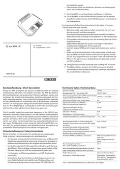
Supplementary sheet IQ box KNX UP
durchgeführt werden. àà Den neuesten Stand von Richtlinien, Normen und länderspezifischen Vorschriften beachten. XX XX Die IQ box KNX ist vor Bauschmutz und Wasser zu schützen. Die IQ box KNX ist ein Produkt des KNX-Systems und es werden detaillierte Fachkenntnisse durch KNX-Schulungen zum Verständnis vorausgesetzt. It is important to follow these instructions for the safety of persons. These instructions must be kept! àà Before assembly read enclosed safety instruction and carry out during assembly and drive operation! Warranty claims presuppose professional assembly, installation and maintenance according to the guidelines of the manufacturer. IQ box KNX UP àà Only qualified personnel may carry out mounting, function check and maintenance. GEZE shall not be liable for injuries or damage resulting from unauthorised modification of the equipment àà Use only original GEZE parts for repair and maintenance work as well. àà Make sure that the connection to the mains supply is made only by a qualified electrician. Power connection and ground conductor test must be performed in accordance with DIN VDE 0100-610. àà Observe the latest versions of guidelines, standards and countryspecific regulations. DE Beiblatt EN Supplementary sheet XX XX 164448-01 Kurzbeschreibung / Short description The IQ box KNX must be protected from building dirt and water. The IQ box KNX is a product of the KNX systems and detailed specialist know-how gained through KNX training is required for the product to be understood. Technische Daten / Technical data Die IQ box KNX ermöglicht das Steuern und Überwachen der GEZE IQ windowdrives (Slimchain, Powerchain etc.) über das KNX-Bus-System. Die Antriebe können auf gewünschte Positionen gefahren werden und es können die aktuelle Antriebsposition und diverse Zustände des Antriebs abgefragt werden. Zwei zusätzliche Eingänge können entweder für den Direktbetrieb (z.B. Handtaster) oder als Bus-Eingänge verwendet werden. Die Konfiguration erfolgt mit der KNX-Software ETS (ab Version … ). Die Produktdatenbank und detaillierte technische Beschreibungen sind zum Download auf der Internet-Seite www.geze.com. Ident-Nr. / ID-No. 164443 Busspannung KNX / Bus voltage KNX 30 V DC SELV *) The IQ box KNX makes the control and monitoring of the GEZE IQ windowdrives (Slimchain, Powerchain etc.) via the KNX-bus system possible. The drives can be moved to the required positions and the current drive position and various drive states can be requested. Two additional inputs can be used either for direct operation (e.g. manual push buttons) or as bus inputs. Configuration is done using the KNX software ETS (from version … ). The product database and detailed technical descriptions are available for downloading from the website www.geze.com. Sicherheitshinweise / Safety instructions Für die Sicherheit von Personen ist es wichtig, diesen Anweisungen Folge zu leisten. Diese Anweisungen sind aufzubewahren! àà Vor Montage beiliegende Sicherheitshinweise lesen und beachten! Gewährleistungsansprüche setzen eine fachgerechte Montage, Installation und Wartung nach den Angaben des Herstellers voraus. àà Nur Sachkundige dürfen Montage, Inbetriebnahme und Wartung durchführen. Eigenmächtige veränderungen an der Anlage schließen jede Haftung von GEZE für resultierende Schäden aus. àà Für Reparatur- und Wartungsaufgaben nur GEZE-Originalteile verwenden. àà Sicherstellen dass der Anschluss an die Netzspannung nur von einer Elektrofachkraft durchgeführt wird. Netzanschluss und Schutzleiterprüfung müssen entsprechend DIN VDE 0100-610 Versorgungsspannung IQ box KNX und Antriebe / 24 V DC, +-25%, SELV *) Supply voltage IQ box KNX and drives Max. Strom Antriebe / max. current drives 6A Eigenstromaufnahme an KNX-Bus Induced current intake to KNX-bus … mA Eigenstromaufnahme an 24V / Induced current intake to 24V 20 mA Schutzart / IP rating IP20 Schutzklasse / Protection rating III Umgebungstemperatur / Ambient temperature -5°C…+70°C Anschlussquerschnitt 24 V-Versorgung und Antriebe / Connection cross-section 24V supply and drives Anschlussquerschnitt Eingänge/Taster, starr oder flexibel ohne Aderendhülse / Connection cross-section push buttons, rigid or flexible without wire-end ferrule Anschluss KNX-Bus / KNX-bus connection max. 1,5 mm² Max. Leitungslänge Taster / Max. cable length for push button max. 0,5 mm² KNX-Anschlussklemme rot/ schwarz / KNX supply terminal red/ black 30 m Max. Gesamtleitungslänge Antriebe (LIN-BUS) / Max. overall cable length for drives (LIN-BUS) 50 m Maße / Dimensions 50 mm x 45 mm x 19 mm Montageort / Mounting location Gerätedose, Abzweigdose (DIN 49073 ) / Standard box, branch box (DIN 49073 ) *) SELV = Sicherheitskleinspannung / Safety extra-low voltage Elektrischer Anschluss / Electrical connection Anschlussplan IQ windowdrives ID 148327 beachten ! Nur verwendbar mit GEZE IQ windowdrives ab Software … . Heed the wiring diagram for IQ windowdrives ID 148327. Can only be used with GEZE IQ windowdrives from software version … onwards. *) Bei 24 V DC und langer Zuleitung muss das Kabel einen genügend großen Querschnitt aufweisen, um einen Spannungsabfall vorzubeugen. Querschnitt berechnen! … In the case of 24 V DC and a longer power supply line, the cable must have a sufficiently large cross-section in order to prevent a voltage drop. Calculate the cross-section. … max. … A + 230V AC … A B - + 24 V DC Die Gesamtkabellänge zwischen IQ box KNX und Fenster darf max. 50 m betragen. Bei Syncro- oder Verriegelungsantrieben zählen alle einzelnen Antriebsleitungen. Fenster / window S LIN - A B S L … A B S L … The overall cable length between IQ box KNX and window must not exceed max. 50 m. With Synchro or locking drives, all the individual drive cables count. GND +24V A B S L *) … IQ box KNX -+ COM 32 33 … 8 … 10 Taste Fenster ZU / Window OPEN key Taste Fenster AUF / Window CLOSED key Status LED (grün) / Status LED (green) … 5 … KNX Optional weitere Slaveantriebe (bei Syncro) oder Verriegelungsantriebe / Optional further Slave drives (with Syncro) or locking drives / Zusätzliche Abzweigdose für Anschluss mehrerer Antriebe / Additional branch box for the connection of several drives Netzteil 24V DC / 24V DC power supply IQ windowdrive Eingang S33 (Fenster ZU); parametrierbar / Input S33 (window CLOSED); parameters can be set Eingang S32 (Fenster AUF); parametrierbar / Input S32 (window OPEN); parameters can be set z. B. Lüftertaster LTA-24-AZ / e.g. Vent switch LTA-24-AZ … 4 … KNX + -- … 7 + -KNX Bedienelemente / Operating elements … 9 10 Dauerlicht / Continuous light: Blinken langsam / Slow flashing : Blinken schnell / Fast flashing: 11 12 11 12 Funktion ok / Function OK keine Kommunikation zum Antrieb / No communication to the drive Versorgungsspannung verpolt / Polarity of supply voltage reversed KNX Programmier-LED (rot) für Inbetriebnahme KNX-BUS / KNX programming LED (red) for commissioning KNX-BUS KNX Programmiertaste für Inbetriebnahme KNX-BUS / KNX programming key for commissioning KNX-BUS Zubehör / Accessories Material / Material Ident-Nr. / ID-No. Antriebe / Drives GEZE IQ windowdrives: ab SW … Slimchain, Powerchain, E 250 NT, E 90x, Power lock Lüftertaster / Vent switch LTA-24-AZ LTA-LSA ID 129393 ID 118476 Netzteile / Power supplies NT 1,1A-24 V UP NT 1,5A-24 V HS NT 2,5A-24 V HS NT 4,2A-24 V HS ID 151426 ID 151425 ID 151424 ID 151423 Testbetrieb / Test operation Nach Anschluss der Antriebe und der 24V-Versorgungsspannung kann mit Hilfe der Taste “Fenster AUF” (9) und der Taste „Fenster ZU“ (8) ein Probelauf der Antriebe durchgeführt werden, auch wenn das KNX-System noch nicht programmiert ist. Following connection of the drives and the 24V supply voltage, the key “Window OPEN” (9) and the key “Window CLOSED” (8) can be use to carry out a test run, even if the KNX system has not been programmed at this point. GEZE GmbH Reinhold-Vöster-Strasse 21–29 71229 Leonberg Germany Tel.: 0049 7152 203-0 Fax: 0049 7152 203-310 www.geze.com
PDF | 585 KB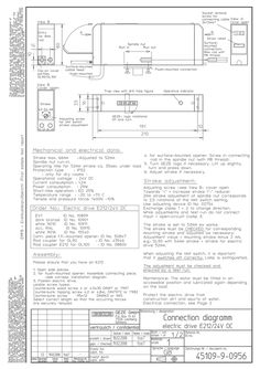
E-drive E 212 24V
PDF | 285 KB
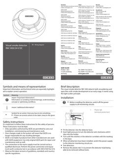
RM 1003 / 24 V DC optical smoke detector
Germany China GEZE Sonderkonstruktionen GmbH GEZE Industries (Tianjin) Co., Ltd. E-Mail: sk.de@geze.com E-Mail: Sales-info@geze.com.cn Russian OOO GEZE RUS E-Mail: office-russia@geze.com GEZE GmbH Niederlassung Nord-Ost E-Mail: berlin.de@geze.com GEZE Industries (Tianjin) Co., Ltd. Branch Office Shanghai E-Mail: chinasales@geze.com.cn GEZE GmbH Niederlassung West E-Mail: essen.de@geze.com GEZE Industries (Tianjin) Co., Ltd. Branch Office Guangzhou E-Mail: chinasales@geze.com.cn Scandinavia GEZE Scandinavia AB GEZE Sweden E-Mail: sverige.se@geze.com GEZE GmbH Niederlassung Mitte E-Mail: frankfurt.de@geze.com GEZE GmbH Niederlassung Süd-West E-Mail: leonberg.de@geze.com GEZE GmbH Niederlassung Süd-Ost GEZE Service GmbH NL Süd-West GEZE Service GmbH NL Nord-Ost GEZE Service GmbH NL West GEZE Service GmbH NL Mitte GEZE Service GmbH NL Süd Visual smoke detector RM 1003/24 V DC EN Wiring diagram Austria GEZE Austria GmbH E-Mail: austria.at@geze.com Baltic States GEZE GmbH Baltic States office E-Mail: office-latvia@geze.com Symbols and means of representation Important information and technical notes are especially highlighted to explain correct operation. Symbol Meaning means "Important Information"; Information on avoiding material damage, understanding a concept or optimising workflows. GEZE Scandinavia AB avd. Norge E-Mail: norge.se@geze.com GEZE Industries (Tianjin) Co., Ltd. Branch Office Beijing E-Mail: chinasales@geze.com.cn GEZE Finland E-Mail: finland.se@geze.com GEZE Denmark E-Mail: danmark.se@geze.com France GEZE France S.A.R.L. E-Mail: france.fr@geze.com Hungary GEZE Hungary Kft. E-Mail: office-hungary@geze.com Iberia GEZE Iberia S.R.L. E-Mail: info@geze.es Singapore GEZE (Asia Pacific) Pte. Ltd. E-Mail: gezesea@geze.com.sg South Africa DCLSA Distributors (Pty.) Ltd. E-Mail: info@gezesa.co.za Switzerland GEZE Schweiz AG E-Mail: schweiz.ch@geze.com India GEZE India Private Ltd. E-Mail: office-india@geze.com Turkey GEZE GmbH Türkiye - İstanbul E-Mail: office-turkey@geze.com Italy GEZE Italia S.r.l E-Mail: italia.it@geze.com Ukraine Repräsentanz GEZE Ukraine TOV E-Mail: office-ukraine@geze.com GEZE Engineering Roma S.r.l E-Mail: roma@geze.biz United Arab Emirates/GCC GEZE Middle East E-Mail: geze@emirates.net.ae Benelux GEZE Benelux B.V. E-Mail: benelux.nl@geze.com Poland GEZE Polska Sp.z o.o. E-Mail: geze.pl@geze.com Bulgaria GEZE Bulgaria - Trade E-Mail: office-bulgaria@geze.com Romania GEZE Romania S.R.L. E-Mail: office-romania@geze.com GEZE GmbH P.O.Box 1363 71229 Leonberg Germany Tel.: 0049 7152 203-0 Fax: 0049 7152 203-310 www.geze.com United Kingdom GEZE UK Ltd. E-Mail: info.uk@geze.com 153159-02 Brief description The visual smoke detector RM 1003 detects both smouldering and open fires with smoke development at an early stage. It works using the light scatter principle. Installation XX Before installing the detector, switch off the power supply to all monitoring circuits. means "additional information" … XX Symbol for an action: Here you have to do something. XX If there are several actions to be taken, keep to the given order. … Plastic tab (removal protection) Safety instructions It is important to follow these instructions for the safety of persons. These instructions must be kept. àà Only specialists authorised by GEZE are permitted to carry out installation, commissioning and maintenance work. àà Own changes made to the system will mean that GEZE is no longer responsible for any resulting damages. àà GEZE is not liable if products from other manufacturers are used with GEZE equipment. Use only original GEZE parts for repair and maintenance work as well. àà The connection to the mains supply must be carried out by a qualified electrician. Perform the power connection and equipment earth conductor test in accordance with VDE 0100 Part 610. àà Observe the latest versions of guidelines, standards and countryspecific regulations. XX XX XX XX XX XX Fit the detector into the detector base. Exert light pressure to turn the detector anti-clockwise until it slips into the holder. Turn until the notches in the detector correlate with the marking in the base. When all detectors have been installed, switch the power supply to the detector monitoring circuits on. Test detectors. Remove the plastic tab (1) to prevent the detector head being able to be removed without tools. Technical data Hold the test smoke under the detector. àà The red LED on the detector must change to a locked alarm state within 40 seconds. àà An alarm must be activated on the RWA control unit. XX Connection XX XX Remove the dust caps before commissioning the system. Heed wiring plan for the control unit. A maximum of 10 units or 20 units can be installed in series. (Depending on the control unit) … 2 Ø102 … Use a product from a recognised manufacturer to produce test smoke in accordance with the manufacturer's instructions. 42* Test * with base àà àà àà àà àà àà Functional principle Monitoring area Installation height Sensitivity Operating voltage Current consumption at 24 V DC àà idle àà during alarm àà Signal transmission àà Alarm reset àà Use … 4 + … 2 … 4 … 5 – First smoke detector Last smoke detector Insert the termination resistor in the last detector Terminal block GEZE emergency power control unit (see respective wiring diagram) Smoke detector connection àà Single indicator àà VdS approval àà Operating ambient temperature àà Dimensions with base àà Weight with base àà Colour visual light scatter principle according to application directives according to application directives DIN EN 54, Part … 8 V … 30 V DC max. 65 µA max. 20 mA 2-conductor technology current increase with self-locking by key in control unit only with GEZE emergency power control unit red LED G201060 -20 °C … +60 °C Ø 102 x 42 mm 120 g white, acc. to RAL 9016
PDF | 371 KB